1973 DATSUN B110 manual transmission
[x] Cancel search: manual transmissionPage 413 of 513
ENGINE
Choke
unloader
clearance
carburetor
body
C
between
choke
valve
and
mm
in
Bi
metal
resistance
ohms
2
01
0
07911
8
6t09
0
Accelerator
pump
Injector
hole
Return
spring
Fuel
pressure
mm
in
g
mm
Ib
in
kg
cm
2
psi
kg
lb
0
5
0
0197
78
I
I
0
18
2
6
Manual
transmission
Automatic
transmission
Weight
2
8
6
2
2
9
6
39
Example
1
215
represents
215
100
2
15
mm
0
0846
in
diameter
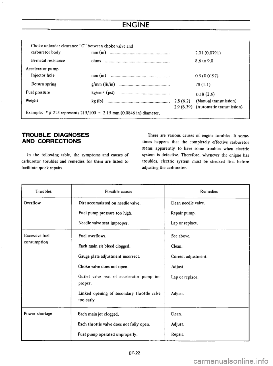
TROUBLE
DIAGNOSES
AND
CORRECTIONS
There
are
various
causes
of
engine
tarubles
It
some
times
happens
that
the
completely
effective
carburetor
seems
apparently
to
have
some
troubles
when
electric
system
is
defective
Therefore
whenever
the
enigne
has
troubles
electric
system
must
be
checked
first
before
adjusting
the
carburetor
In
the
following
table
the
symptoms
and
causes
of
carburetor
tarubles
and
remedies
for
them
are
listed
to
facilitate
quick
repairs
Troubles
Possible
causes
Remedies
Overflow
Dirt
accumulated
on
needle
valve
Clean
needle
valve
Fuel
pump
pressure
too
high
Repair
pump
Needle
valve
seat
improper
Lap
or
replace
Excessive
fuel
consumption
Fuel
overflows
See
above
Each
main
air
bleed
clogged
Clean
Gauge
plate
adjustment
incorrect
Correct
adjustment
Choke
valve
does
not
open
Adjust
Outlet
valve
seat
of
accelerator
pump
im
proper
Lap
or
replace
Linked
opening
of
secondary
throttle
valve
too
early
Adjust
Power
shortage
Each
main
jet
clogged
Clean
Each
throttle
valve
does
not
fully
open
Adjust
Fuel
pump
operated
improperly
Repair
EF
22
Page 431 of 513
ENGINE
ElECTRICAL
SYSTEM
SPECIFICATIONS
AND
SERVICE
DATA
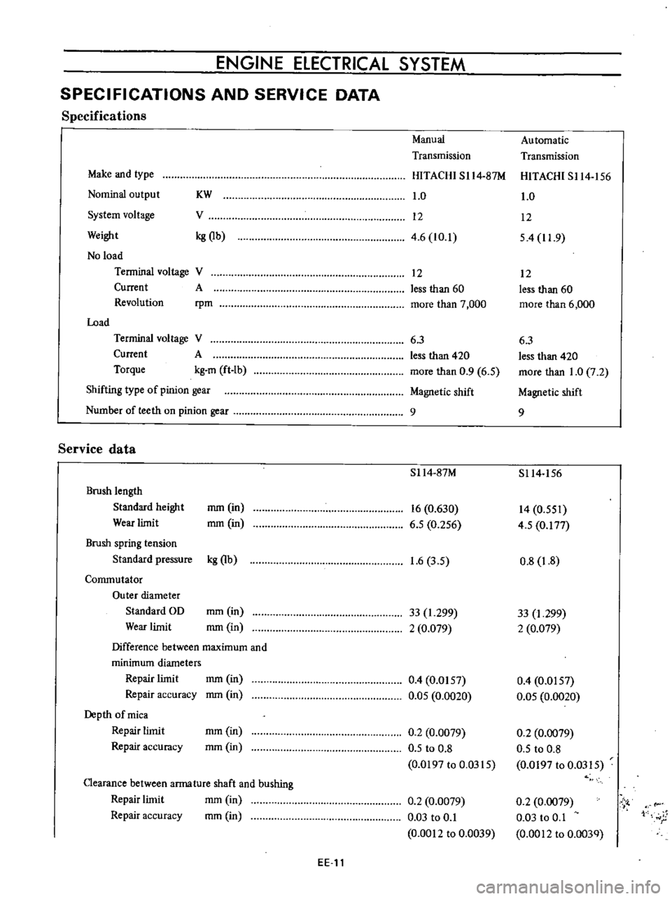
Specifications
Manual
Automatic
Transmission
Transmission
Make
and
type
HITACHI
SI14
87M
HITACHI
S114
156
Nominal
output
KW
1
0
1
0
System
voltage
V
12
12
Weight
kg
Qb
4
6
10
1
54
11
9
No
load
Terminal
voltage
V
12
12
Current
A
less
than
60
less
than
60
Revolution
rpm
more
than
7
000
more
than
6
000
Load
Terminal
voltage
V
6
3
6
3
Current
A
less
than
420
less
than
420
Torque
kg
m
ft
Ib
more
than
0
9
6
5
more
than
1
0
7
2
Shifting
type
of
pinion
gear
Magnetic
shift
Magnetic
shift
Number
of
teeth
on
pinion
gear
9
9
Service
data
S114
87M
S114
156
Brush
length
Standard
height
mm
in
16
0
630
14
0
551
Wear
limit
mm
in
6
5
0
256
4
5
0
177
Brush
spring
tension
Standard
pressure
kg
Qb
1
6
3
5
0
8
1
8
Commutator
Outer
diameter
Standard
OD
mm
in
33
1
299
33
I
299
Wear
limit
mm
in
2
0
079
2
0
079
Difference
between
maximum
and
minimum
diameters
Repair
limit
mm
in
0
4
0
0157
0
4
0
0157
Repair
accuracy
mm
in
0
05
0
0020
0
05
0
0020
Depth
of
mica
Repair
limit
mm
in
0
2
0
0079
0
2
0
0079
Repair
accuracy
mm
in
0
5
to
0
8
0
5
to
0
8
0
0197
to
0
0315
0
0197
to
0
0315
Clearance
between
arma
ture
shaft
and
bushing
mm
in
Repair
limit
0
2
0
0079
0
2
0
0079
Vi
Repair
accuracy
mm
in
0
03
to
0
1
0
03
to
0
1
1
r
0
0012
to
0
0039
0
0012
to
0
003Q
EE
11
Page 452 of 513
ENGINE
When
nothing
is
wrong
with
its
characteristics
con
ceivable
causes
are
defectiveness
or
abnormal
wearing
of
driving
part
or
others
Do
not
disassemble
it
When
characteristics
are
improper
check
earn
as
sembly
governor
weight
shaft
and
governor
spring
and
other
relative
parts
carefully
When
reassembling
the
centrifugal
advance
mechanical
part
be
sure
to
check
advance
characteristics
by
the
use
of
a
distributor
tester
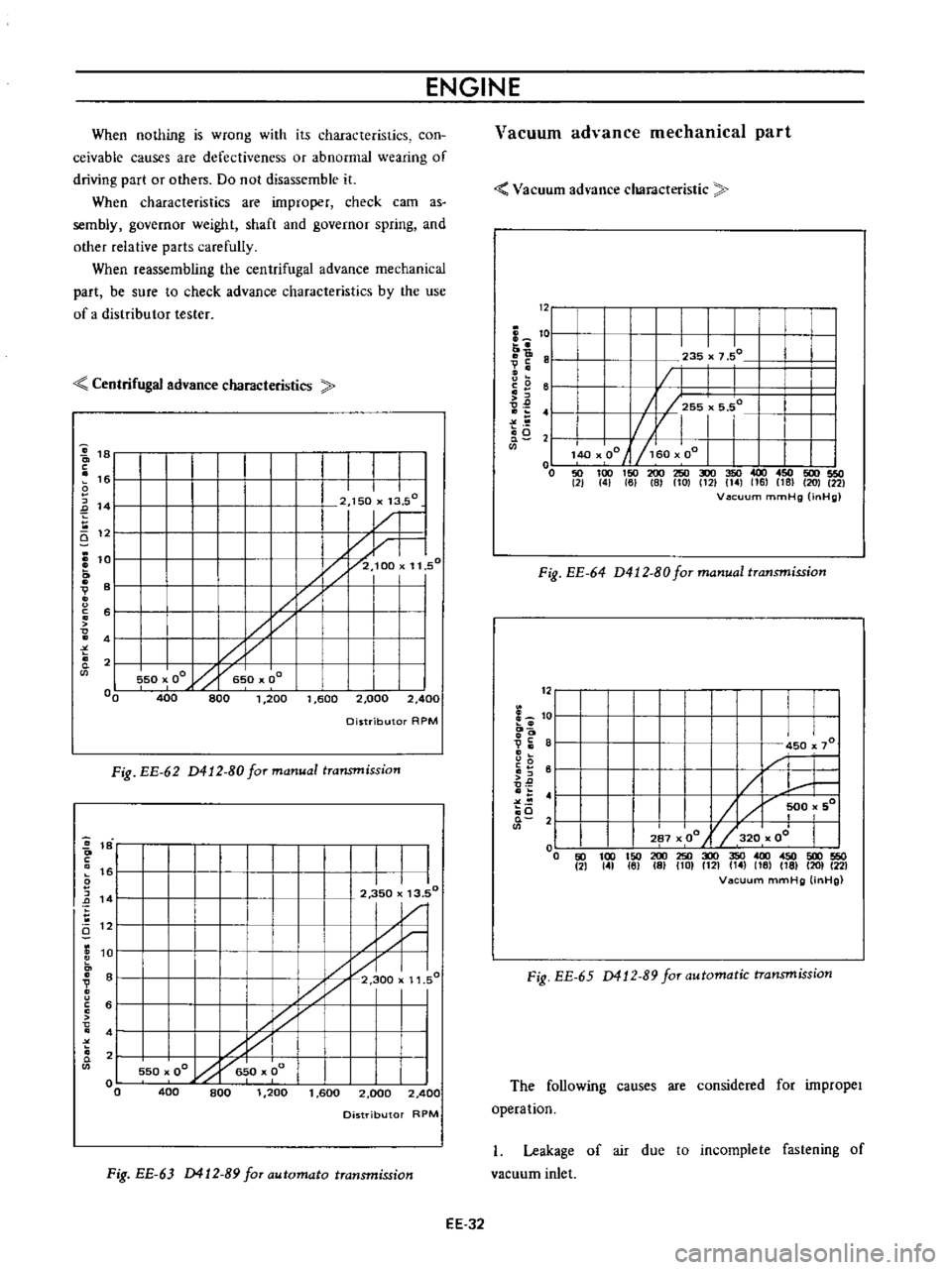
Centrifugal
advance
characteristics
1
c
1
Ei
12
L
o
V
o
u
c
o
o
t
D
c
s
151
14
e
101
0
81
V
0
u
c
51
0
41
t
0
Q
2
01
0
I
I
I
1
rj
11
50
I
J
2
100
50
oQ
5
00
400
800
1
200
1
600
2
00
Distributor
RPM
Fig
EE
62
D412
80formanual
transmission
I
I
I
2
350
13
50
1
1
1
300
1
1
550
00
h
6
0
0
I
400
800
1
200
1
600
2
000
Distributor
RPM
Fig
EE
63
D412
B9
faT
automata
transmission
2
400
I
11
50
2
400
EE
32
Vacuum
advance
mechanical
part
Vacuum
ad
ance
characteristic
12
I
I
I
I
I
II1
5515
5Q
i
01
40
00
i1j
50
00
1
I
o
50
100
150
200
250
300
350
400
450
500
550
21
41
6
8
101
C121
141
161
181
201
22
V2Icuum
mmHg
inHg
I
I
I
I
7
50
1
1Q
Ii
V
I
o
0
u
i
e
6
tI
2
o
i5
0
235
Fig
EE
64
D412
80
for
manual
transmission
c
1
0
I
o
9i
8
o
u
0
i
61
0
0
0
4
o
Q
2
I
I
I
450
x
70
L
H
1
500
501
287
00
l
320
oJ
I
I
200250300350400450500550
IS
101
1121
t4
16
16
1201
22
Vacuum
mmHg
OnHg
o
50
100
150
2
141
161
Fig
EE
65
0412
89
for
automatic
transmission
The
following
causes
are
considered
for
impropeI
opera
tion
I
Leakage
of
air
due
to
incomplete
fastening
of
vacuum
inlet
Page 455 of 513
ENGINE
ElECTRICAL
SYSTEM
SPECIFICATIONS
AND
SERVICE
DATA
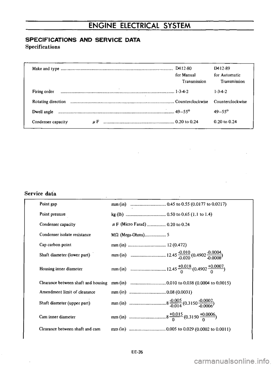
Specifications
Make
and
type
0412
80
0412
89
for
Manual
for
Automatic
Transmission
Transmission
Firing
order
1
3
4
2
I
3
4
2
Rotating
direction
Counterclockwise
Counterclockwise
Dwell
angle
49
550
49
550
Condenser
capacity
J
lF
0
20
to
0
24
0
20
to
0
24
Service
data
Point
gap
mm
in
0
45
to
0
55
0
0177
to
0
0217
0
50
to
0
65
1
1
to
1
4
Point
pressure
kg
lb
Condenser
capacity
p
F
Micro
Farad
0
20
to
0
24
Condenser
isolate
resistance
M
1
Mega
Ohms
5
Cap
carbon
point
mm
in
rom
in
Housing
inner
diameter
mm
in
12
0
472
0
010
D
0004
12
45
0
020
0
4902
D
0008
12
45
018
0
4902
0007
Shaft
diameter
lower
part
Clearance
between
shaft
and
housing
mm
in
Amendment
limit
of
clearance
mm
in
0
010
to
0
Q38
0
0004
to
0
0015
0
08
0
0031
8
0
005
0
3150
0
0002
D
O
14
D
0006
8
O
15
0
3150
0006
0
005
to
0
029
0
0002
to
0
00
II
Shaft
diameter
upper
part
mm
in
earn
inner
diameter
rom
in
Clearance
between
shaft
and
cam
mm
in
EE
35
Page 466 of 513
ENGINE
REMOVAL
INSTAllATION
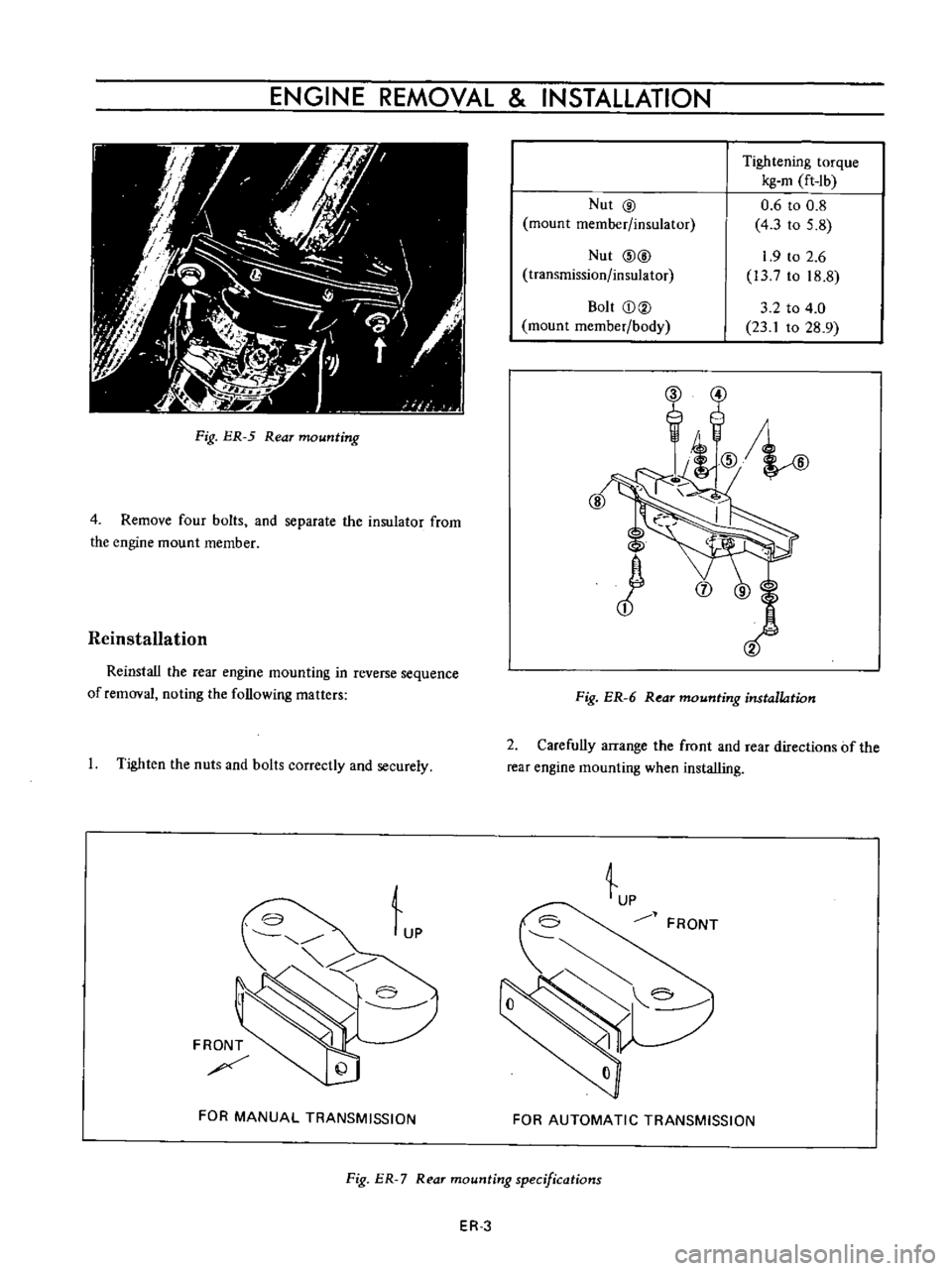
Fig
ER
5
Rear
mounting
4
Remove
four
bolts
and
separate
the
insulator
from
the
engine
mount
member
Reinstallation
Reinstall
the
rear
engine
mounting
in
reverse
sequence
of
removal
noting
the
following
matters
I
Tighten
the
nuts
and
bolts
correctly
and
securely
Lp
FRONT
FOR
MANUAL
TRANSMISSION
Nut
@
mount
member
insulator
Nut
@@
transmission
insulator
Bolt
CD@
mount
member
body
Tightening
torque
kg
m
ft
Ib
0
6
to
0
8
4
3
to
5
8
1
9
to
2
6
l3
to
18
8
3
2
to
4
0
23
1
to
28
9
Fig
ER
6
Rear
mounting
installation
2
Carefully
arrange
the
front
and
rear
directions
of
the
rear
engine
mounting
when
installing
tp
FRONT
FOR
AUTOMATIC
TRANSMISSION
Fig
ER
7
R
ar
mounting
specifications
ER
3
Page 488 of 513
TRANSMISSION
TRANSMISSION
CONTENTS
DESCRIPTION
Specifications
REMOVAL
DISASSEMBLY
INSPECTION
Transmission
case
and
rear
extension
Bearing
Gear
and
shaft
TM
l
TM
l
TM
2
TM
4
TM
7
TM
7
TM
8
TM
8
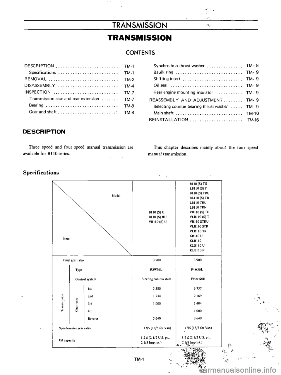
DESCRIPTION
Three
speed
and
four
speed
manual
transmission
are
available
for
BJ
10
series
Specifications
Model
Item
Finalgear
atio
Type
Control
ystem
nd
J
d
4th
Rever
Speedometer
gear
aHo
Oil
apacity
TM
8
TM
9
TM
9
TM
9
TM
9
TM
9
TM
9
TM
l0
TM
16
Synchro
hub
thrust
washer
Baulk
ring
Shilting
insert
Oil
seal
Rear
engine
mounting
insulator
REASSEMBLY
AND
ADJUSTMENT
Selecting
counter
bearing
thrust
washer
Main
shaft
REINSTALLATION
This
chapter
describes
mainly
about
the
four
speed
manual
transmission
811O
5
U
8110
5
RU
VBIIO
S
U
3
900
R3W56L
Steering
olumn
shift
3
380
1
734
1
000
3
640
17
5
18
5
for
Van
I
2l
2
1
2
U
S
pl
1
8
Imp
pc
TM
l
BIIO
S
TU
LB110
S
T
BllO
5
TRU
DUlO
5
TR
L8110
TRU
L8110
TRN
VBllO
S
TU
VLBllO
5
T
VBllO
SIRU
VLBllO
SIR
VLBllO
TR
KBIIO
U
KLBllO
KLBllO
U
KLBI
O
N
3
900
F4W56L
Floor
shift
3
757
69
1
404
1
000
3
640
17
5
18
5
for
Van
i
r
i
1
2
t
2
1
2
U
S
pt
IJ8Imp
pt
l
OC
t
1
I
t
y
y
dt
k
J
t
i
r
Page 503 of 513
CHASSIS
REINSTALLATION
Remount
the
transmission
in
reverse
sequence
of
dismounting
TRANSMISSION
GEAR
CONTROL
CONTENTS
DESCRIPTION
COLUMN
SHIFT
CONTROL
SYSTEM
Removal
TM
16
TM
17
TM
17
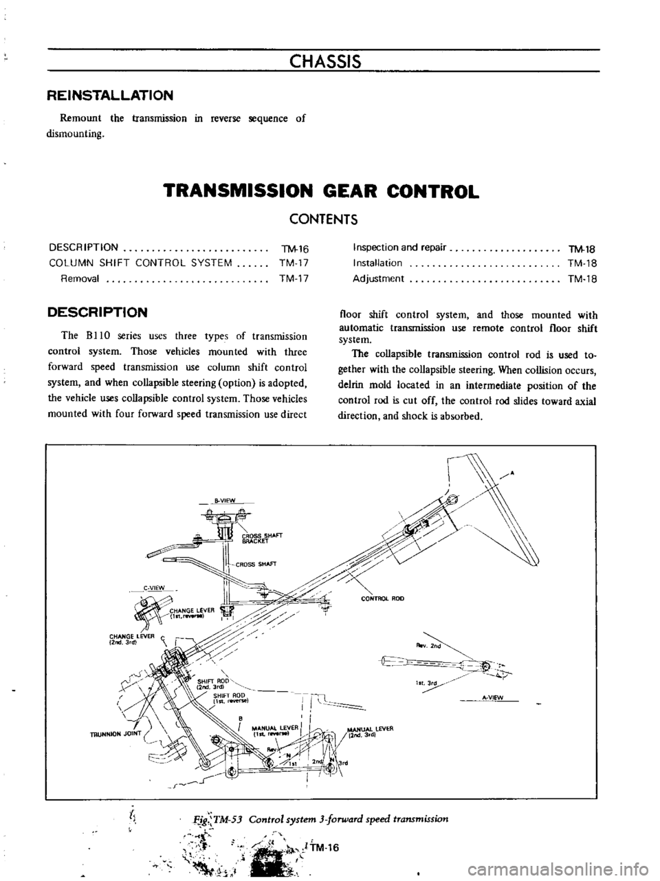
DESCRIPTION
The
B
10
series
uses
three
types
of
transmission
control
system
Those
vehicles
mounted
with
three
forward
speed
transmission
use
column
shift
control
system
and
when
collapsible
steering
option
is
adopted
the
vehicle
uses
collapsible
control
system
Those
vehicles
mounted
with
four
forward
speed
transmission
use
direct
B
VIEW
CROSS
SHAFT
BRACKET
CROSS
SHAfT
C
VIEW
HANGE
LEVER
l
rwIl
CHANGE
LEVER
C
2
3rdl
r
X
h
Inspection
and
repair
Installation
Adjustment
TM
18
TM
18
TM
18
floor
shift
control
system
and
those
mounted
with
automatic
transmission
use
remote
control
floor
shift
system
The
collapsible
transmission
control
rod
is
used
to
gether
with
the
collapsible
steering
When
collision
occurs
delrin
mold
located
in
an
intermediate
position
of
the
control
rod
is
cut
off
the
control
rod
slides
toward
axial
direction
and
shock
is
absorbed
c
0
CONTROL
ROD
r
A
v
t
c
t
IT
Ii
A
VIEW
MANUAL
LEVER
II
l
MANUAl
lEVER
11st
r
lW1
11nd3rd
IIooV
j
II
1
0SI
2nd
Jrd
I
I
j
tl
Control
system
3
forward
speed
transmission
Ffg
TM
53
t
f
Voo
1
ITM
16
Page 505 of 513
CHASSIS
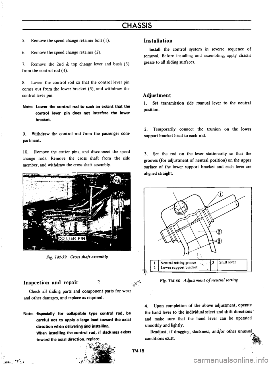
5
Remove
the
speed
change
retainer
bolt
I
6
Remove
the
speed
change
retainer
2
7
Remove
the
2nd
top
change
lever
and
bush
13
from
the
control
rod
4
8
Lower
the
control
rod
so
that
the
control
lever
pin
comes
out
from
the
lower
bracket
5
and
withdraw
the
control
lever
pin
Note
low
the
control
rod
to
such
an
extent
that
the
con
b
ol
lever
pin
does
not
interfere
the
lower
bracket
9
Withdraw
the
control
rod
from
the
passenger
com
partment
10
Remove
the
cotter
pins
and
disconnect
the
speed
change
rods
Remove
the
cross
shaft
from
the
side
member
and
withdraw
the
cross
shaft
assembly
Fig
TM
59
Cross
shaft
assembly
Inspection
and
repair
Check
all
sliding
parts
and
component
parts
for
wear
and
other
damages
and
replace
as
required
Note
Especially
for
collapsible
type
control
rod
be
careful
not
to
apply
a
large
load
toward
the
axial
direction
when
delivering
and
installing
When
installing
the
control
rod
if
slackness
exists
toward
the
axial
direction
replace
S
i
TM
18
C
1
rr
i
Al
Installation
Install
the
control
system
in
reverse
sequence
of
removal
Before
installing
and
assembling
apply
chassis
grease
to
all
sliding
surfaces
Adjustment
I
Set
transmission
side
manual
lever
to
the
neutral
position
2
Temporarily
connect
the
trunion
on
the
lower
support
bracket
head
to
each
rod
3
Set
the
rod
on
the
lever
stationarily
so
that
the
grooves
for
adjustment
of
neutral
position
on
the
upper
surface
of
the
lower
support
bracket
and
each
lever
are
aligned
straight
t
I
Neutral
setting
groove
2
Lower
support
bracket
13
I
Shift
lever
Fig
TM
60
Adjustment
of
neutral
setting
4
Upon
completion
of
the
above
adjustment
operate
the
hand
lever
to
the
individual
select
and
shift
directions
and
make
sure
that
the
hand
lever
can
be
operated
smoothly
and
lightly
Readjust
if
dragging
slackness
and
or
other
unusual
conditions
exist