1973 DATSUN B110 manual transmission
[x] Cancel search: manual transmissionPage 318 of 513
EMISSION
CONTROL
AND
TUNE
UP
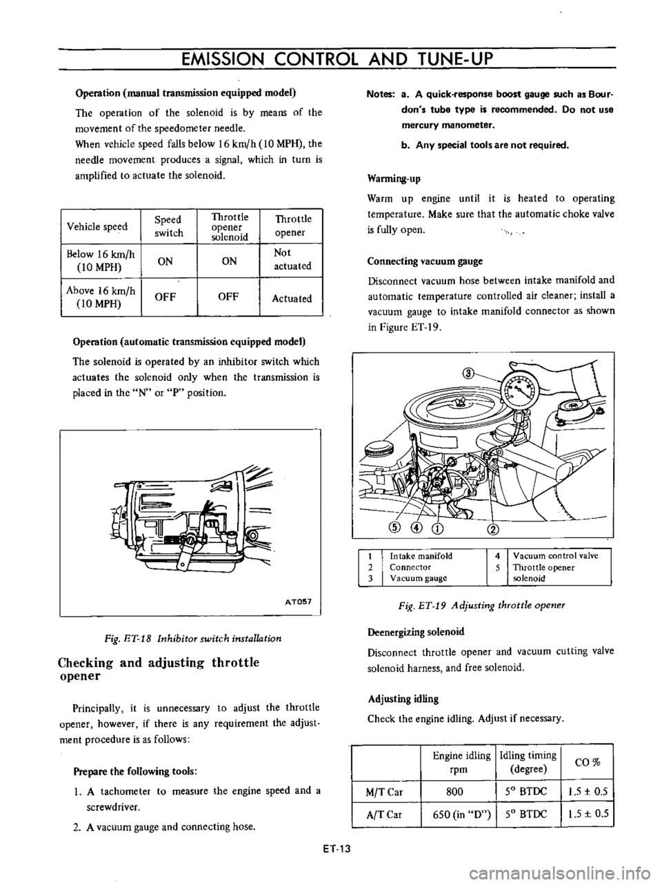
Operation
manual
transmission
equipped
model
The
operation
of
the
solenoid
is
by
means
of
the
movement
of
the
speedometer
needle
When
vehicle
speed
falls
below
16
km
h
10
MPH
the
needle
movement
produces
a
signal
which
in
turn
is
amplified
to
actuate
the
solenoid
I
Vehicle
speed
Speed
Throttle
Throttle
switch
opener
opener
solenoid
Below
16
km
h
Not
10
MPH
ON
ON
actuated
Above
16
km
h
OFF
OFF
Actuated
10
MPH
Operation
automatic
transmission
equipped
model
The
solenoid
is
operated
by
an
inhibitor
switch
which
actuates
the
solenoid
only
when
the
transmission
is
placed
in
the
N
or
P
position
c
fil
rn
AT057
Fig
ET
18
Inhibitor
switch
installation
Checking
and
adjusting
throttle
opener
Principally
it
is
unnecessary
to
adjust
the
throttle
opener
however
if
there
is
any
requirement
the
adjust
ment
procedure
is
as
follows
Prepare
the
following
tools
1
A
tachometer
to
measure
the
engine
speed
and
a
screwdriver
2
A
vacuum
gauge
and
connecting
hose
ET
13
Notes
a
A
quick
response
boost
gauge
such
as
Bour
don
s
tube
type
is
recommended
Do
not
use
mercury
manometer
b
Any
special
tools
are
not
required
Warming
up
Warm
up
engine
until
it
is
heated
to
operating
temperature
Make
sure
that
the
automatic
choke
valve
is
fully
open
Connecting
vacuum
gauge
Disconnect
vacuum
hose
between
intake
manifold
and
automatic
temperature
controlled
air
cleaner
install
a
vacuum
gauge
to
intake
manifold
connector
as
shown
in
Figure
ET
19
1
Intake
manifold
2
Connector
3
Vacuum
gauge
4
Vacuum
control
valve
5
Throttle
opener
solenoid
Fig
ET
19
Adjusting
throttle
opener
Deenergizing
solenoid
Disconnect
throttle
opener
and
vacuum
cutting
valve
solenoid
harness
and
free
solenoid
Adjusting
idling
Check
the
engine
idling
Adjust
if
necessary
Engine
idling
rpm
Idling
timing
I
CO
degree
SO
BTDC
I
L51c0
5
SO
BTDC
I
I
S
1c
0
5
M
T
Car
A
TCar
800
6S0
in
D
Page 323 of 513
ENGINE
Gear
Vacuum
advance
Note
R
No
1st
No
2nd
No
3rd
No
4th
Yes
Immediately
after
starting
the
engine
in
cold
weather
vacuum
advance
is
available
for
all
gear
positions
A12
Engine
with
Manual
Transmission
Distributor
Ignition
switch
8
1
J
Battery
Thermo
switch
9
Transmission
L
r
l
r
Vacuum
advance
unit
To
carburetor
Needle
valve
OFF
l
To
air
cleaner
ON
Vacuum
cutting
valve
solenoid
Top
switch
Top
off
I
7
1
OFF
Vacuum
actuated
ON
Vacuum
eminated
into
atmosphere
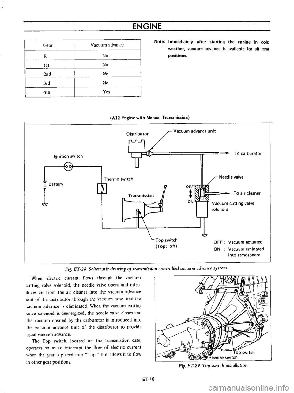
Fig
ET
28
Schematic
drawing
of
transmission
controlled
vacuum
advance
system
When
electric
current
flows
through
the
vacuum
cutting
valve
solenoid
the
needle
valve
opens
and
intro
duces
air
from
the
air
cleaner
into
the
vacuum
advance
unit
of
the
distributor
through
the
vacuum
hose
and
the
vacuum
advance
is
eliminated
When
the
vacuum
cutting
valve
solenoid
is
deenergized
the
needle
valve
closes
and
the
vacuum
created
by
the
carburetor
is
introduced
into
the
vacuum
advance
unit
of
the
distributor
to
provide
usual
vacuum
advance
The
Top
switch
located
on
the
transmission
case
operates
so
as
to
interrupt
the
flow
of
electric
current
when
the
gear
is
placed
into
Top
but
allows
it
to
flow
in
other
gear
positions
Fig
ET
29
Top
switch
installation
ET
18
Page 331 of 513

ENGINE
Spark
plugs
Cap
mm
in
0
8
to
0
9
0
03110
0
035
Idle
CO
ldie
speed
Manual
transmission
rpm
rpm
1
5
to
5
800
1
5
to
5
650
in
D
position
Automatic
transmission
Dash
pot
Setting
engine
speed
rpm
1
900
to
2
000
Throttle
opener
at
sea
level
Setting
vacuwn
pressure
Manual
transmission
Automatic
transmission
Setting
engine
speed
no
load
Servo
diaphragm
full
stroke
rpm
mm
in
500
to
540
19
7
to
21
3
480
to
520
18
9
to
20
5
1
650
to
1
850
5
0
1969
mmHg
in
Hg
mmHg
in
Hg
Theono
switch
Temperature
rises
from
low
to
high
oC
0
F
above
5
41
Flow
guide
valve
Opera
ting
pressure
mmHg
in
Hg
10
0
4
TROUBLE
DIAGNOSES
AND
CORRECTIONS
Troubles
Possible
causes
Remedies
CANNOT
CRANK
ENGINE
OR
SLOW
CRANKING
Improper
grade
oiL
Replace
with
proper
grade
oiL
Discharged
battery
Charge
battery
Defective
battery
Replace
Loosen
fan
belt
Adjust
Trouble
in
charge
system
Inspect
charge
system
Wiring
connection
trouble
in
starting
circuit
Correct
Defective
starter
switch
Repair
or
replace
Defective
starter
motor
Repair
or
replace
ET
26
I
Page 373 of 513

ENGINE
MECHANICAL
SERVICE
DATA
AND
SPECIFICATIONS
GENERAL
SPECIFICATION
Cylinder
arrangement
4
in
line
Displacement
cc
cu
in
mm
in
1
171
71
5
73
x
70
2
874
x
2
756
Bore
and
stroke
Valve
arrangemen
t
Over
head
valve
Firing
order
I
3
4
2
Engine
idle
rpm
800
Manual
transmission
650in
D
Automatic
transmission
Compression
ratio
8
5
Oil
pressure
Hot
at
2
000
rpm
kgfcm2
Ibfsq
in
3
0
to
3
5
43
to
50
TIGHTENING
TORQUE
Unit
kg
m
ft
lb
Cylinder
head
bolts
Flywheel
bolts
5
5
to
6
0
40
to
43
3
2
to
3
8
23
to
28
6
5
to
7
5
47
to
54
5
0
to
6
0
36
to
43
4
0
to
4
8
29
to
35
0
4
to
0
6
2
9
to
4
3
l
l
to
I
7
8
0
to
12
0
9
to
I
4
6
5
to
10
15
to
16
108
to
116
Connecting
rod
nuts
Main
bearing
cap
bolts
Camshaft
gear
bolts
Oil
pan
bolts
Oil
pump
bolts
Oil
strainer
bolts
Crank
pulley
bolts
EM
33
Page 400 of 513
FUEl
SYSTEM
Secondary
throttle
valve
is
operated
by
throttle
lever
The
high
power
and
good
acceleration
are
gained
with
combination
of
the
auxiliary
valve
2
Accelerating
pump
gives
excellent
acceleration
3
The
power
valve
mechanism
is
of
a
vacuum
actuated
boost
type
and
improves
high
speed
driving
4
The
throttle
opener
control
system
Refer
to
Section
ET
incorporates
a
servo
diaphragm
The
servo
dia
phragm
helps
open
the
throttle
valve
at
a
decreasing
speed
so
as
to
reduce
the
emission
of
hydrocarbons
to
a
minimum
5
An
anti
dieseling
solenoid
is
used
as
a
means
of
preventing
dieseling
When
the
ignition
key
is
turned
off
the
fuel
passage
involved
in
the
slow
system
is
closed
and
the
fuel
supply
is
shut
down
completely
6
In
the
choke
mechanism
an
electric
automatic
choke
is
used
to
automatically
control
the
choke
valve
operation
during
the
warm
up
of
the
engine
7
The
carburetor
for
automatic
transmission
is
equipped
with
so
called
dash
pot
that
is
it
makes
smooth
decelerating
without
engine
stall
at
any
operating
condi
tion
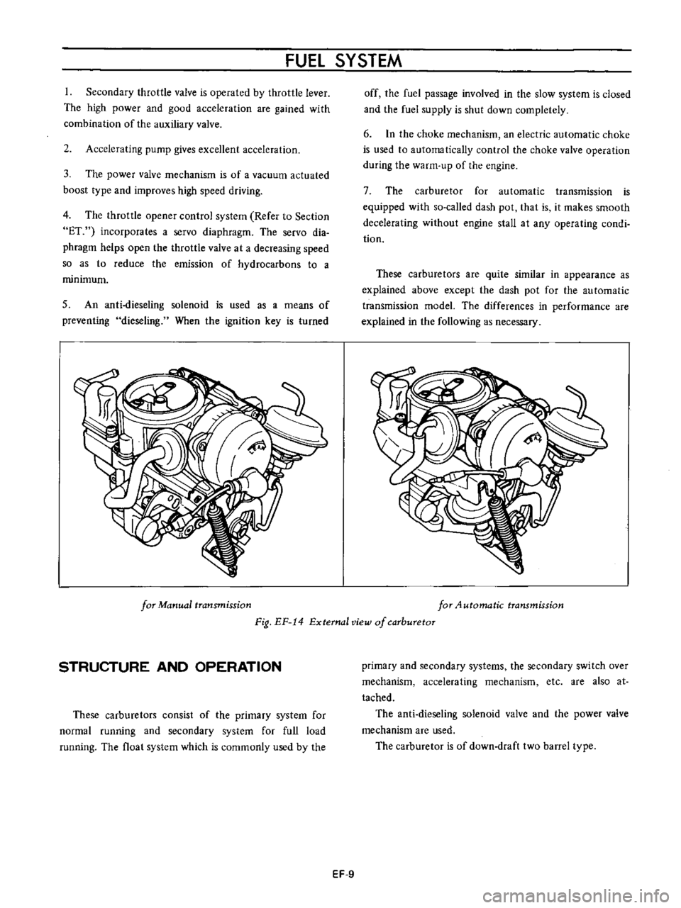
These
carburetors
are
quite
similar
in
appearance
as
explained
above
except
the
dash
pot
for
the
au
tomatic
transmission
model
The
differences
in
performance
are
explained
in
the
following
as
necessary
for
Manual
transmission
for
4utomatic
transmission
Fig
EF
14
External
view
of
carburetor
STRUCTURE
AND
OPERATION
These
carburetors
consist
of
the
primary
system
for
normal
running
and
secondary
system
for
full
load
running
The
float
system
which
is
commonly
used
by
the
primary
and
secondary
systems
the
secondary
switch
over
mechanism
accelerating
mechanism
etc
are
also
at
tached
The
anti
dieseling
solenoid
valve
and
the
power
valve
mechanism
are
used
The
carburetor
is
of
down
draft
two
barrel
type
EF
9
Page 406 of 513
CD
r
Fuel
level
adjustment
@
@
It
I
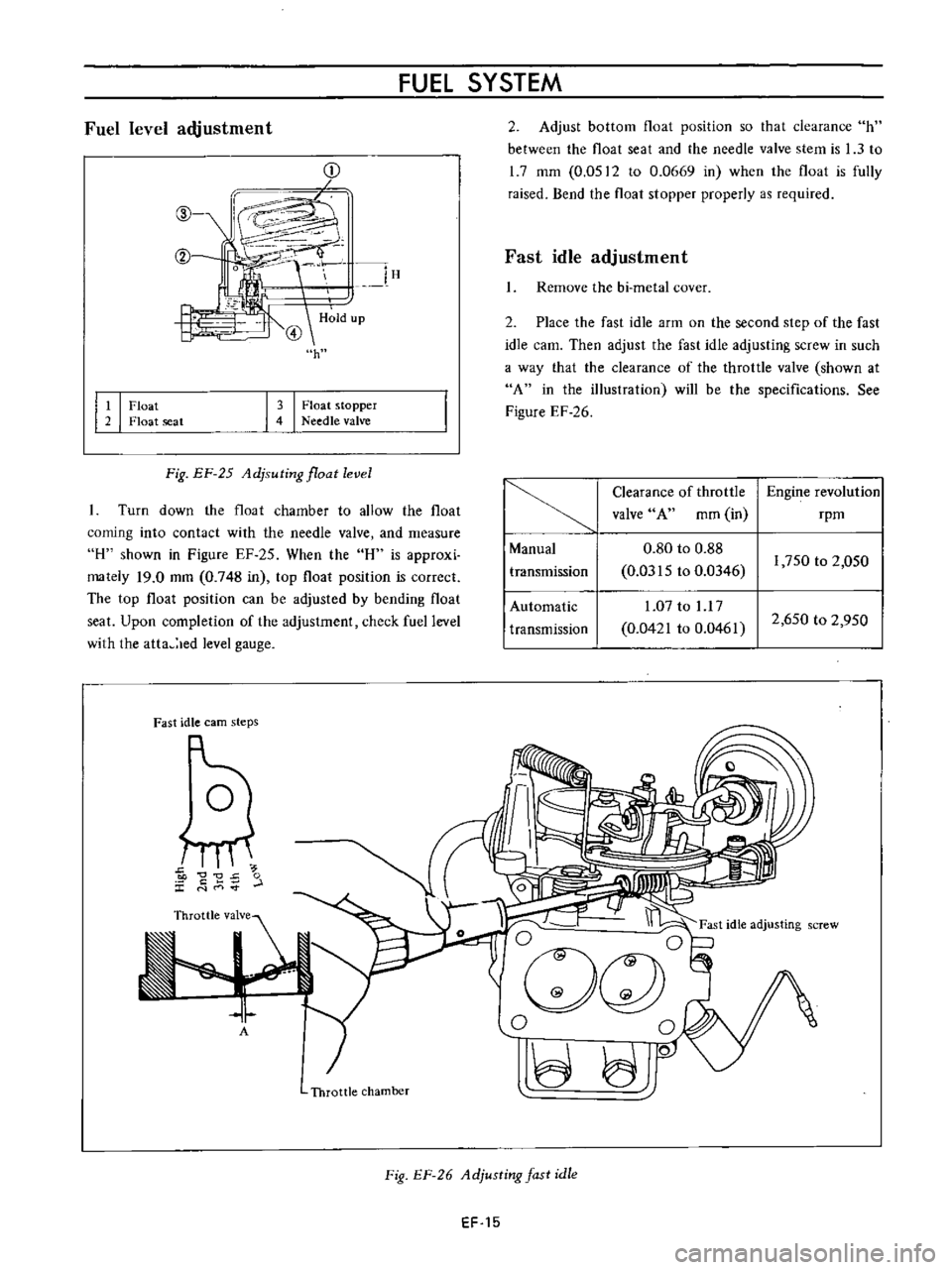
Float
2
Float
seat
FUEL
SYSTEM
2
Adjust
bottom
float
position
so
that
clearance
h
between
the
float
seat
and
the
needle
valve
stem
is
1
3
to
1
7
mm
0
0512
to
0
0669
in
when
the
float
is
fully
raised
Bend
the
float
stopper
properly
as
required
l
lH
H
ld
up
@
h
Fast
idle
adjustment
Remove
the
bi
metal
cover
3
I
Float
stopper
4
Needle
valve
2
Place
the
fast
idle
arm
on
the
second
step
of
the
fast
idle
earn
Then
adjust
the
fast
idle
adjusting
screw
in
such
a
way
that
the
clearance
of
the
throttle
valve
shown
at
A
in
the
illustration
will
be
the
specifications
See
Figure
EF
26
Fig
EF
25
Adjsuting
float
level
Turn
down
the
float
chamber
to
allow
the
float
coming
into
contact
with
the
needle
valve
and
measure
H
shown
in
Figure
EF
25
When
the
H
is
approxi
mately
19
0
mm
0
748
in
top
float
position
is
correct
The
top
float
position
can
be
adjusted
by
bending
float
seat
Upon
completion
of
the
adjustment
check
fuel
level
with
the
atta
led
level
gauge
Clearance
of
throttle
Engine
revolution
valve
A
mm
in
rpm
Manual
0
80
to
0
88
transmission
0
0315
to
0
0346
1
750
to
2
050
Automatic
1
07
to
l
l
7
transmission
0
0421
to
0
0461
2
650
to
2
950
Fast
idle
earn
steps
5
C
0
J
t
E
r
L
E
I
I
Ogc
l
0
0
JO
A
Throttle
chamber
Fig
EF
26
Adjusting
fast
idle
EF
15
Page 407 of 513
ENGINE
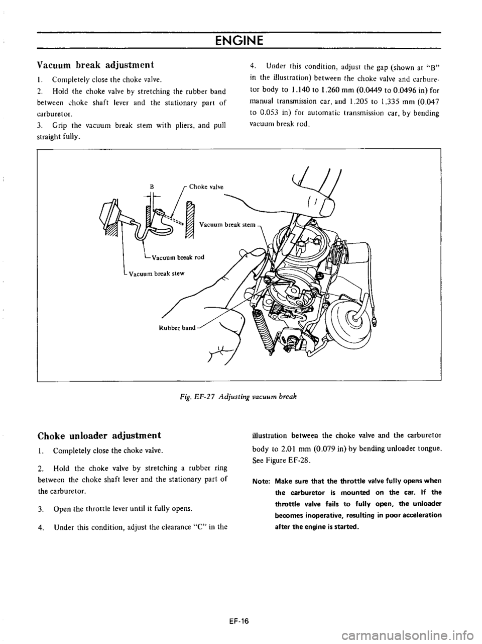
Vacuum
break
adjustment
I
Completely
close
the
chuke
valve
2
Hold
the
choke
valve
by
stretching
the
rubber
band
between
hoke
shaft
lever
and
the
sta
tionary
part
of
carburetor
3
Grip
the
vacuum
break
stem
with
pliers
and
pull
straight
fully
Vacuum
break
rod
Vacuum
break
stew
Rubber
band
4
Under
this
condition
adjust
the
gap
shown
at
B
in
the
illustration
between
the
choke
valve
and
carbure
tor
body
to
1
140
to
1
260
mm
0
0449
to
0
0496
in
for
manual
transmission
car
and
1
205
to
1
335
mm
0
047
to
0
053
in
for
automatic
transmission
car
by
bending
vacuum
break
rod
I
Fig
EF
27
Adjusting
vacuum
break
Choke
un
loader
adjustment
I
Completely
close
the
choke
valve
2
Hold
the
choke
valve
by
stretching
a
rubber
ring
between
the
choke
shaft
lever
and
the
stationary
part
of
the
carburetor
3
Open
the
throttle
lever
until
it
fully
opens
4
Under
this
condition
adjust
the
clearance
C
in
the
illustration
between
the
choke
valve
and
the
carburetor
body
to
2
01
mm
0
079
in
by
bending
unloader
tongue
See
Figure
EF
28
Note
Make
sure
that
the
throttle
valve
fully
opens
when
the
carburetor
is
mounted
on
the
car
If
the
throttle
valve
fails
to
fully
open
the
unloader
becomes
inoperative
resulting
in
poor
acceleration
after
the
engine
is
started
EF
16
Page 412 of 513
FUEL
SYSTEM
5
Check
venturi
clusters
for
loose
or
worn
parts
If
damage
or
looseness
exists
replace
cluster
assembly
6
Check
the
linkage
for
operating
condition
7
Inspect
the
operation
of
accelerating
pump
Pour
gasoline
into
the
float
chamber
and
operate
the
throttle
lever
Check
condition
of
gasoline
injection
from
the
accelerating
nozzle
Assembly
and
instalIetion
Assemble
and
install
the
carburetor
in
reverse
sequence
of
disassembly
and
removal
Replace
the
gaskets
if
necessary
When
disassembling
and
reassembling
the
interlock
link
and
related
components
be
careful
not
to
bend
or
deform
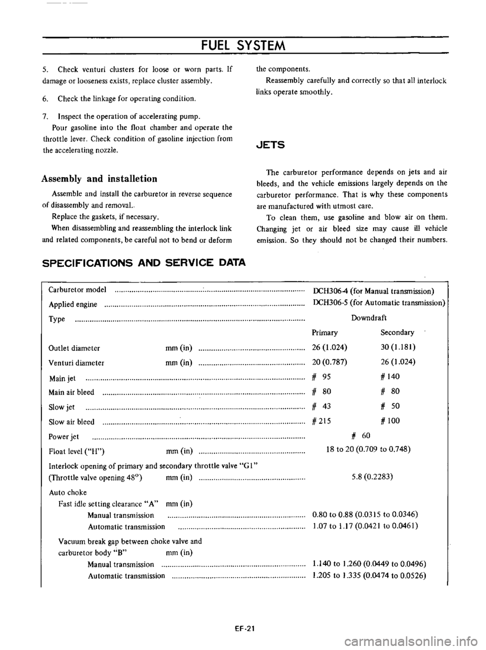
SPECIFICATIONS
AND
SERVICE
DATA
Carburetor
model
Applied
engine
Type
Outlet
diameter
mm
in
rom
in
Venturi
diameter
Main
jet
Main
air
bleed
Slow
jet
Slow
air
bleed
Power
jet
Float
level
H
rom
in
Interlock
opening
of
primary
and
secondary
throttle
valve
G
I
Throttle
valve
opening
480
mm
in
Auto
choke
Fast
idle
setting
clearance
A
mm
in
Manual
transmission
Automatic
transmission
Vacuum
break
gap
between
choke
valve
and
carburetor
body
8
mm
in
Manual
transmission
Automatic
transmission
EF
21
the
components
Reassembly
carefully
and
correctly
so
that
all
interlock
links
operate
smoothly
JETS
The
carburetor
performance
depends
on
jets
and
air
bleeds
and
the
vehicle
emissions
largely
depends
on
the
carburetor
performance
That
is
why
these
components
are
manufactured
with
utmost
care
To
clean
them
use
gasoline
and
blow
air
on
them
Changing
jet
or
air
bleed
size
may
cause
ill
vehicle
emission
So
they
should
not
be
changed
their
numbers
DCH3064
for
Manual
transmission
DCH306
5
for
Automatic
transmission
Downdraft
Primary
Secondary
26
1
024
30
1
181
20
0
787
26
1
024
1
95
1
140
1
80
1
80
1
43
1
50
1
215
1
100
1
60
18
to
20
0
709
to
0
748
5
8
0
2283
0
80
to
0
88
0
0315
to
0
0346
1
07
to
1
17
0
0421
to
0
0461
1
140
to
1
260
0
0449
to
0
0496
1
205
to
1
335
0
0474
to
0
0526