1973 DATSUN B110 manual transmission
[x] Cancel search: manual transmissionPage 58 of 513
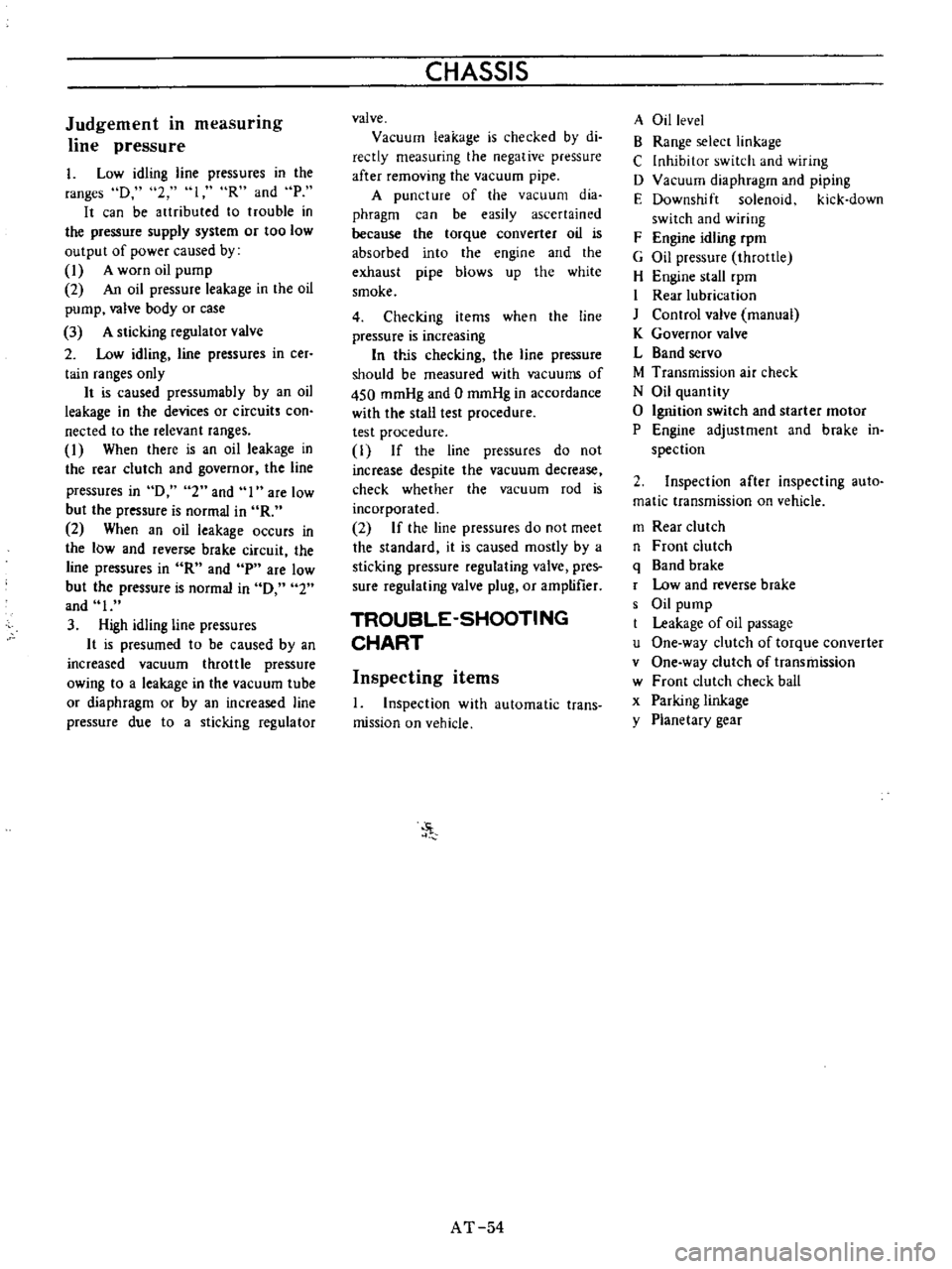
Judgement
in
measurmg
line
pressure
I
Low
idling
line
pressures
in
the
ranges
D
2
loR
and
P
It
can
be
artributed
to
trouble
in
the
pressure
supply
system
or
too
low
output
of
power
caused
by
1
A
worn
oil
pump
2
An
oil
pressure
leakage
in
the
oil
pump
valve
body
or
case
3
A
sticking
regulator
valve
2
Low
idling
line
pressures
in
cer
tain
ranges
only
It
is
caused
pressumabIy
by
an
oil
leakage
in
the
devices
or
circuits
con
nected
to
the
relevant
ranges
1
When
there
is
an
oil
leakage
in
the
rear
clutch
and
governor
the
line
pressures
in
D
2
and
I
are
low
but
the
pressure
is
normal
in
R
2
When
an
oil
leakage
occurs
in
the
low
and
reverse
brake
circuit
the
line
pressures
in
R
and
p
are
low
but
the
pressure
is
normal
in
0
2
and
I
3
High
idling
line
pressures
It
is
presumed
to
be
caused
by
an
increased
vacuum
throttle
pressure
owing
to
a
leakage
in
the
vacuum
tube
or
diaphragm
or
by
an
increased
line
pressure
due
to
a
sticking
regulator
CHASSIS
valve
Vacuum
leakage
is
checked
by
di
reetly
measuring
the
negative
pressure
after
removing
the
vacuum
pipe
A
puncture
of
the
vacuum
dia
phragm
can
be
easily
ascertained
because
the
torque
converter
oil
is
absorbed
into
the
engine
and
the
exhaust
pipe
blows
up
the
white
smoke
4
Checking
items
when
the
line
pressure
is
increasing
In
trJs
checking
the
line
pressure
should
be
measured
with
vacuums
of
450
mmHg
and
0
mmHg
in
accordance
with
the
stall
test
procedure
test
procedure
1
If
the
line
pressures
do
not
increase
despite
the
vacuum
decrease
check
whether
the
vacuum
rod
is
incorporated
2
If
the
line
pressures
do
not
meet
the
standard
it
is
caused
mostly
by
a
sticking
pressure
regulating
valve
pres
sure
regulating
valve
plug
or
amptifier
TROUBLE
SHOOTING
CHART
Inspecting
items
1
Inspection
with
automatic
trans
mission
on
vehicle
J
AT
54
A
Oil
level
B
Range
selecr
linkage
C
Inhibitor
switch
and
wiring
D
Vacuum
diaphragm
and
piping
E
Downshift
solenoid
kick
down
switch
and
wiring
F
Engine
idling
rpm
G
Oil
pressure
throttle
H
Engine
stall
rpm
I
Rear
lubrication
J
Control
valve
manual
K
Governor
valve
L
Band
servo
M
Transmission
air
check
N
Oil
quantity
o
Ignition
switch
and
starter
motor
P
Engine
adjustment
and
brake
in
spection
2
Inspection
after
inspecting
auto
matic
transmission
on
vehicle
m
Rear
clutch
n
Front
clutch
q
Band
brake
r
Low
and
reverse
brake
s
Oil
pump
Leakage
of
oil
passage
u
One
way
clutch
of
torque
converter
v
One
way
clutch
of
transmission
w
Front
clutch
check
ball
x
Parking
linkage
y
Planetary
gear
Page 66 of 513
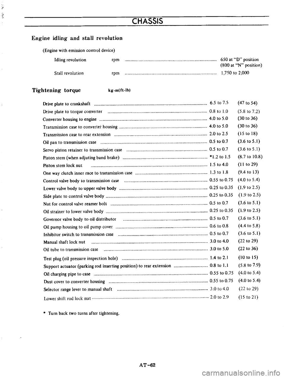
CHASSIS
Engine
idling
and
stall
revolution
Engine
with
emission
control
device
Idling
revolution
rpm
650
at
0
position
800
at
N
position
1
750
to
2
000
Stall
revolution
rpm
Tightening
torque
kg
m
ft
Ib
Test
plug
oil
pressure
inspection
hole
Support
actuator
parking
rod
inserting
position
to
rear
extension
Oil
charging
pipe
to
case
Dust
cover
to
converter
housing
Selector
range
lever
to
manual
shaft
Lower
shift
rod
lock
nut
6
5
t07
5
47
to
54
0
8
to
1
0
5
8
to
7
2
4
0
to
5
0
30
to
36
4
0
to
5
0
30
to
36
2
0
to
2
5
15
to
18
0
5
to
0
7
3
6
to
5
1
0
5
to
0
7
3
6toS
I
1
2
to
1
5
8
7
to
10
8
1
5
to
4
0
II
to
29
1
3
to
1
8
9
4
to
13
0
55
to
0
75
4
0
to
5
4
0
25
to
0
35
1
9
to
2
5
0
25
to
0
35
1
9
to
2
5
0
5
to
0
7
3
6
to
5
I
0
25
to
0
35
1
9
to
2
5
0
5
to
0
7
3
6
to
5
1
0
6
to
0
8
4
4
to
5
8
0
5
to
0
7
3
6
to
5
1
3
0
to
4
0
22
to
29
3
0
to
5
0
22
to
36
14
to
2
1
10
to
15
0
8
to
l
l
5
8
to
7
9
0
55
to
0
75
4
0
to
5
4
0
55
to
0
75
4
0
to
5
4
3
0
to
4
0
22
to
29
2
0
to
2
9
15
to
21
Drive
plate
to
crankshaft
Drive
plate
to
torque
converter
Converter
housing
to
engine
Transmission
case
to
converter
housing
Transmission
case
to
rear
extension
Oil
pan
to
transmission
case
Servo
piston
retainer
to
transmission
case
Piston
stem
when
adjuting
band
brake
Piston
stem
lock
nut
One
way
clutch
inner
race
to
transmission
case
Control
valve
body
to
transmission
case
Lower
valve
body
to
upper
valve
body
Side
plate
to
control
valve
body
Nut
for
control
valve
reamer
bolt
Oil
strainer
to
lower
valve
body
Governor
valve
body
to
oil
distributor
Oil
pump
housing
to
oil
pump
cover
Inhibitor
switch
to
transmh
sion
case
Manual
shaft
lock
nut
Oil
tube
to
transmission
case
Turn
back
two
turns
after
tightening
AT
62
Page 277 of 513
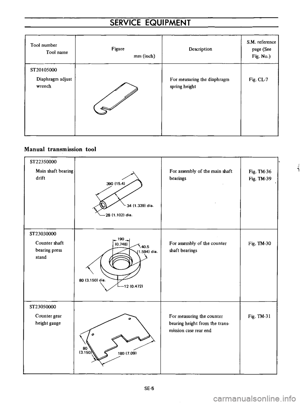
Tool
number
Tool
name
ST20105000
Diaphragm
adjust
wrench
SERVICE
EQUIPMENT
Figure
mm
inch
Manual
transmission
tool
ST22350000
Main
shaft
bearing
drift
ST23030000
Counter
shaft
bearing
press
stand
ST23050000
Counter
gear
height
gauge
SE
5
Description
For
measuring
the
diaphragm
spring
height
For
assembly
of
the
main
shaft
bearings
For
assembly
of
the
counter
shaft
bearings
For
measuring
the
counter
bearing
height
from
the
trans
mission
case
rear
end
S
M
reference
page
See
Fig
No
Fig
CL
7
Fig
TM
36
Fig
TM
39
Fig
TM
30
Fig
TM
31
Page 297 of 513
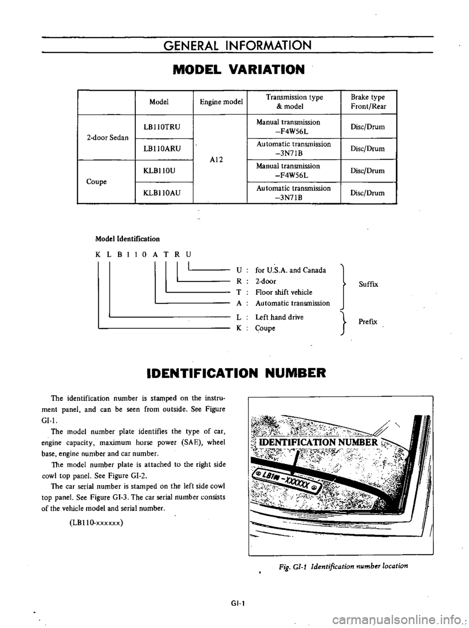
GENERAL
INFORMATION
MODEL
VARIATION
Model
Engine
model
Transmission
type
Brake
type
model
Front
Rear
LBllOTRU
Manual
transmission
Disc
Drum
F4W56L
2
door
Sedan
LBllOARU
Automatic
transmission
Disc
Drum
3N71B
AI2
KLBllOU
Manual
transmission
Disc
Drum
F4W56L
Coupe
Automatic
transmission
KLBllOAU
3N71B
Disc
Drum
Model
Identification
KLBIIOATRU
I
U
for
U
S
A
and
Canada
R
2
door
T
Floor
shift
vehicle
A
Automatic
transmission
L
Left
hand
drive
K
Coupe
SuffIx
PrefIx
IDENTIFICATION
NUMBER
The
identification
number
is
stamped
on
the
instru
ment
panel
and
can
be
seen
from
outside
See
Figure
GI
I
The
model
number
plate
identifles
the
type
of
car
engine
capacity
maximum
horse
power
SA
E
wheel
base
engine
number
and
car
number
The
model
number
plate
is
attached
to
the
right
side
cowl
top
panel
See
Figure
GI
2
The
car
serial
number
is
stamped
on
the
left
side
cowl
top
panel
See
Figure
GI
3
The
car
serial
number
consists
of
the
vehicle
model
and
serial
number
LBllO
xxxxxx
I
ll
r
N
t
0
S
k
j
c
ftr
o
l
l
r
2
0
IDENTIFICATION
NUMBER
l
r
f
N
s
r
F
i
u
I
Fig
GI
J
Identification
number
location
GI
l
Page 300 of 513

GENERAL
INFORMATION
spring
etc
support
the
rear
cruss
member
with
stands
In
other
cases
support
both
ends
of
the
rear
axle
housing
with
stands
Fig
CI
9
Rear
jacking
point
Fig
C
J
0
Rear
supportable
point
TOWING
Manual
transmission
model
When
the
car
is
towed
forward
connect
the
rope
securely
to
the
notched
portion
of
the
tension
rod
bracket
In
no
event
should
a
rope
be
applied
to
the
transverse
link
To
two
another
car
connect
a
rope
to
the
rear
shackle
of
rear
spring
Note
Avoid
applying
load
suddenly
to
a
rope
as
it
may
cause
damage
Fig
GI
l1
Front
towing
point
Fig
GI
12
Rear
towing
point
Automatic
transmission
model
The
car
may
be
towed
safely
on
its
rear
wheels
on
the
ground
with
the
select
lever
in
N
Neutral
position
of
at
speeds
of
less
than
30
km
h
18
7
MPH
However
the
propeller
shaft
must
be
disconnected
or
the
car
must
be
towed
on
its
front
wheels
on
the
ground
under
the
following
conditions
Tow
speed
of
more
than
30
kro
h
18
7
MPH
2
Car
must
be
towed
for
a
long
distance
over
10
km
or
6
miles
3
Transmission
is
not
operating
properly
If
car
is
towed
on
its
front
wheels
on
the
ground
the
GI
4
Page 301 of 513

GENERAL
INFORMATION
steering
wheel
should
be
secured
to
maintain
a
straight
ahead
position
TIE
DOWN
The
front
tie
down
hook
is
used
the
both
front
end
of
tension
rod
Do
not
apply
the
hook
at
the
center
of
tension
rod
or
suspension
member
The
rear
tie
down
hook
is
used
the
both
front
shackle
of
rear
spring
APPROXIMATE
REFILL
CAPACITY
Liter
U
S
A
measure
I
Imp
measure
Sedan
Fuel
tank
Coupe
with
heater
Cooling
system
without
heater
40
L
38
L
4
9
L
4
2
L
2
7
L
0
54
L
1
2
L
5
5
L
0
75
L
0
24
L
Oil
pan
Oilf1lter
Transmission
case
Manual
Automatic
Differential
case
Steering
gear
box
RECOMMENDED
GASOLINE
FUEL
Use
a
no
lead
or
low
lead
gasoline
with
a
minimum
octane
rating
of
87
the
average
of
the
Research
and
1O
gal
8Y
gal
10
gal
8
gal
5
v
qt
4
M
qt
4
Y
6
qt
3
Y
qt
2Ji
qt
2
qt
1
pt
I
pt
2
pt
2
pt
5Ji
qt
4
qt
1
pt
1
pt
pt
pi
Motor
Octane
Numbers
in
the
U
S
When
the
figure
is
based
on
the
Research
Octane
Number
use
a
gasoline
with
a
minimum
octane
rating
of
91
RON
in
Canada
RECOMMENDED
LUBRICANTS
GI
5
r
Page 315 of 513
ENGINE
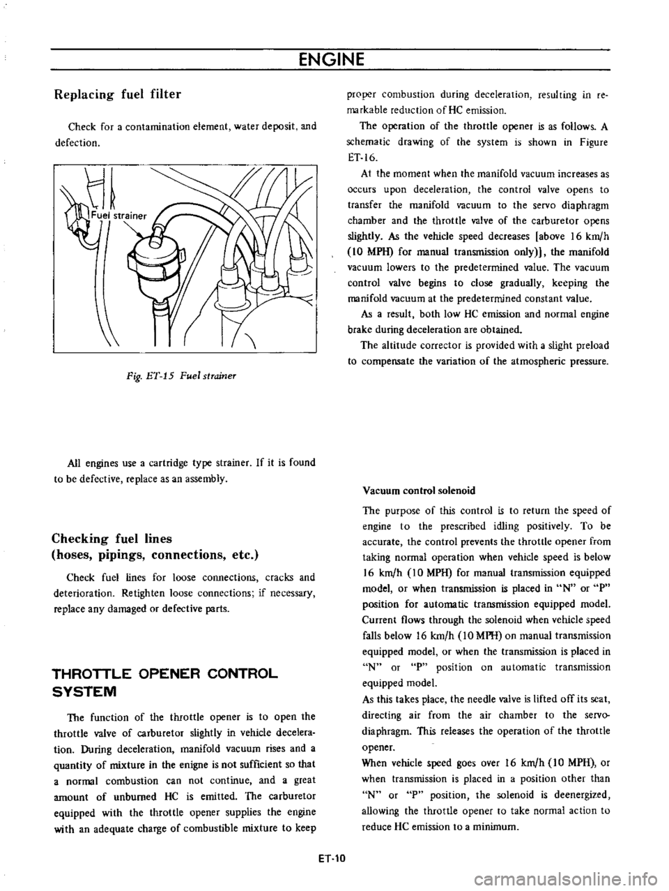
Replacing
fuel
filter
Check
for
a
contamination
element
water
deposit
and
defection
Fig
ET
15
Fuel
strcrineT
All
engines
use
a
cartridge
type
strainer
If
it
is
found
to
be
defective
replace
as
an
assembly
Checking
fuel
lines
hoses
pipings
connections
etc
Check
fuel
lines
for
loose
connections
cracks
and
deterioration
Retighten
loose
connections
if
necessary
replace
any
damaged
or
defective
parts
THROTTLE
OPENER
CONTROL
SYSTEM
The
function
of
the
throttle
opener
is
to
open
the
throttle
valve
of
carburetor
slightly
in
vehicle
decelera
tion
During
deceleration
manifold
vacuum
rises
and
a
quantity
of
mixture
in
the
enigne
is
not
sufficient
so
that
a
normal
combustion
can
not
continue
and
a
great
amount
of
unburned
HC
is
emitted
The
carburetor
equipped
with
the
throttle
opener
supplies
the
engine
with
an
adequate
charge
of
combustible
mixture
to
keep
proper
combustion
during
deceleration
resulting
in
re
markable
reduction
of
He
emission
The
operation
of
the
throttle
opener
is
as
follows
A
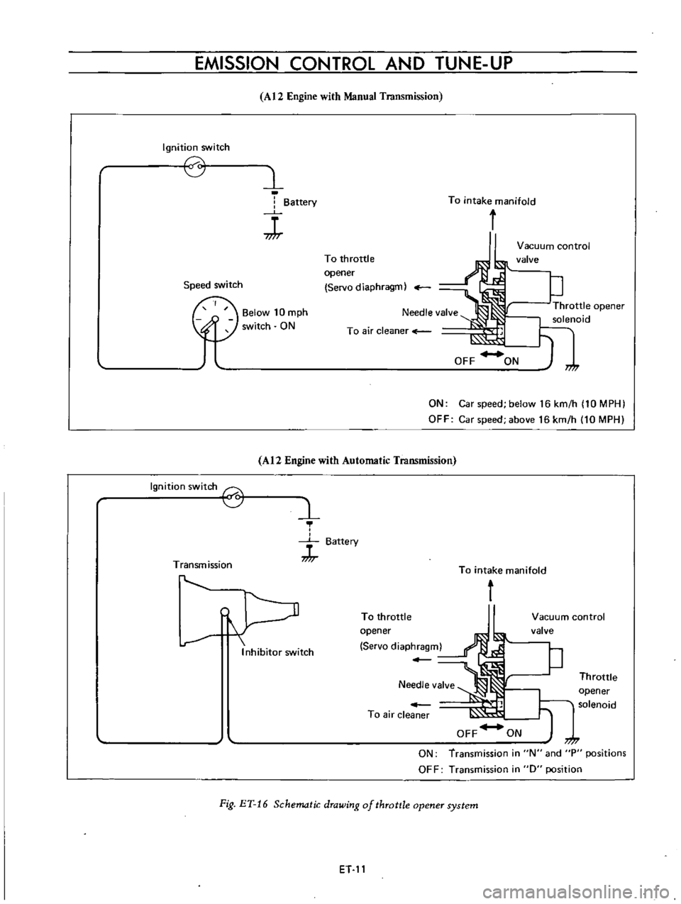
schematic
drawing
of
the
system
is
shown
in
Figure
ET
16
At
the
moment
when
the
manifold
vacuum
increases
as
occurs
upon
deceleration
the
control
valve
opens
to
transfer
the
manifold
vacuum
to
the
servo
diaphragm
chamber
and
the
throttle
valve
of
the
carburetor
opens
slightly
As
the
vehicle
speed
decreases
above
16
km
h
10
MPH
for
manual
transmission
only
the
manifold
vacuum
lowers
to
the
predetermined
value
The
vacuum
control
valve
begins
to
close
gradually
keeping
the
manifold
vacuum
at
the
predetermined
constant
value
As
a
result
both
low
HC
emission
and
normal
engine
brake
during
deceleration
are
obtained
The
altitude
corrector
is
provided
with
a
slight
preload
to
compensate
the
variation
of
the
atmospheric
pressure
Vacuum
control
solenoid
The
purpose
of
this
control
is
to
return
the
speed
of
engine
to
the
prescribed
idling
positively
To
be
accurate
the
control
prevents
the
throttle
opener
from
taking
normal
operation
when
vehicle
speed
is
below
16
km
h
IO
MPH
for
manual
transmission
equipped
model
or
when
transmission
is
placed
in
N
or
P
position
for
automatic
transmission
equipped
model
Current
flows
through
the
solenoid
when
vehicle
speed
falls
below
16
km
h
10
MPH
on
manual
transmission
equipped
model
or
when
the
transmission
is
placed
in
N
or
P
position
on
automatic
transmission
equipped
model
As
this
takes
place
the
needle
valve
is
lifted
off
its
seat
directing
air
from
the
air
chamber
to
the
servo
diaphragm
This
releases
the
operation
of
the
throttle
opener
When
vehicle
speed
goes
over
16
km
h
IO
MPH
or
when
transmission
is
placed
in
a
position
other
than
N
or
P
position
the
solenoid
is
deenergized
allowing
the
throttle
opener
to
take
normal
action
to
reduce
He
emission
to
a
minimum
ET
10
Page 316 of 513
EMISSION
CONTROL
AND
TUNE
UP
Ignition
switch
0
Speed
switch
Ignition
switch
6
Transmission
A12
Engine
with
Manual
Transmission
l
Battery
J
Below
10
mph
switch
ON
To
throttle
opener
Servo
diaphragm
Needle
valve
To
air
cleaner
To
intake
manifold
f
Vacuum
control
valve
p
Throttle
opener
noid
ON
Car
speed
below
16
km
h
10
MPH
OFF
Car
speed
above
16
km
h
10
MPH
A12
Engine
with
Automatic
Transmission
Inhibitor
switch
1
J
Battery
To
intake
manifold
t
ET
11
OFF
ON
Fig
BY
16
Schematic
drawing
of
throttle
opener
system
To
throttle
opener
Servo
diaphragm
Vacuum
control
valve
P
Throttle
t
opener
solenoid
7
7
ON
transmission
in
N
and
P
positions
OFF
Transmission
in
0
position