Page 72 of 513

PROPELLER
SHAFT
DIFFERENTIAL
CARRIER
The
gear
carrier
is
made
of
light
and
strong
aluminum
alloy
metal
and
hypoid
bevel
gear
is
used
Adjust
drive
pinion
bearing
preload
with
non
adjusting
type
spacer
and
pinion
height
and
side
bearing
adjust
ment
with
spacer
shim
s
Millimeter
standardization
stilI
remains
for
all
the
screw
threads
of
this
unit
Therefore
adjustment
figures
stamped
on
screws
adjusting
shims
washers
differential
case
drive
pinion
and
carrier
are
in
millimeters
in
accordance
with
the
millimeter
standardization
of
parts
The
proper
lubrication
to
the
gear
housing
is
necessary
otherwise
it
would
shorten
the
durability
of
the
gear
and
cause
other
troubles
The
lubricant
should
be
checked
each
5
000
km
3
000
miles
and
replenished
each
50
000
km
30
000
miles
The
lubricant
should
be
drained
and
ref11led
at
the
end
of
the
first
1
000
km
600
miles
to
eliminate
any
loose
material
from
the
sump
which
results
from
breaking
Differential
lubricant
should
be
changed
at
least
every
50
000
km
30
000
miles
ConsIderations
should
be
given
to
the
following
matters
I
Nominated
hypoid
gear
oil
must
be
used
2
It
is
prohibited
to
use
any
gear
oil
of
different
viscosity
The
same
brand
must
always
be
selected
3
The
standard
oil
capacity
is
about
0
75
liter
0
198
US
gal
REMOVAL
Fig
PD
5
Removing
differential
gear
carrier
To
remove
the
gear
carrier
assembly
disconnect
the
drive
pinion
companion
flange
te
flange
yoke
connection
and
remove
two
rear
axle
shafts
Refer
to
REAR
AXLE
for
the
work
DISASSEMBLY
I
Install
the
gear
carrier
assembly
on
the
Gear
Carrier
Attachment
ST06320000
ST06320000
Fig
PD
6
Holding
differential
camer
2
Inspect
the
following
before
disassembling
I
Inspect
the
tooth
contact
pattern
with
a
lead
oxide
2
Measure
backlash
between
drive
gear
and
pinion
gear
using
a
dial
indicator
3
Put
match
mark
on
one
side
of
the
side
bearing
cap
by
the
use
of
a
punch
SIDCBEMING
c
e
Fig
PD
7
Putting
mark
PD
5
Page 302 of 513
GENERAL
INFORMATION
RECOMMENDED
LUBRICANT
SPECI
FICATIONS
Item
Gasoline
engine
oil
o
Transmission
and
steering
Differential
Automatic
TIM
fluid
Multipurpose
grease
Brake
and
clutch
fluid
Antifreeze
coolant
i
Specifications
SAE
Classification
SO
or
SE
API
G
L
4
API
GL
5
Type
DEXRON
NLGI2
DOT
3
Long
Life
Coolant
GI
6
Remarks
Furthermore
refer
to
SAE
recommended
viscosity
table
See
Page
GI
5
Lithium
soap
base
Page 308 of 513

EMISSION
CONTROL
AND
TUNE
UP
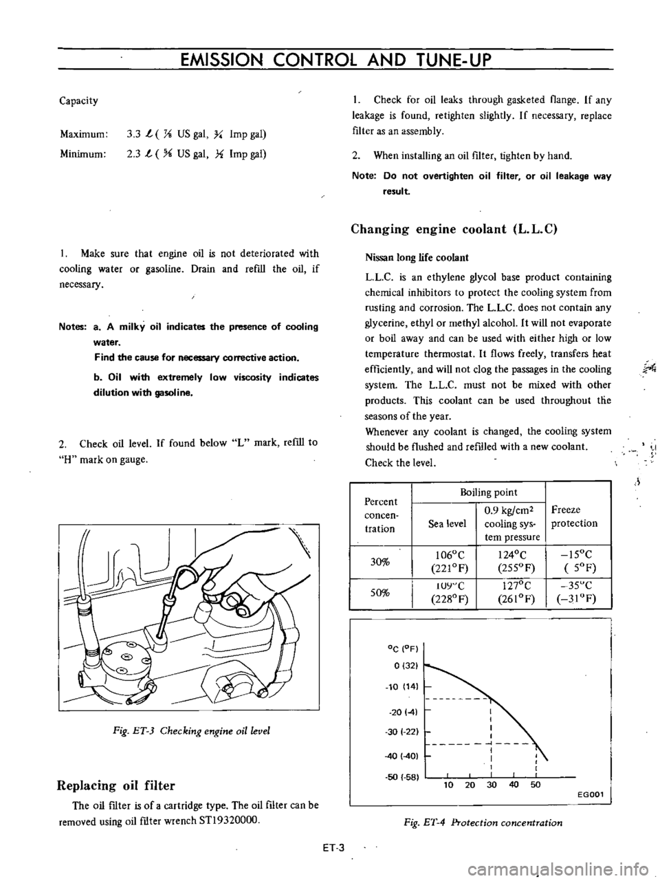
Capacity
Maximum
3
3
L
X
US
gal
y
Imp
gal
2
3
L
US
gal
f
Imp
gal
Minimum
Make
sure
that
engine
oil
is
not
deteriorated
with
cooling
water
or
gasoline
Drain
and
refill
the
oil
if
necessary
Notes
a
A
milky
oil
indicates
the
presence
of
cooling
water
Find
the
cause
for
necessary
corrective
action
b
Oil
with
extremely
low
viscosity
indicates
dilution
with
gasoline
2
Check
oil
level
If
found
below
L
mark
refill
to
H
mark
on
gauge
Fig
ET
3
Checking
engine
oil
level
Replacing
oil
filter
The
oil
ftIter
is
of
a
cartridge
type
The
oil
filter
can
be
removed
using
oil
ftIter
wrench
STl9320000
Check
for
oil
leaks
through
gasketed
flange
If
any
leakage
is
found
retighten
slightly
If
necessary
replace
filter
as
an
assembly
2
When
installing
an
oil
filter
tighten
by
hand
Note
Do
not
overtighten
oil
filter
or
oil
leakage
way
result
Changing
engine
coolant
L
L
C
Nissan
long
life
coolant
LLC
is
an
ethylene
glycol
base
product
containing
chemical
inhibitors
to
protect
the
cooling
system
from
rusting
and
corrosion
The
L
L
C
does
not
contain
any
glycerine
ethyl
or
methyl
alcohol
It
will
not
evaporate
or
boil
away
and
can
be
used
with
either
high
or
low
temperature
thermostat
It
flows
freely
transfers
heat
efficiently
and
will
not
clog
the
passages
in
the
cooling
system
The
LL
C
must
not
be
mixed
with
other
products
This
coolant
can
be
used
throughout
tlie
seasons
of
the
year
Whenever
any
coolant
is
changed
the
cooling
system
should
be
flushed
and
refilled
with
a
new
coolant
Check
the
level
J
Percent
Boiling
point
0
9
kgfcm2
Freeze
concen
tration
Sea
level
cooling
sys
protection
tern
pressure
30
1060
C
I
240C
15OC
221OF
255OF
5OF
50
IUY
C
1270C
35
C
2280
F
2610F
3IOF
DC
OF
0
321
10
14
20141
50
58
I
I
I
I
1
I
I
1
30
1
22
40
401
40
10
30
50
20
EGOOl
Fig
ET
4
Protection
concentration
ET
3
Page 333 of 513

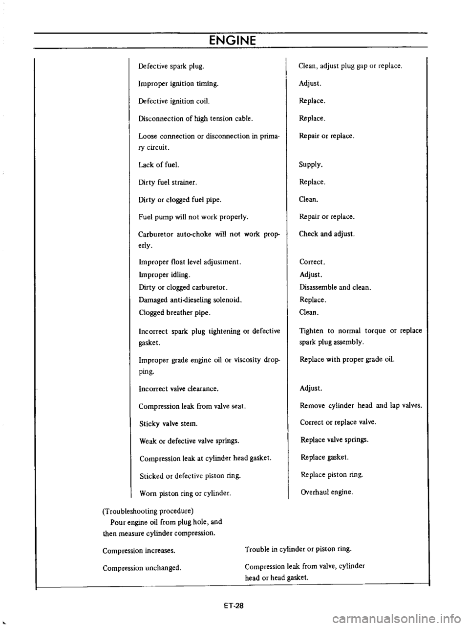
ENGINE
Defective
spark
plug
Improper
ignition
timing
Defective
ignition
coil
Disconnection
of
high
tension
cable
Loose
connection
or
disconnection
in
prima
ry
circuit
Lack
of
fuel
Dirty
fuel
strainer
Dirty
or
clogged
fuel
pipe
Fuel
pump
will
not
work
properly
Carburetor
auto
choke
will
not
work
prop
erly
Improper
float
level
adjustment
Improper
idling
Dirty
or
clogged
carburetor
Damaged
anti
dieseling
solenoid
Clogged
breather
pipe
Incorrect
spark
plug
tightening
or
defective
gasket
Improper
grade
engine
oil
or
viscosity
drop
ping
Incorrect
valve
clearance
Compression
leak
from
valve
seat
Sticky
valve
stem
Weak
or
defective
valve
springs
Compression
leak
at
cylinder
head
gasket
Sticked
or
defective
piston
ring
Worn
piston
ring
or
cylinder
Troubleshooting
procedure
Pour
engine
oil
from
plug
hole
and
then
measure
cylinder
compression
Clean
adjust
plug
gap
or
replace
Adjust
Replace
Replace
Repair
or
replace
Supply
Replace
Clean
Repair
or
replace
Check
and
adjust
Correct
Adjust
Disassemble
and
clean
Replace
Clean
Tighten
to
normal
torque
or
replace
spark
plug
assembly
Replace
with
proper
grade
oil
Adjust
Remove
cylinder
head
and
lap
valves
Correct
or
replace
valve
Replace
valve
springs
Replace
gasket
Replace
piston
ring
Overhaul
engine
Compression
increases
Trouble
in
cylinder
or
piston
ring
Compression
unchanged
Compression
leak
from
valve
cylinder
head
or
head
gasket
ET
28