1973 DATSUN B110 radiator cap
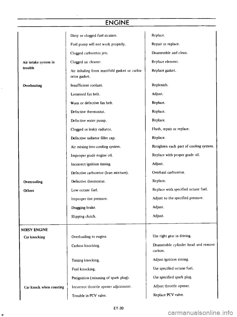
[x] Cancel search: radiator capPage 242 of 513

BODY
ELECTRICAL
Note
8
When
a
fuse
is
blown
off
be
sure
to
correct
the
cause
before
installing
new
fuse
b
Be
sure
to
use
fuse
having
the
rated
capacity
Do
not
use
fuse
having
larger
capacity
i
e
20A
JOA
etc
c
Particularly
when
the
fusible
link
is
fused
replace
with
a
designated
fusible
link
Green
color
link
for
model
8110
In
comparison
with
fuse
much
higher
current
flows
through
the
fusible
link
Moreover
it
is
important
to
eliminate
the
cause
of
blown
off
fusible
link
before
replacing
d
When
fuse
is
connected
incorrectly
and
the
contact
is
loose
voltage
drops
and
heat
are
gener
ated
resulting
abnormally
operated
electrical
equip
ment
Remove
dust
or
when
oxidized
polish
with
a
fine
emery
paper
so
that
the
contact
is
improved
LlGHTING
SYSTEM
CONTENTS
HEAD
LAMP
Descri
ption
Sealed
beam
replacement
Aiming
adjustment
FRONT
PARKING
AND
TURN
SIGNAL
SIDE
FLASHER
IMARKER
LAMP
AN
D
LICENSE
LAMP
REAR
COMBINATION
LAMPS
BULB
SPECIFICATIONS
TURN
SIGNAL
AND
DIMMER
COMBINATION
SWITCH
BE
7
BE
7
BE
7
BE
8
LAMP
BE
8
BE
9
BE10
BE10
HEAD
LAMP
Description
All
weather
type
sealed
beam
2
light
system
front
lamps
are
adopted
Each
lamp
of
both
side
head
lamps
is
provided
with
high
beam
filament
for
long
range
SOW
and
low
beam
filarnent
for
dipping
40W
In
other
words
the
lamp
is
of
a
double
filament
type
Sealed
beam
replacement
I
Rernove
the
wiring
socket
from
back
of
the
head
lamp
2
Remove
the
screws
attaching
the
front
grille
to
the
radiator
core
support
Coupe
only
Remove
three
retaining
screws
and
remove
the
head
lamp
rim
All
other
than
coupe
3
Loosen
three
screws
used
to
install
the
retaining
ring
on
the
sealed
bearn
mounting
ring
and
remove
the
sealed
Removal
LIGHTING
SWITCH
Removal
HAZARD
WARNING
SWITCH
PASSING
LIGHT
SWITCH
TROUBLE
DIAGNOSES
AND
CORRECTIONS
Head
lamp
Turn
signal
lamps
Tail
and
stop
lamp
license
lamp
back
up
lamp
BE
10
BE
11
BE
11
BE
11
BE
12
BE
12
BE
12
BE
13
BE
15
i
Ii
beam
unit
4
When
installing
a
new
unit
be
sure
to
position
the
Top
mark
to
the
top
of
ring
1
2
Sealed
beam
unit
Sealed
beam
mounting
ring
3
Retaining
ring
4
Aiming
adjusting
screws
Fig
BE
18
Replacing
sealed
beam
BE
7
Page 309 of 513

ENGINE
Checking
cooling
system
hoses
and
connections
Check
cooling
system
hoses
and
fiHings
for
loose
connections
and
deterioration
Retighten
or
replace
as
necessary
Inspection
of
radiator
cap
Apply
reference
pressure
0
9
kg
cm1
13
psi
to
radiator
cap
by
means
of
a
cap
tester
to
see
if
it
is
in
good
condition
Replace
cap
assembly
if
necessary
ET012
Fig
ET
5
Testing
radiator
cap
Cooling
system
pressure
test
With
radiator
cap
removed
apply
reference
pressure
1
6
kg
cm1
23
psi
to
the
cooling
system
bv
means
of
a
tester
to
check
for
leaks
at
the
system
compo
nents
Water
capacity
with
heater
4
9
l
I
Y
US
gal
l
i
Imp
gal
without
heater
4
2
l
I
i
US
gal
i
Imp
gal
Fig
ET
6
Testing
cooling
system
pressure
Checking
vaccum
fittings
hoses
and
connections
Check
vacuum
system
fittings
and
hoses
for
loose
connections
and
deterioration
Retighten
if
necessary
replace
any
deteriorated
parts
Checking
engine
compression
Compression
pressure
test
Note
To
test
cylinder
compression
remove
all
spark
plugs
and
hold
tester
fitting
tightly
in
spark
plug
hole
of
cylinder
The
tester
is
used
to
determine
whether
cylinder
can
hold
compression
or
whether
there
is
excessive
leakage
past
rings
etc
I
Td10
l
y
Fig
ET
7
Testing
compression
pressure
Test
compression
with
engine
warm
all
spark
plugs
removed
and
throttle
and
choke
valve
opened
No
cylinder
compression
should
be
less
than
80
of
highest
cylinder
s
Excessive
variation
between
cyl
inders
accompanied
by
low
speed
missing
of
the
cylinder
usually
indicates
a
valve
not
properly
seating
or
a
broken
piston
ring
Low
pressures
even
though
uniform
may
indicate
worn
rings
This
may
be
accompanied
by
excessive
oil
consumption
Test
conclusion
If
one
or
more
cylinders
read
low
inject
about
one
tablespoon
of
enigne
oil
on
top
of
the
pistons
in
low
ET
4
Page 335 of 513

Air
intake
system
in
trouble
Overheating
Overcooling
Others
NOISY
ENGINE
Car
knocking
Car
knock
when
coasting
ENGINE
Diny
ur
clogged
fuel
strainer
Fuel
pump
will
not
work
properly
Clogged
carburetor
jets
Clogged
air
cleaner
Air
inhaling
from
manifold
gasket
or
carbu
retor
gasket
Insufficient
coolant
Loosened
fan
belt
Worn
or
defective
fan
belt
Defective
thermostat
Defective
water
pump
Clogged
or
leaky
radiator
Defective
radiator
filler
cap
Air
mixing
into
cooling
system
Improper
grade
engine
oil
Incorrect
ignition
timing
Defective
carburetor
lean
mixture
Defective
thermostat
Low
octane
fuel
Improper
tire
pressure
Dragging
brake
Slipping
clutch
Overloading
to
engine
Carbon
knocking
Timing
knocking
Fuel
knocking
Preignition
misusing
of
spark
plug
Incorrect
throttle
opener
adjustment
Trouble
in
PCV
valve
ET
30
Replace
Repair
or
replace
Disassemble
and
clean
Replace
element
Replace
gasket
Replenish
Adjust
Replace
Replace
Replace
Flush
repair
or
replace
Replace
Retighten
each
part
of
cooling
system
Replace
with
proper
grade
oil
Adjust
Overhaul
carburetor
Replace
Replace
with
specified
octane
fuel
Adjust
to
the
specified
pressure
Adjust
Adjust
Use
right
gear
in
driving
Disassemble
cylinder
head
and
remove
carbon
Adjust
ignition
timing
Use
specified
octane
fuel
Use
specified
spark
plug
Adjust
throttle
opener
Replace
PCV
valve
Page 387 of 513

COOLING
SYSTEM
COOLING
SYSTEM
CONTENTS
DESCRIPTION
WATER
PUMP
Removal
THERMOSTAT
Removal
Inspection
CO
1
CO
2
CO
2
CO
2
CO
2
CO
2
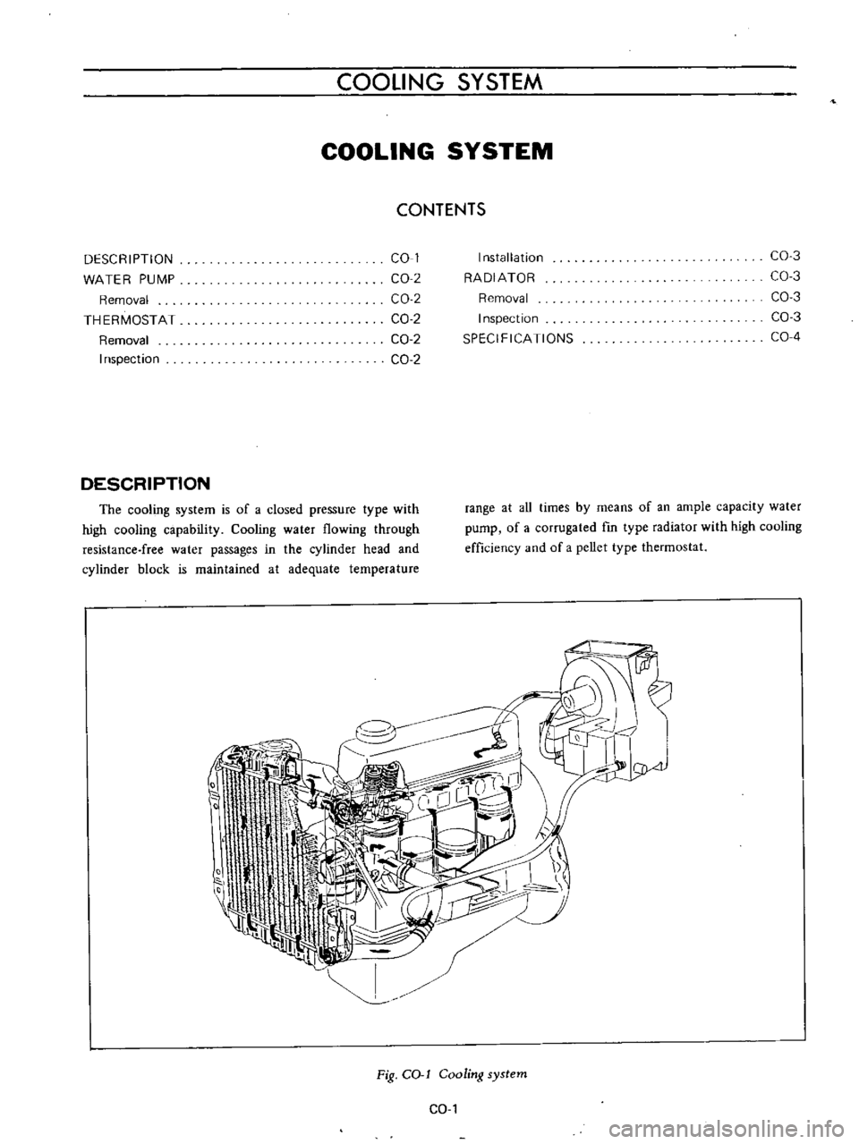
DESCRIPTION
The
cooling
system
is
of
a
closed
pressure
type
with
high
cooling
capability
Cooling
water
flowing
through
resistance
free
water
passages
in
the
cylinder
head
and
cylinder
block
is
maintained
at
adequate
temperature
Installation
RADIATOR
Removal
Inspection
SPECIFICATIONS
CO
3
CO
3
CO
3
CO
3
CO
4
range
at
aU
times
by
means
of
an
ample
capacity
water
pump
of
a
corrugated
fm
type
radiator
with
high
cooling
efficiency
and
of
a
pellet
type
thermostat
I
I
I
0
Jrl
oA
Fig
COol
Cooling
system
CO
I
Page 389 of 513

COOLING
SYSTEM
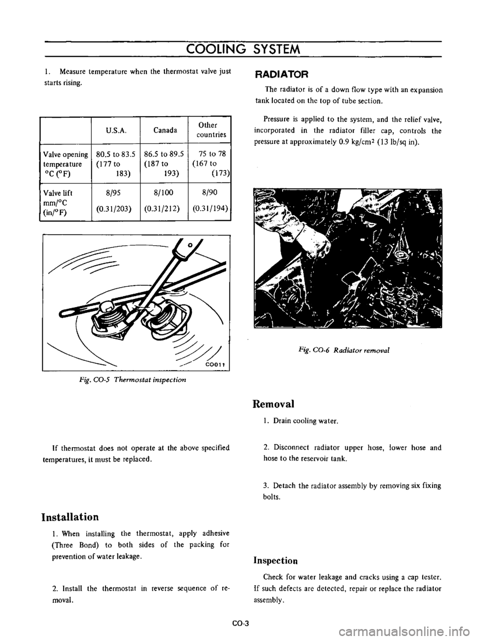
Measure
temperature
when
the
thermostat
valve
just
starts
rising
U
S
A
Canada
Other
countries
Valve
opening
80
5
to
83
5
86
5
to
89
5
75
to
78
temperature
l77
to
l87
to
167
to
OCeF
183
193
173
Valve
lift
8
95
8
100
8
90
mm
C
0
31
203
0
31
212
0
31
194
in
F
C0011
Fig
CQ
5
Thermostat
inspection
If
thermostat
does
not
operate
at
the
above
specified
temperatures
it
must
be
replaced
Installation
I
When
installing
the
thermostat
apply
adhesive
Three
Bond
to
both
sides
of
the
packing
for
prevention
of
water
leakage
2
Install
the
thermostat
in
reverse
sequence
of
re
moval
RADIATOR
The
radiator
is
of
a
down
flow
type
with
an
expansion
tank
located
on
the
top
of
tube
section
Pressure
is
applied
to
the
system
and
the
relief
valve
incorporated
in
the
radiator
filler
cap
controls
the
pressure
at
approximately
0
9
kg
cm2
l3
Ib
sq
in
Fig
CO
6
Radiator
removal
Removal
I
Drain
cooling
water
2
Disconnect
radiator
upper
hose
lower
hose
and
hose
to
the
reservoir
tank
3
Detach
the
radiator
assembly
by
removing
six
fixing
bolts
Inspection
Check
for
water
leakage
and
cracks
using
a
cap
tester
If
such
defects
are
detected
repair
or
replace
the
radiator
assembly
CO
3
Page 390 of 513

ENGINE
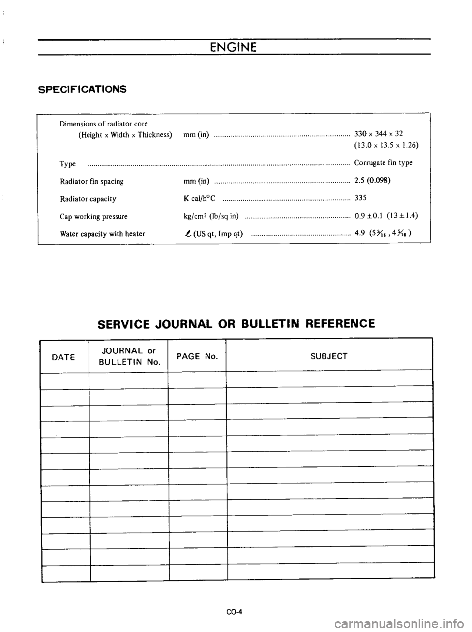
SPECIFICATIONS
Dimensions
of
radiator
core
Height
x
Width
x
Thickness
mm
in
330
x
344
x
32
13
0
x
13
5
x
1
26
Type
Corrugate
fin
type
Radiator
fin
spacing
mm
in
2
5
0
098
Radiator
capacity
K
cal
hoC
335
Water
capacity
with
heater
kg
em
lb
sq
in
t
US
qt
Imp
qt
0
9IO
l
13II4
4
9
5
I
4
X
Cap
working
pressure
SERVICE
JOURNAL
OR
BULLETIN
REFERENCE
DATE
JOURNAL
or
BULLETIN
No
PAGE
No
SUBJECT
CQ
4