1973 DATSUN B110 window
[x] Cancel search: windowPage 190 of 513

SERVI
oE
NuA
r
DATSUN
1200
MODEL
B
1
10
SERIES
I
NISSAN
I
NISSAN
MOTOR
CO
LTD
TOKYO
JAPAN
SECTION
BF
BODY
GENERAL
DESCRIPTION
UNDERBODY
ALIGNMENT
HOOD
FRONT
FENDER
AND
FRONT
END
TRUNK
LID
AND
REAR
BUMPER
DOORS
WINDSHIELD
AND
REAR
WINDOW
VENTILATOR
SEAT
INSTRUMENT
PANEL
ROOM
TRIM
BF
1
BF
9
BF
14
BF
17
BF
19
BF
24
BF
31
BF
37
BF38
BF
42
BF
43
Page 199 of 513
BODY
UNDERBODY
ALIGNMENT
CONTENTS
UNDERBODY
GENERAL
SERVICE
INFORMATION
ALIGNMENT
CHECKING
PROCEDURE
BF
9
BF
9
UNDERBODY
GENERAL
SERVICE
INFORMATION
Since
each
underbody
component
directly
affects
the
overall
strength
of
the
body
it
is
essential
that
proper
welding
sealing
and
rust
proofing
techniques
be
observed
during
service
operations
Whenever
the
body
is
repaired
be
sure
to
provide
the
repaired
body
parts
with
rust
proof
In
the
case
of
a
rust
proofmg
critical
underbody
component
it
is
essential
that
a
good
quality
type
air
dry
primer
such
as
corrosion
resistant
zinc
chromate
be
used
Do
not
use
combination
type
primer
surfacers
ALIGNMENT
CHECKING
PROCEDURE
Misalignment
in
the
underbody
affects
the
front
fender
door
trunk
lid
and
window
alignments
and
also
the
tail
gate
and
rear
body
opening
alignments
in
the
case
of
a
station
wagon
or
van
Underbody
misalignment
particularly
affects
the
suspension
system
thereby
causing
various
problems
that
arise
from
suspension
misalignment
It
is
essential
that
underbody
components
be
aligned
within
the
specified
dimensions
given
in
Figures
BF
13
14
and
IS
In
the
event
of
collision
damage
it
is
important
that
underbody
a1ignrnent
be
thoroughly
checked
and
if
necessary
realigned
to
the
specified
dirnensions
There
are
many
tools
that
may
be
ernployed
to
correct
collision
damage
such
as
frame
straightening
machines
external
pulling
equipment
other
standard
body
jacks
PRINCIPLES
OF
TRAMMING
CAR
PREPARATION
TRAMMING
SEQUENCE
BF
9
BF
10
BF
10
To
assist
in
checking
alignment
of
the
underbody
components
repairing
minor
underbody
damage
or
locating
replacement
parts
the
following
underbody
dimensions
and
alignment
checking
information
are
presented
PRINCIPLES
OF
TRAMMING
All
reference
locations
shown
in
Figure
BF
13
14
and
15
are
symmetrical
at
the
centerline
of
the
vehicle
For
example
wheo
performing
a
crosHheck
of
the
body
floor
panel
dimensions
Figures
BF
I3
14
and
IS
the
diagonal
measurement
should
be
the
same
in
boflii
directions
Cross
checking
operations
are
used
to
deter
mine
the
relationship
between
two
locations
on
the
underbody
To
measure
the
distance
between
any
two
reference
points
on
the
underbody
accurately
two
specifications
are
required
I
The
horizontal
dimension
between
the
two
points
to
be
measured
2
The
vertical
dimension
from
the
datum
line
to
the
points
to
be
measured
For
an
example
the
diagonal
measurement
calculated
on
a
horizontal
plane
between
reference
points
of
dimension
line
L
shown
in
Figure
BF
I3
is
631
3
mm
24
8
in
The
specifications
from
the
datum
line
have
a
vertical
height
difference
of
11
6
mm
0
456
in
between
the
forward
location
of
dimension
L
at
vertical
dimension
80
0
mm
3
150
in
and
the
rearward
location
of
dimension
L
at
vertical
dimension
91
6
mm
3
606
in
The
vertical
pointer
used
at
the
forward
location
should
be
positioned
so
as
to
extend
11
6
mm
0
456
in
further
from
the
tram
bar
than
the
BF
9
Page 214 of 513
BACK
DOOR
TORSION
BAR
BODY
A
D
Installation
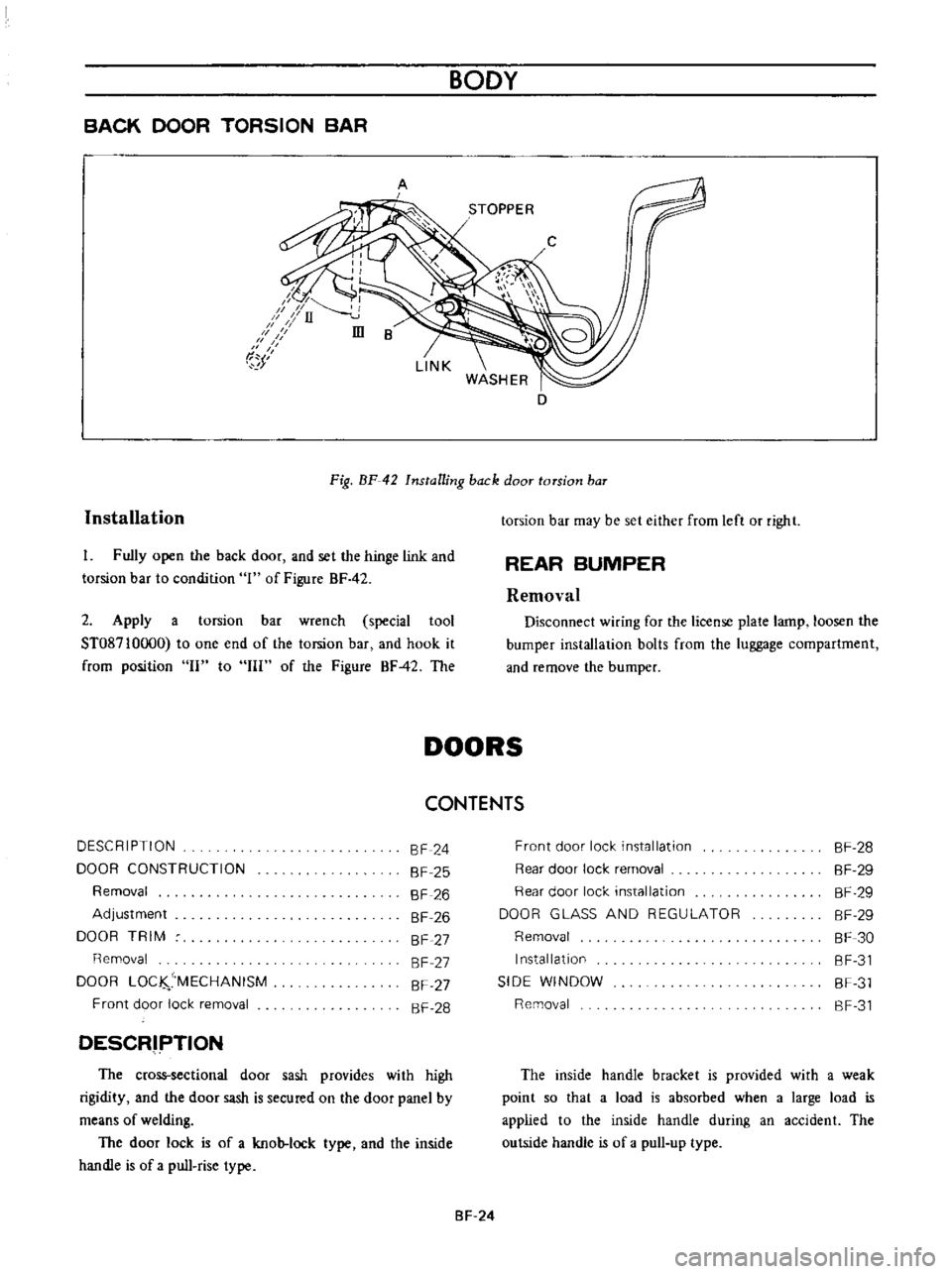
Fig
BF
42
Installing
back
door
torsion
baT
I
Fully
open
the
back
door
and
set
the
hinge
link
and
torsion
bar
to
condition
1
of
Figure
BF
42
2
Apply
a
torsion
bar
wrench
special
tool
ST08710oo0
to
one
end
of
the
torsion
bar
and
hook
it
from
position
II
to
III
of
the
Figure
BF42
The
torsion
bar
may
be
set
either
from
left
or
right
REAR
BUMPER
Removal
Disconnect
wiring
for
the
license
plate
lamp
loosen
the
bumper
installation
bolts
from
the
luggage
compartment
and
remove
the
bumper
DOORS
CONTENTS
DESCRIPTION
DOOR
CONSTRUCTION
Removal
Adjustment
DOOR
TRIM
Removal
DOOR
LOC
MECHANISM
Front
door
lock
removal
SF
24
SF
25
SF
26
SF
26
SF
27
SF
27
SF
27
SF
28
DESCRIPTION
The
cross
sectional
door
sash
provides
with
high
rigidity
and
the
door
sash
is
secured
on
the
door
panel
by
means
of
welding
The
door
lock
is
of
a
knob
lock
type
and
the
inside
handle
is
of
a
pull
rise
type
Front
door
lock
installation
Rear
door
lock
removal
Rear
door
lock
installation
DOOR
GLASS
AND
REGULATOR
Removal
Installation
SIDE
WINDOW
Removal
SF
28
SF
29
SF
29
SF
29
SF
30
SF
31
SF
31
SF
31
The
inside
handle
bracket
is
provided
with
a
weak
point
so
that
a
load
is
absorbed
when
a
large
load
is
applied
to
the
inside
handle
during
an
accident
The
outside
handle
is
of
a
pull
up
type
SF
24
Page 219 of 513
the
outside
handle
rod
@
is
provided
with
2
to
3
mm
0
0787
to
0
1181
in
play
in
the
stroke
If
the
nylon
nut
@
is
positioned
too
low
the
locking
plate
@
is
depressed
at
the
full
ratch
the
locking
plate
does
not
intermesh
with
the
ratchet
completely
and
the
knob
cannot
be
locked
If
play
in
stroke
of
the
outside
handle
rod
@
is
excessive
may
be
unlocked
up
to
5
mm
0
1967
in
stroke
of
the
outside
handle
will
be
insufficient
If
the
nylon
nut
is
loosened
the
above
described
trouble
occurs
Be
sure
to
secure
the
nut
completely
by
means
of
adhesive
Check
the
springs
@
and
@
for
rust
and
replace
as
required
Tightening
torque
Door
lock
installation
screw
0
12
to
0
2
kg
m
0
9
to
I
4
ft
lb
Door
lock
remote
control
installation
screw
0
12
to
0
2
kg
m
0
9
to
14
ft
lb
Outside
handle
installation
nut
0
2
to
0
3
kg
m
1
4
to
2
2
ft
Ib
Rear
door
lock
removal
1
Remove
the
parts
up
to
the
seal
screen
2
Raise
the
door
glass
to
the
top
and
remove
the
door
DOOR
GLASS
AND
REGULATOR
i
v
BODY
lock
knob
3
Remove
the
bell
crank
installation
screw
Hereinafter
the
instructions
for
removal
of
the
front
door
lock
apply
Fig
BF
54
Door
without
sealing
screen
Rear
door
lock
installation
Install
the
rear
door
lock
in
reverse
sequence
of
removal
Note
Except
for
the
precautions
for
outside
handle
the
precautions
for
the
front
door
lock
apply
AD
1
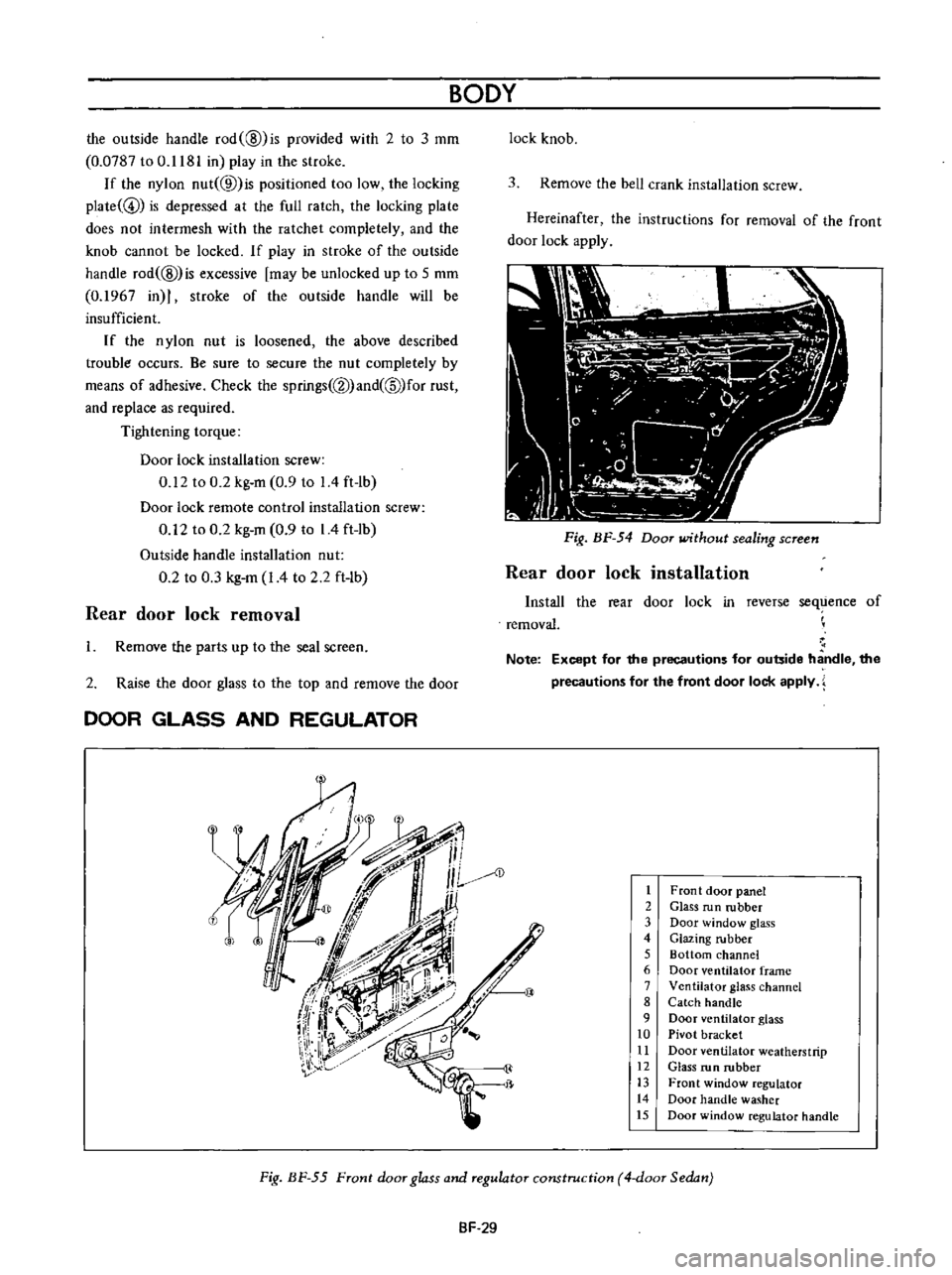
Front
door
panel
2
Glass
run
rubber
3
Door
window
glass
4
Glazing
rubber
5
Bottom
channel
6
Door
ventilator
frame
7
Ventilator
glass
channel
8
Catch
handle
9
Door
ventilator
glass
10
Pivot
bracket
11
Door
ventilator
weatherstrip
12
Glass
run
rubber
13
Front
window
regulator
14
Door
handle
washer
15
Door
window
regulator
handle
Fig
BF
55
Front
door
glass
and
regulator
construction
4
door
Sedan
SF
29
Page 220 of 513
BODY
i
1
Rear
door
panel
2
Glass
run
rubber
3
Partition
rear
door
weatherstrip
4
Rear
door
glass
5
Rear
door
corner
glass
6
Glazing
rubber
7
Bottom
channel
8
Door
window
regulator
9
Door
handle
washer
10
Door
window
regulator
handle
91
W
10
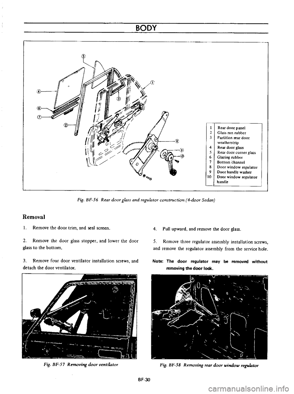
Fig
BF
56
Rear
door
glass
and
regulator
construction
4
door
Sedan
Removal
Remove
the
door
trim
and
seal
screen
2
Rernove
the
door
glass
stopper
and
lower
the
door
glass
to
the
bottorn
3
Remove
four
door
ventilator
installation
screws
and
detach
the
door
ventilator
Fig
BF
57
Removing
door
ventilator
4
Pull
upward
and
remove
the
door
glass
5
Remove
three
regulator
assembly
installation
screws
and
remove
the
regulator
assembly
from
the
service
hole
Note
The
door
regulator
may
be
removed
without
removing
the
door
lock
Fig
BF
58
Removing
rear
door
window
regulator
BF
30
Page 221 of 513

Installation
Install
the
door
glass
and
regulator
in
reverse
sequence
of
removal
Reinstall
the
seal
screen
after
correctly
adjusting
door
window
closing
SIDE
WINDOW
Removal
I
Remove
the
lock
pillar
moulding
and
remove
the
side
window
handle
set
screws
from
the
body
side
2
Loosen
the
side
window
hinge
installation
screws
and
remove
the
side
window
BODY
7
I
I
I
c
t
2
3
Side
window
glass
Side
window
hinge
Side
hinge
cover
4
Side
window
handle
5
Handle
shim
6
Catch
handle
bracket
Fig
BF
59
Side
window
construction
WINDSHIELD
AND
REAR
WINDOW
CONTENTS
REMOVAL
INSTAllATION
REAR
WINDOW
ELECTRIC
DEFROSTER
Option
SF
31
SF
32
SF
33
REMOVAL
1
Place
a
protective
cover
over
the
hood
front
fenders
instrument
panel
and
front
seat
2
Remove
rear
view
mirror
support
3
Remove
windshield
wiper
arm
assembly
4
On
inside
of
body
loosen
the
lip
of
the
rubber
channel
from
spot
welded
flange
along
the
top
and
sides
of
windshield
opening
With
the
palm
of
the
hand
apply
pressure
to
glass
near
edge
At
the
same
time
use
a
blunt
putty
knife
or
other
suitable
tool
and
carefully
assist
rubber
channel
over
spot
welded
flange
5
After
windshield
rubber
channel
is
free
from
spot
welded
flange
with
aid
of
helper
carefully
lift
windshield
assembly
frorn
body
opening
and
place
it
on
a
protected
bench
Removal
and
installation
Specifications
I
nspection
and
repair
WATERlEAK
CORRECTION
BF
34
SF
34
SF
34
SF
36
Fig
BF
60
Removing
windshield
Note
The
windshield
chrome
moulding
are
installed
in
the
rubber
channel
and
should
be
removed
prior
to
removing
rubber
channel
from
the
gla55
SF
31
Page 223 of 513
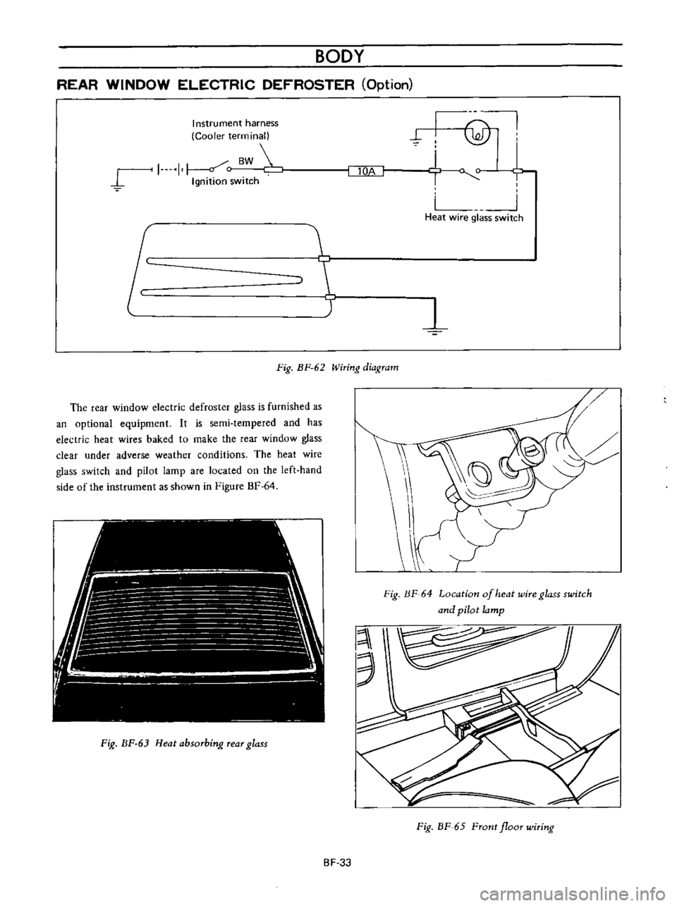
BODY
REAR
WINDOW
ELECTRIC
DEFROSTER
Option
J
Instrument
harness
Cooler
terminal
J
1
1
c
BW
Ignition
switch
I
lOA
@
hi
u
Heat
wire
glass
switch
T
Fig
BF
62
Wiring
diagram
The
rear
window
electric
defroster
glass
is
furnished
as
an
optional
equipment
It
is
semi
tempered
and
has
electric
heat
wires
baked
to
make
the
rear
window
glass
clear
under
adverse
weather
conditions
The
heat
wire
glass
switch
and
pilot
larnp
are
located
on
the
left
hand
side
of
the
instrument
as
shown
in
Figure
BF
64
Fig
BF
63
Heat
absorbing
rear
glass
Fig
HF
64
Location
of
heat
wire
glass
switch
and
pilot
lamp
3
Fig
BF
65
Front
floor
wiring
BF
33
Page 224 of 513
BODY
Removal
and
installation
The
rear
window
electric
defroster
glass
is
removed
from
or
installed
on
its
position
in
the
same
manner
as
that
for
the
standard
rear
window
glass
Heat
wire
harness
1
Fig
BF
66
Rear
floor
wiring
Note
a
Use
care
not
to
give
scratches
and
wiring
b
Remove
weather
strip
whenever
glass
is
to
be
replaced
After
glass
is
installed
in
place
apply
sealant
between
panel
and
weather
strip
1
Connection
Specifications
Glass
Semi
tempered
heat
absorbing
type
Power
consumption
75W
l2V
Heating
wire
Baked
on
rear
window
Interior
side
Heating
wire
coverage
Horizontal
Vertical
Full
width
390
mm
15
35
in
Inspection
and
repair
Ground
terminal
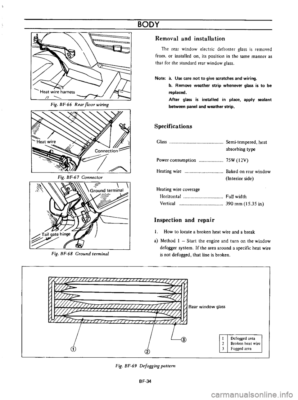
How
to
locate
a
broken
heat
wire
and
a
break
a
Method
I
Start
the
engine
and
turn
on
the
window
defogger
system
If
the
area
around
a
specific
heat
wire
is
not
defogged
that
line
is
broken
n
if
U
i
p
w
w
j
w
j
fj
f
i
j
L
1
2
Defogged
area
Broken
heat
wire
Fogged
area
Fig
BF
69
Defogging
pattern
BF
34