1973 DATSUN B110 high beam
[x] Cancel search: high beamPage 242 of 513

BODY
ELECTRICAL
Note
8
When
a
fuse
is
blown
off
be
sure
to
correct
the
cause
before
installing
new
fuse
b
Be
sure
to
use
fuse
having
the
rated
capacity
Do
not
use
fuse
having
larger
capacity
i
e
20A
JOA
etc
c
Particularly
when
the
fusible
link
is
fused
replace
with
a
designated
fusible
link
Green
color
link
for
model
8110
In
comparison
with
fuse
much
higher
current
flows
through
the
fusible
link
Moreover
it
is
important
to
eliminate
the
cause
of
blown
off
fusible
link
before
replacing
d
When
fuse
is
connected
incorrectly
and
the
contact
is
loose
voltage
drops
and
heat
are
gener
ated
resulting
abnormally
operated
electrical
equip
ment
Remove
dust
or
when
oxidized
polish
with
a
fine
emery
paper
so
that
the
contact
is
improved
LlGHTING
SYSTEM
CONTENTS
HEAD
LAMP
Descri
ption
Sealed
beam
replacement
Aiming
adjustment
FRONT
PARKING
AND
TURN
SIGNAL
SIDE
FLASHER
IMARKER
LAMP
AN
D
LICENSE
LAMP
REAR
COMBINATION
LAMPS
BULB
SPECIFICATIONS
TURN
SIGNAL
AND
DIMMER
COMBINATION
SWITCH
BE
7
BE
7
BE
7
BE
8
LAMP
BE
8
BE
9
BE10
BE10
HEAD
LAMP
Description
All
weather
type
sealed
beam
2
light
system
front
lamps
are
adopted
Each
lamp
of
both
side
head
lamps
is
provided
with
high
beam
filament
for
long
range
SOW
and
low
beam
filarnent
for
dipping
40W
In
other
words
the
lamp
is
of
a
double
filament
type
Sealed
beam
replacement
I
Rernove
the
wiring
socket
from
back
of
the
head
lamp
2
Remove
the
screws
attaching
the
front
grille
to
the
radiator
core
support
Coupe
only
Remove
three
retaining
screws
and
remove
the
head
lamp
rim
All
other
than
coupe
3
Loosen
three
screws
used
to
install
the
retaining
ring
on
the
sealed
bearn
mounting
ring
and
remove
the
sealed
Removal
LIGHTING
SWITCH
Removal
HAZARD
WARNING
SWITCH
PASSING
LIGHT
SWITCH
TROUBLE
DIAGNOSES
AND
CORRECTIONS
Head
lamp
Turn
signal
lamps
Tail
and
stop
lamp
license
lamp
back
up
lamp
BE
10
BE
11
BE
11
BE
11
BE
12
BE
12
BE
12
BE
13
BE
15
i
Ii
beam
unit
4
When
installing
a
new
unit
be
sure
to
position
the
Top
mark
to
the
top
of
ring
1
2
Sealed
beam
unit
Sealed
beam
mounting
ring
3
Retaining
ring
4
Aiming
adjusting
screws
Fig
BE
18
Replacing
sealed
beam
BE
7
Page 243 of 513

n
YR
f
f1
JC
1
r
8bD
l
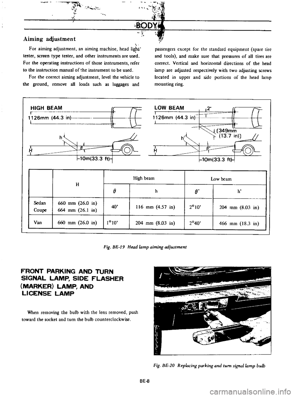
Aiming
adjustment
For
aiming
adjustment
an
aiming
machine
head
i
l
tester
screen
type
tester
and
other
instruments
are
used
For
the
operating
instructions
of
those
instruments
refer
to
the
instruction
manual
of
the
instrument
to
be
used
For
the
correct
airning
adjustment
level
the
vehicle
to
the
ground
remove
all
loads
such
as
luggages
and
HIGH
BEAM
I
1126mm
44
3
in
I
it
E
U
o
h
H
I
10m
33
3
ft
1
r
passengers
except
for
the
standard
equipment
spare
tire
and
tools
and
make
sure
that
pressures
of
all
tires
are
correct
Vertical
and
horizontal
directions
of
the
head
lamp
are
adjusted
respectively
with
two
adjusting
screws
located
in
upper
and
side
portions
of
the
head
lamp
mounting
ring
lOW
BEAM
12
I
f
tt
1126mm
44
3
in
I
l
349mm
h
t
13
7
in
10m
33
3
ft
I
H
I
High
beam
Low
beam
H
j
h
j
h
Sedan
660
mm
26
0
in
2010
Coupe
664
mm
26
1
in
40
116
mm
4
57
in
204
mm
8
03
in
Van
660
mm
26
0
in
1010
204
mm
8
03
in
2040
466
mm
18
3
in
Fig
BE
19
Head
lamp
aiming
adjustment
FRONT
PARKING
AND
TURN
SIGNAL
LAMP
SIDE
FLASHER
MARKER
LAMP
AND
LICENSE
LAMP
When
removing
the
bulb
with
the
lens
removed
push
toward
the
socket
and
turn
the
bulb
counterclockwise
Fig
BE
20
Replacing
parking
and
turn
signa
lamp
bulb
BE
8
Page 247 of 513

BODY
PASSING
LIGHT
SWITCH
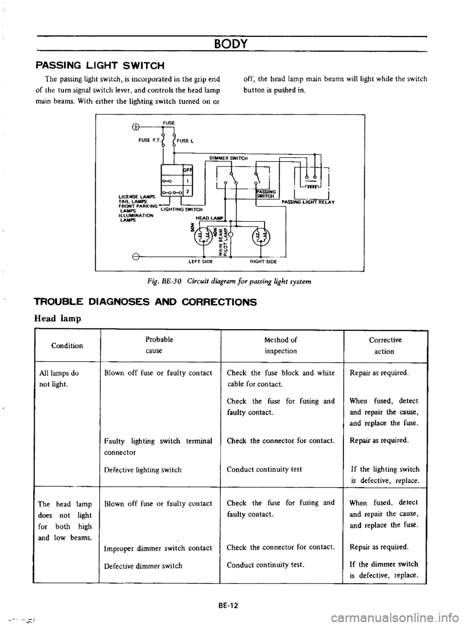
The
passing
light
switch
is
incorporated
in
the
grip
end
of
the
turn
signal
switch
lever
and
controls
the
head
lamp
main
beams
With
either
the
lighting
switch
turned
on
or
off
the
head
lamp
main
beams
will
light
while
the
switch
button
is
pushed
in
CB
FUSE
FUSE
P
T
FUSE
L
DI
TCH
ti
r
1
I
Y
fflf
0
00
0
2
ASSIHG
LICENSE
LAMPS
SWITCH
L
TAil
lAMPS
1
I
I
PASSING
LIGHT
RELAY
FRONT
PARKING
LAMPS
LIGHTING
SWITCH
1
NATlON
HEAD
lAMP
nt
OF
LEFT
sIDe
RIGtfT
SIDE
Fig
BE
30
Circuit
diagram
for
passing
light
system
TROUBLE
DIAGNOSES
AND
CORRECTIONS
Head
lamp
Probable
Me
thod
of
Condition
inspection
cause
All
lamps
do
not
light
Blown
off
fuse
or
faulty
contact
Check
the
fuse
block
and
white
cable
for
contact
Check
the
fuse
for
fusing
and
faulty
contact
Faulty
lighting
switch
terminal
connector
Check
the
connector
for
contact
Defective
lighting
switch
Conduct
continuity
test
The
head
lamp
Blown
off
fuse
or
faulty
contact
does
not
light
for
both
high
and
low
beams
Check
the
fuse
for
fusing
and
faulty
contact
Improper
dimmer
switch
contact
Check
the
connector
for
contact
Defective
dimmer
switch
Conduct
continuity
test
BE
12
r
Corrective
action
Repair
as
required
When
fused
detect
and
repair
the
cause
and
replace
the
fuse
Repair
as
required
If
the
ligh
ting
swi
tch
is
defective
replace
When
fused
detect
and
repair
the
cause
and
replace
the
fuse
Repair
as
required
I
f
the
dimmer
switch
is
defective
replace
Page 248 of 513

BODY
ELECTRICAL
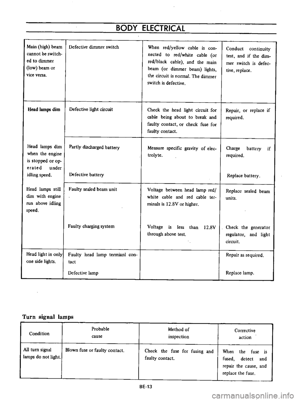
Main
high
beam
Defective
dimmer
switch
cannot
be
switch
ed
to
dimmer
low
beam
or
vice
versa
Head
lamps
dim
Defective
light
circuit
Head
lamps
dim
Partly
discharged
battery
when
the
engine
is
stopped
or
op
era
ted
under
idling
speed
Defective
battery
Head
lamps
still
Faulty
sealed
beam
unit
dim
with
engine
run
above
idling
speed
Faulty
charging
system
Head
light
in
only
one
side
lights
Faulty
head
lamp
terrnianl
con
tact
Defective
lamp
Turn
signal
lamps
Probable
Condition
cause
All
turn
signal
Blown
fuse
or
faulty
contact
lamps
do
not
light
When
red
yellow
cable
is
con
nected
to
red
white
cable
or
red
black
cable
and
the
main
beam
or
dimmer
beam
lights
the
circuit
is
nonnal
The
dimmer
switch
is
defective
Check
the
head
light
circuit
for
cable
being
about
to
break
and
faulty
contact
or
check
fuse
for
faulty
contact
Measure
specific
gravity
of
elec
trolyte
Voltage
between
head
lamp
red
white
cable
and
red
cable
ter
minals
is
12
8V
or
higher
Voltage
is
less
than
12
8V
through
above
test
Method
of
inspection
Check
the
fuse
for
fusing
and
faulty
contact
BE
13
Conduct
continuity
test
and
if
the
dirn
mer
switch
is
defec
tive
replace
Repair
or
replace
if
required
Charge
battery
if
required
Replace
battery
Replace
sealed
beam
units
Check
the
generator
regulator
and
light
circuit
Repair
as
required
Replace
lamp
Corrective
action
When
the
fuse
is
fused
detect
and
repair
the
cause
and
replace
the
fuse
Page 256 of 513

BODY
ElECTRICAL
When
the
ignition
switch
is
set
to
ON
the
ignition
wa
rning
circuit
is
closed
and
current
flows
flows
from
the
ignition
switch
to
the
warning
lamp
bulb
and
ground
through
the
regulator
When
the
engine
is
started
and
the
generator
comes
into
operation
the
generator
output
current
opposes
the
current
flowing
from
the
warning
lamp
in
effect
it
breaks
the
warning
circuit
ground
connection
and
the
lamp
goes
out
l
r
hffi
u
z
Ignition
switch
I
Q
6
I
0
c
M
1
E
8
ca
i
L
g
PI
lot
c
P
I
j
co
rt
0
relay
E
0
5
y
y
1
N
N
3
Alternator
Regulator
Fig
BE
41
Circuit
of
ignition
warning
system
HAND
BRAKE
WARNING
LAMP
This
lamp
functions
both
hand
brake
warning
larnp
and
BULB
SPECIFICATIONS
service
brake
line
pressure
differential
warning
lamp
When
a
difference
between
front
and
rear
brake
line
pressures
reaches
the
rated
range
13
to
17
kgfcm2
185
to
242
lb
sq
in
the
ground
circuit
for
the
warning
lamp
is
closed
and
the
warning
lamp
lights
IGNITION
SWITCH
WARNING
LAMP
L
E
WARNING
SWITCH
1
SERVICE
BRAKE
LINE
PRESSU
R
E
DIFFERENTIAL
WARNING
J
SWITCH
Fig
BE
42
Circuit
diagram
for
brake
warning
system
tern
Specifications
Square
type
meter
Round
type
meter
Meter
illumination
larnp
VoW
12
3
4
2
12
1
7
3
Turn
signal
pilot
lamp
VoW
12
3
4
2
12
1
7
2
Head
lamp
main
high
beam
VoW
12
3
4
I
12
17
1
pilot
lamp
Ignition
warning
lamp
VoW
123
4
I
12
17
1
Oil
pressure
warning
lamp
VoW
12
3
4
1
12
1
7
1
Hand
brake
warning
lamp
VoW
12
1
7
1
for
U
S
A
CANADA
Clock
illumination
lamp
VoW
123
4
I
12
17
2
Figure
encircled
in
parentheses
indicates
number
of
bulbs
used
BE
21