Page 225 of 513

BODY
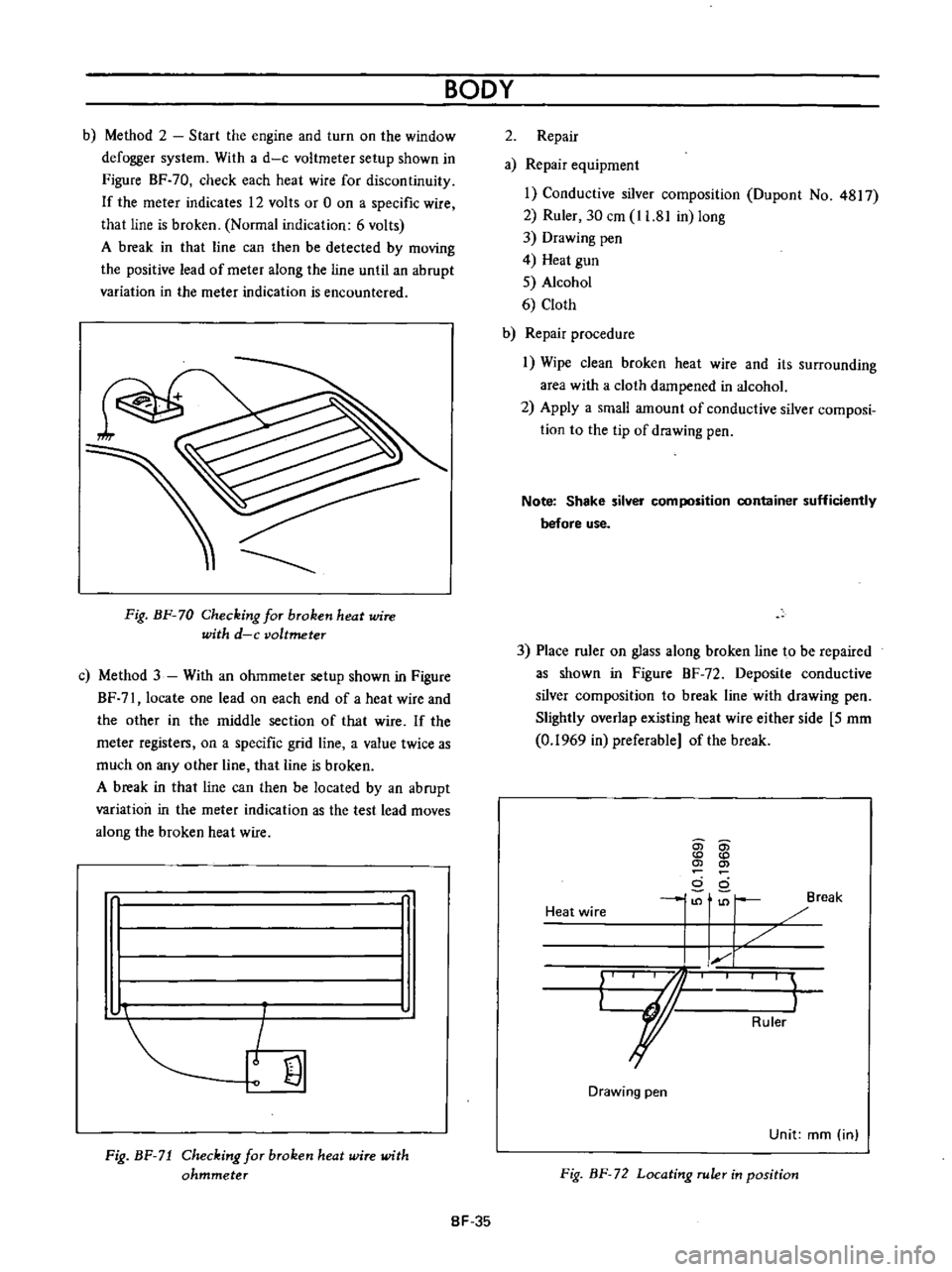
b
Method
2
Start
the
engine
and
turn
on
the
window
defogger
system
With
a
d
c
voltmeter
setup
shown
in
Figure
BF
70
check
each
heat
wire
for
discontinuity
If
the
meter
indicates
12
volts
or
0
on
a
specific
wire
that
line
is
broken
Normal
indication
6
volts
A
break
in
that
line
can
then
be
detected
by
moving
the
positive
lead
of
meter
along
the
line
until
an
abrupt
variation
in
the
meter
indication
is
encountered
Fig
BF
70
Checking
for
broken
heat
wire
with
d
c
voltmeter
c
Method
3
With
an
ohmmeter
setup
shown
in
Figure
BF
7l
locate
one
lead
on
each
end
of
a
heat
wire
and
the
other
in
the
rniddle
section
of
that
wire
If
the
meter
registers
on
a
specific
grid
line
a
value
twice
as
much
on
any
other
line
that
line
is
broken
A
break
in
that
line
can
then
be
located
by
an
abrupt
variation
in
the
meter
indication
as
the
test
lead
moves
along
the
broken
heat
wire
r
I
I
I
J
I
I
v
Ejl
Fig
BF
71
Checking
for
broken
heat
wire
with
ohmmeter
2
Repair
a
Repair
equipment
1
Conductive
silver
composition
Dupont
No
4817
2
Ruler
30
em
11
81
in
long
3
Drawing
pen
4
Heat
gun
5
Alcohol
6
Cloth
b
Repair
procedure
1
Wipe
clean
broken
heat
wire
and
its
surrounding
area
with
a
cloth
dampened
in
alcohol
2
Apply
a
small
amount
of
conductive
silver
composi
tion
to
the
tip
of
drawing
pen
Note
Shake
silver
composition
container
sufficiently
before
use
3
Place
ruler
on
glass
along
broken
line
to
be
repaired
as
shown
in
Figure
BF
72
Deposite
conductive
silver
composition
to
break
line
with
drawing
pen
Slightly
overlap
existing
heat
wire
either
side
5
mm
0
1969
in
preferable
of
the
break
Heat
wire
0
en
0
0
d
ci
1
I
Break
I
1
I
kr
I
I
Ruler
Drawing
pen
Unit
mm
in
Fig
BF
72
Locating
ruler
in
position
8F
35
Page 226 of 513

Drawing
pen
ri
Rear
window
L
Ii
r
Heat
wire
2
Silver
Imposition
3
Ruler
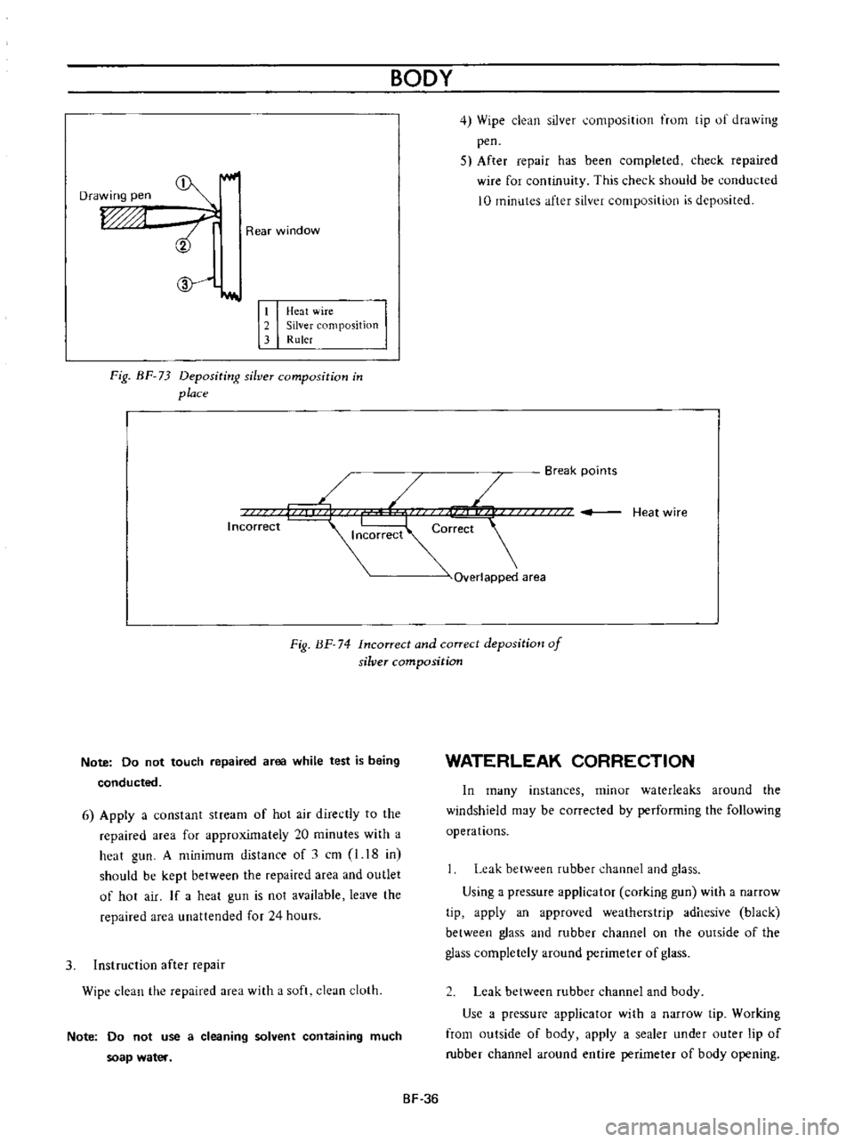
Fig
BF
73
Depositi
rg
silver
composition
in
place
BODY
4
Wipe
clean
silver
umposition
trom
tip
of
drawing
pen
5
After
repair
has
been
completed
check
repaired
wire
for
continuity
This
check
shuuld
be
conducted
10
minutes
after
silver
composition
is
deposited
Break
points
L
Heat
wire
orrect
r
Overlapped
area
Incorrect
Fig
BF
74
Incorrect
and
correct
deposition
of
silver
composition
Note
Do
not
touch
repaired
area
while
test
is
being
conducted
6
Apply
a
constant
stream
of
hot
air
directly
to
the
repaired
area
for
approximately
20
minutes
with
a
heat
gun
A
minimum
distance
of
1
cm
l
18
in
should
be
kept
between
the
repaired
area
and
outlet
of
hot
air
If
a
heat
gun
is
not
available
leave
the
repaired
area
unattended
for
24
hours
3
Instruction
after
repair
Wipe
clean
the
repaired
area
with
a
soft
clean
cloth
Note
Do
not
use
a
cleaning
solvent
containing
much
soap
water
WATERLEAK
CORRECTION
In
many
instances
minor
waterleaks
around
the
windshield
may
be
corrected
by
performing
the
following
operations
Leak
between
rubber
channel
and
glass
Using
a
pressure
applicator
corking
gun
with
a
narrow
tip
apply
an
approved
weatherstrip
adhesive
black
between
glass
and
rubber
channel
on
the
outside
of
the
glass
completely
around
perimeter
of
glass
Leak
between
rubber
channel
and
body
Use
a
pressure
applicator
with
a
narrow
tip
Working
from
outside
of
body
apply
a
sealer
under
outer
lip
of
rubber
channel
around
entire
perimeter
of
body
opening
SF
36
Page 227 of 513
BODY
VENTILATOR
CONTENTS
DESCRIPTION
BF
37
DESCRIPTION
In
this
body
ventilation
system
air
is
taken
from
the
air
intake
on
the
cowl
top
and
ventilator
on
the
front
door
and
exhausted
from
the
slip
shape
air
outlets
on
the
4
1
4
door
sedan
I
Coupe
COWL
TOP
GRILLE
BF
38
rear
pillar
body
side
for
coupe
and
side
window
Thus
the
passenger
compartment
is
ventilated
sufficiently
L
2
door
sedan
I
I
1
Station
wagon
or
Van
Fig
BF
75
Ventilation
system
BF
37
Page 228 of 513

@
c
@
CD
w
1
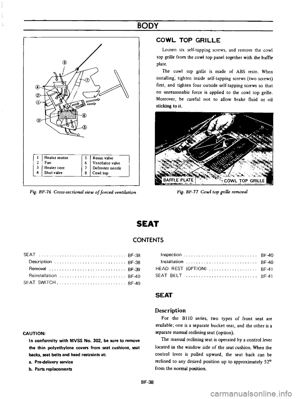
Heater
motor
2
Fan
3
Heater
core
4
Shut
valve
5
Room
valve
6
Ventilator
valve
7
Defroster
nozzle
8
Cowl
top
Fig
BF
76
Cross
sectional
view
of
forced
ventilation
BODY
COWL
TOP
GRILLE
Loosen
six
self
tapping
screws
and
remove
the
cowl
top
grille
from
the
cowl
top
panel
together
with
the
baffle
plate
The
cowl
top
grille
is
made
of
ABS
resin
When
installing
tighten
inside
self
tapping
screws
two
screws
first
and
lighten
four
outside
self
tapping
screws
so
that
no
unreasonable
force
is
applied
to
the
cowl
top
grille
Moreover
be
careful
not
to
allow
brake
fluid
or
oil
sticking
to
it
Fig
BF
77
Cowl
top
grille
removal
SEAT
CONTENTS
SEAT
Description
Removal
Reinstallation
SEAT
SWI
TCH
BF
38
BF
38
BF
39
BF
40
BF
40
CAUTION
I
n
conformity
with
MVSS
No
302
be
sure
to
remove
the
thin
polyethylene
covers
from
seat
cushions
seat
backs
seat
belts
and
head
restraints
at
a
Pi
Helivery
service
b
Parts
replacements
Inspection
Installation
HEAD
REST
OPTIONI
SEAT
BELT
BF
40
BF
40
BF
41
BF
41
SEAT
Description
For
the
BHO
series
two
types
of
front
seat
are
available
one
is
a
separate
bucket
seat
and
the
other
is
a
separate
manual
reclining
seat
option
The
manual
reclining
seat
is
operated
by
a
control
lever
located
in
the
window
side
of
the
seat
cushion
When
the
control
lever
is
pulled
upward
the
seat
back
can
be
reclined
to
any
desired
position
up
to
approximately
520
from
the
normal
position
BF
38