1973 DATSUN B110 wiring
[x] Cancel search: wiringPage 54 of 513

through
all
drive
positions
and
place
the
lever
in
park
P
position
In
this
inspection
the
car
must
be
placed
on
a
level
surface
The
amount
of
the
oil
varies
with
the
temperature
As
a
rule
the
oil
level
must
be
measured
after
its
tempera
ture
becomes
sufficiently
high
I
Fill
the
oil
to
the
line
H
The
difference
of
capacities
between
both
H
and
L
is
approximately
0
4
liter
7
8
U
S
pt
3
4
Imper
pt
and
therefore
take
care
not
to
fill
beyond
the
line
H
2
At
the
time
of
the
above
topping
up
and
changing
of
oil
care
should
be
taken
of
to
prevent
mixing
the
oil
with
dust
and
water
2
Inspecting
oil
condition
The
condition
of
oil
sticking
to
the
level
gauge
indicates
whether
to
over
haul
and
repair
the
transmission
or
look
for
the
defective
part
If
the
oil
has
deteriorated
into
a
varnish
like
quality
it
causes
the
con
trol
valve
to
stick
The
blackened
oil
gives
the
proof
of
the
burned
clutch
brake
band
etc
In
these
cases
the
transmission
must
be
replaced
Notes
a
In
oil
level
checking
use
special
paper
waste
to
handle
the
level
gauge
and
take
care
not
to
let
the
scraps
of
paper
and
cloth
tick
to
the
gauge
b
Insert
the
gauge
fully
and
take
it
out
quickly
before
splashing
oil
adheres
to
the
gauge
and
theu
observe
the
level
c
Use
automatic
transmission
fluid
having
DEXRON
iden
tIficatIon
only
in
the
3N71
B
automatic
transmission
d
Pay
atteutIon
because
the
oil
to
be
used
dIffers
from
that
i
used
in
the
Nissan
Full
Automatic
Transmission
3N7IA
Never
mix
the
oil
with
that
CHASSIS
Inspection
and
repair
of
oil
leakage
When
oil
leakage
takes
place
the
portion
near
the
leakage
is
covered
with
oil
presenting
difficulty
in
de
tecting
the
spot
Therefore
the
places
where
oil
seals
and
gaskets
are
equipped
are
enumerated
below
I
Converter
housing
The
rubber
ring
of
oil
pump
hous
ing
The
oil
eaI
of
oil
pump
housing
The
oil
seal
of
engine
crankshaft
The
bolts
of
converter
housing
to
case
2
Transmission
and
rear
extension
Junction
of
transmission
and
rear
extension
Oil
tube
connectors
Oil
pan
Oil
pressure
inspection
holes
Refer
to
Figure
AT
112
The
mounting
portion
of
vacuum
diaphragm
and
downshift
solenoid
Breather
and
oil
charging
pipe
Speedometer
pinion
sleeve
The
oil
seal
of
rear
extension
To
exactly
locate
the
place
of
oil
leakage
proceeds
as
follows
Place
the
vehicle
in
a
pit
and
by
sampling
the
leaked
oil
examine
whe
ther
it
is
the
torq
le
converter
oil
or
not
The
torque
converter
oil
assumes
color
like
red
wine
when
shipped
from
the
factory
so
it
is
ea
ily
distin
guished
from
engine
oil
or
gear
oil
Cleanly
wipe
off
the
leaking
oil
and
dust
and
detect
the
spot
of
oil
leakage
Use
nonflammable
organic
solvent
such
as
carbon
tetrachloride
for
wip
ing
Raise
the
oil
temperature
by
op
erating
the
engine
and
shift
the
lever
to
0
to
heighten
the
oil
pressure
The
spot
of
oil
leakage
will
then
be
found
more
easily
Note
A
the
oil
leakage
from
the
breather
does
not
take
place
except
when
running
at
high
speed
it
is
impossible
to
locate
the
spot
of
leakage
with
vehicle
stalled
AT
50
Checking
engine
idling
rprn
The
engine
idling
revolution
should
be
properly
adjusted
If
the
engine
revolution
is
too
low
the
engine
does
not
operate
smoothly
and
if
too
high
a
strong
shock
or
creep
develops
when
changing
over
from
N
to
D
or
R
Specified
idling
speed
650
rpm
at
D
position
800
rpm
at
N
position
Checking
and
adjusting
kick
down
switch
and
downshift
solenoid
When
the
kick
down
operation
is
not
made
properly
or
the
speed
chang
ing
point
is
too
high
check
the
kick
down
switch
downshift
solenoid
and
wiring
between
them
When
the
igni
tion
key
is
positioned
at
the
1st
stage
and
the
accelerator
pedal
is
depressed
deeply
the
switch
contact
should
be
closed
and
the
solenoid
should
click
If
it
does
not
click
it
indicates
a
defect
Then
check
each
part
with
the
testing
instruments
See
Figure
AT
I09
0
0
1
M
r
7
I
Y
ATl08
Fig
A
T
l
09
Downshift
solenoid
Note
Watch
for
oil
leakage
from
transmission
case
Page 58 of 513
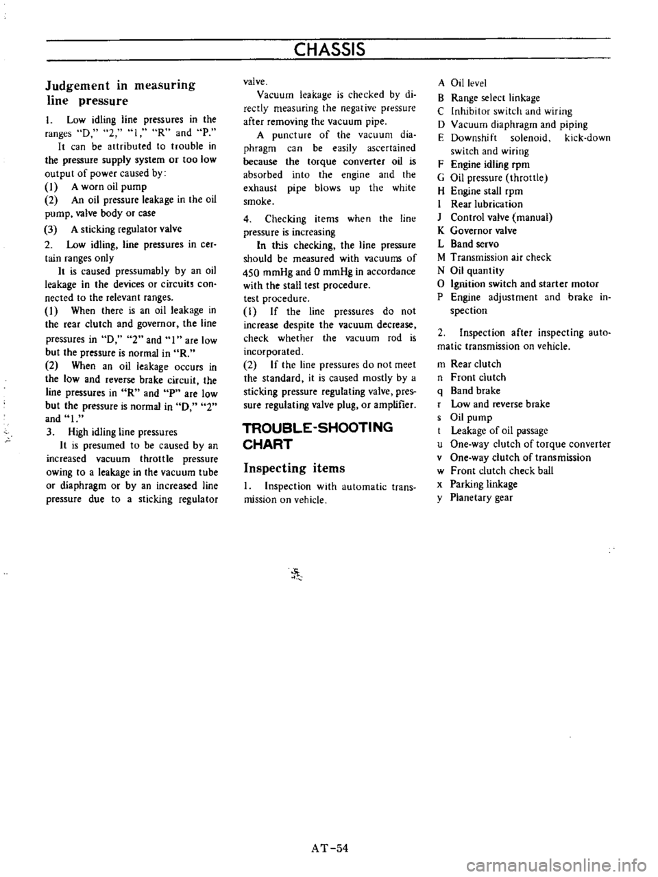
Judgement
in
measurmg
line
pressure
I
Low
idling
line
pressures
in
the
ranges
D
2
loR
and
P
It
can
be
artributed
to
trouble
in
the
pressure
supply
system
or
too
low
output
of
power
caused
by
1
A
worn
oil
pump
2
An
oil
pressure
leakage
in
the
oil
pump
valve
body
or
case
3
A
sticking
regulator
valve
2
Low
idling
line
pressures
in
cer
tain
ranges
only
It
is
caused
pressumabIy
by
an
oil
leakage
in
the
devices
or
circuits
con
nected
to
the
relevant
ranges
1
When
there
is
an
oil
leakage
in
the
rear
clutch
and
governor
the
line
pressures
in
D
2
and
I
are
low
but
the
pressure
is
normal
in
R
2
When
an
oil
leakage
occurs
in
the
low
and
reverse
brake
circuit
the
line
pressures
in
R
and
p
are
low
but
the
pressure
is
normal
in
0
2
and
I
3
High
idling
line
pressures
It
is
presumed
to
be
caused
by
an
increased
vacuum
throttle
pressure
owing
to
a
leakage
in
the
vacuum
tube
or
diaphragm
or
by
an
increased
line
pressure
due
to
a
sticking
regulator
CHASSIS
valve
Vacuum
leakage
is
checked
by
di
reetly
measuring
the
negative
pressure
after
removing
the
vacuum
pipe
A
puncture
of
the
vacuum
dia
phragm
can
be
easily
ascertained
because
the
torque
converter
oil
is
absorbed
into
the
engine
and
the
exhaust
pipe
blows
up
the
white
smoke
4
Checking
items
when
the
line
pressure
is
increasing
In
trJs
checking
the
line
pressure
should
be
measured
with
vacuums
of
450
mmHg
and
0
mmHg
in
accordance
with
the
stall
test
procedure
test
procedure
1
If
the
line
pressures
do
not
increase
despite
the
vacuum
decrease
check
whether
the
vacuum
rod
is
incorporated
2
If
the
line
pressures
do
not
meet
the
standard
it
is
caused
mostly
by
a
sticking
pressure
regulating
valve
pres
sure
regulating
valve
plug
or
amptifier
TROUBLE
SHOOTING
CHART
Inspecting
items
1
Inspection
with
automatic
trans
mission
on
vehicle
J
AT
54
A
Oil
level
B
Range
selecr
linkage
C
Inhibitor
switch
and
wiring
D
Vacuum
diaphragm
and
piping
E
Downshift
solenoid
kick
down
switch
and
wiring
F
Engine
idling
rpm
G
Oil
pressure
throttle
H
Engine
stall
rpm
I
Rear
lubrication
J
Control
valve
manual
K
Governor
valve
L
Band
servo
M
Transmission
air
check
N
Oil
quantity
o
Ignition
switch
and
starter
motor
P
Engine
adjustment
and
brake
in
spection
2
Inspection
after
inspecting
auto
matic
transmission
on
vehicle
m
Rear
clutch
n
Front
clutch
q
Band
brake
r
Low
and
reverse
brake
s
Oil
pump
Leakage
of
oil
passage
u
One
way
clutch
of
torque
converter
v
One
way
clutch
of
transmission
w
Front
clutch
check
ball
x
Parking
linkage
y
Planetary
gear
Page 207 of 513

BODY
FRONT
FENDER
AND
FRONT
END
CONTENTS
FRONT
FENDER
Removal
FRONT
BUMPER
BF
17
BF
17
BF
18
FRONT
FENDER
i
RADIATOR
GRILLE
OUTSIDE
MIRROR
BF
18
BF18
1
Front
fender
2
Cowl
top
sealer
3
Front
fender
sealer
4
Cowl
top
5
Side
dash
board
6
Front
pillar
7
Front
bumper
8
Front
bumper
stay
9
Front
bumper
side
bracket
10
Bumper
side
bracket
shim
Removal
Fig
BF
27
Front
fender
and
front
end
components
I
Open
the
hood
disconnect
the
battery
terrninal
for
the
sake
of
safety
and
disconnect
wirings
for
the
head
lamp
and
side
marker
lamp
at
their
connecting
terminals
2
Remove
the
front
bumper
radiator
grille
and
radiator
grille
surround
3
Remove
the
sm
moulding
and
holding
the
fender
remove
it
Fig
BF
28
Removing
front
fender
I
BF
17
Page 214 of 513
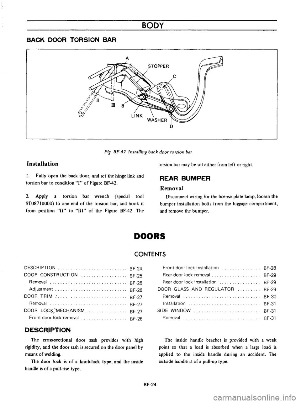
BACK
DOOR
TORSION
BAR
BODY
A
D
Installation
Fig
BF
42
Installing
back
door
torsion
baT
I
Fully
open
the
back
door
and
set
the
hinge
link
and
torsion
bar
to
condition
1
of
Figure
BF
42
2
Apply
a
torsion
bar
wrench
special
tool
ST08710oo0
to
one
end
of
the
torsion
bar
and
hook
it
from
position
II
to
III
of
the
Figure
BF42
The
torsion
bar
may
be
set
either
from
left
or
right
REAR
BUMPER
Removal
Disconnect
wiring
for
the
license
plate
lamp
loosen
the
bumper
installation
bolts
from
the
luggage
compartment
and
remove
the
bumper
DOORS
CONTENTS
DESCRIPTION
DOOR
CONSTRUCTION
Removal
Adjustment
DOOR
TRIM
Removal
DOOR
LOC
MECHANISM
Front
door
lock
removal
SF
24
SF
25
SF
26
SF
26
SF
27
SF
27
SF
27
SF
28
DESCRIPTION
The
cross
sectional
door
sash
provides
with
high
rigidity
and
the
door
sash
is
secured
on
the
door
panel
by
means
of
welding
The
door
lock
is
of
a
knob
lock
type
and
the
inside
handle
is
of
a
pull
rise
type
Front
door
lock
installation
Rear
door
lock
removal
Rear
door
lock
installation
DOOR
GLASS
AND
REGULATOR
Removal
Installation
SIDE
WINDOW
Removal
SF
28
SF
29
SF
29
SF
29
SF
30
SF
31
SF
31
SF
31
The
inside
handle
bracket
is
provided
with
a
weak
point
so
that
a
load
is
absorbed
when
a
large
load
is
applied
to
the
inside
handle
during
an
accident
The
outside
handle
is
of
a
pull
up
type
SF
24
Page 223 of 513
BODY
REAR
WINDOW
ELECTRIC
DEFROSTER
Option
J
Instrument
harness
Cooler
terminal
J
1
1
c
BW
Ignition
switch
I
lOA
@
hi
u
Heat
wire
glass
switch
T
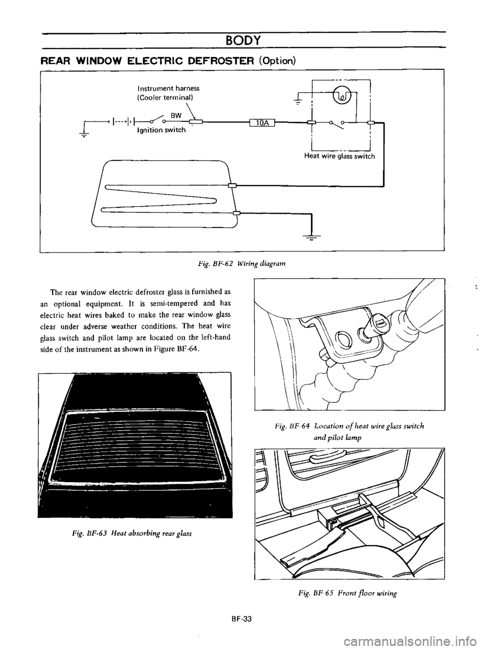
Fig
BF
62
Wiring
diagram
The
rear
window
electric
defroster
glass
is
furnished
as
an
optional
equipment
It
is
semi
tempered
and
has
electric
heat
wires
baked
to
make
the
rear
window
glass
clear
under
adverse
weather
conditions
The
heat
wire
glass
switch
and
pilot
larnp
are
located
on
the
left
hand
side
of
the
instrument
as
shown
in
Figure
BF
64
Fig
BF
63
Heat
absorbing
rear
glass
Fig
HF
64
Location
of
heat
wire
glass
switch
and
pilot
lamp
3
Fig
BF
65
Front
floor
wiring
BF
33
Page 224 of 513
BODY
Removal
and
installation
The
rear
window
electric
defroster
glass
is
removed
from
or
installed
on
its
position
in
the
same
manner
as
that
for
the
standard
rear
window
glass
Heat
wire
harness
1
Fig
BF
66
Rear
floor
wiring
Note
a
Use
care
not
to
give
scratches
and
wiring
b
Remove
weather
strip
whenever
glass
is
to
be
replaced
After
glass
is
installed
in
place
apply
sealant
between
panel
and
weather
strip
1
Connection
Specifications
Glass
Semi
tempered
heat
absorbing
type
Power
consumption
75W
l2V
Heating
wire
Baked
on
rear
window
Interior
side
Heating
wire
coverage
Horizontal
Vertical
Full
width
390
mm
15
35
in
Inspection
and
repair
Ground
terminal
How
to
locate
a
broken
heat
wire
and
a
break
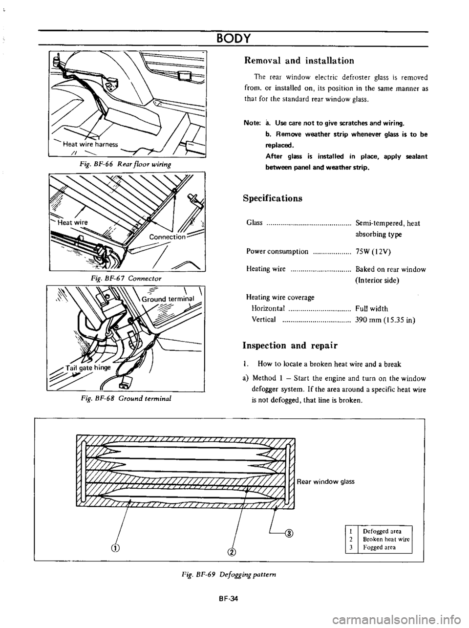
a
Method
I
Start
the
engine
and
turn
on
the
window
defogger
system
If
the
area
around
a
specific
heat
wire
is
not
defogged
that
line
is
broken
n
if
U
i
p
w
w
j
w
j
fj
f
i
j
L
1
2
Defogged
area
Broken
heat
wire
Fogged
area
Fig
BF
69
Defogging
pattern
BF
34
Page 232 of 513

BODY
INSTRUMENT
PANEL
CONTENTS
REMOVAL
BF
42
REMOVAL
Fig
BF
88
Removing
instrument
panel
Note
There
are
two
types
of
instrument
panel
square
type
and
round
type
However
both
of
them
are
removed
and
reinstalled
in
the
same
manner
Disconnect
the
battery
cable
at
the
battery
terminal
2
Disconnect
the
wiring
harness
connector
units
Disconnect
the
instrument
harness
from
the
engine
compartment
harness
Disconnect
the
instrument
harness
from
the
turn
signal
switch
Disconnect
the
instrument
harness
frorn
the
body
harness
Disconnect
the
instrumen
t
harness
connected
to
the
door
switch
stop
lamp
switch
flasher
unit
and
passing
light
relay
option
REINSTALLATION
BF
43
Note
When
disconnecting
the
wiring
harness
recom
mend
to
use
tags
for
identifying
their
relationship
3
Disconnect
cables
for
radio
antenna
and
speaker
4
Remove
the
package
tray
the
shell
cover
and
turn
signal
switch
Note
Work
may
be
carried
out
without
removing
die
steering
wheel
However
it
is
recommended
to
remove
the
steering
wheel
50
that
work
can
be
carried
out
more
easily
5
Disconnect
the
speedometer
cable
from
the
speedometer
unit
6
Disconnect
the
heater
control
cable
at
the
heater
side
Fig
BF
89
Removing
imtrument
panel
Ii
BF
42
Page 235 of 513
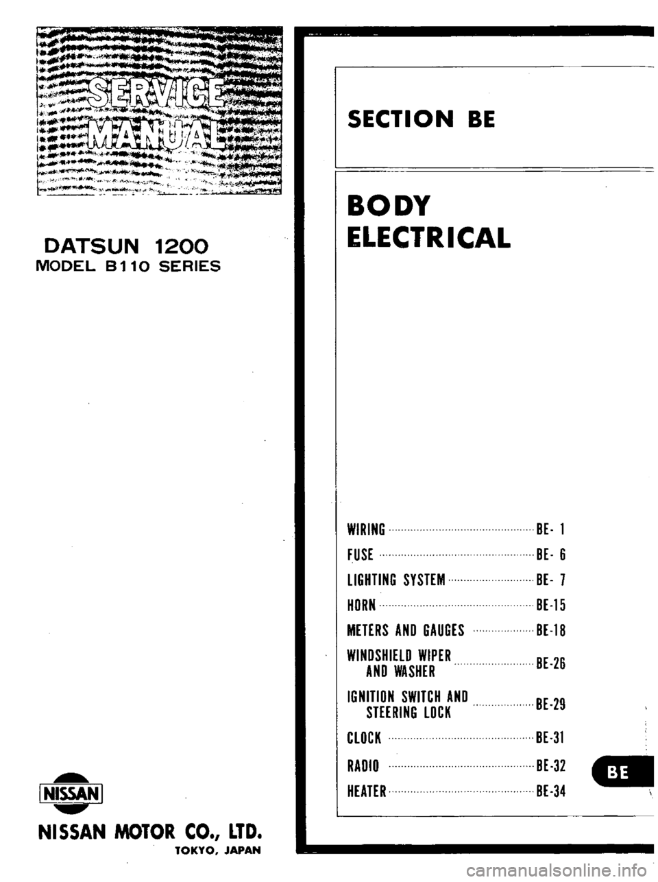
DATSUN
1200
MODEL
B
11
0
SERIES
I
NISSAN
I
NISSAN
MOTOR
CO
LTD
TOKYO
JAPAN
SECTION
BE
BODY
ELECTRICAL
WIRING
FUSE
LIGHTING
SYSTEM
HORN
METERS
AND
GAUGES
WINDSHIELD
WIPER
AND
WASHER
IGNITION
SWITCH
AND
STEERING
LOCK
CLOCK
RADIO
HEATER
BE
1
BE
6
BE
7
BE
15
BE
18
BE
26
BE
29
BE
31
BE
32
BE
34