1973 DATSUN B110 wiring
[x] Cancel search: wiringPage 236 of 513

BODY
ELECTRICAL
WIRING
CONTENTS
WIRING
HARNESS
Engine
compartment
harness
I
nstrument
harness
BE
1
BE
1
BE
2
WIRING
HARNESS
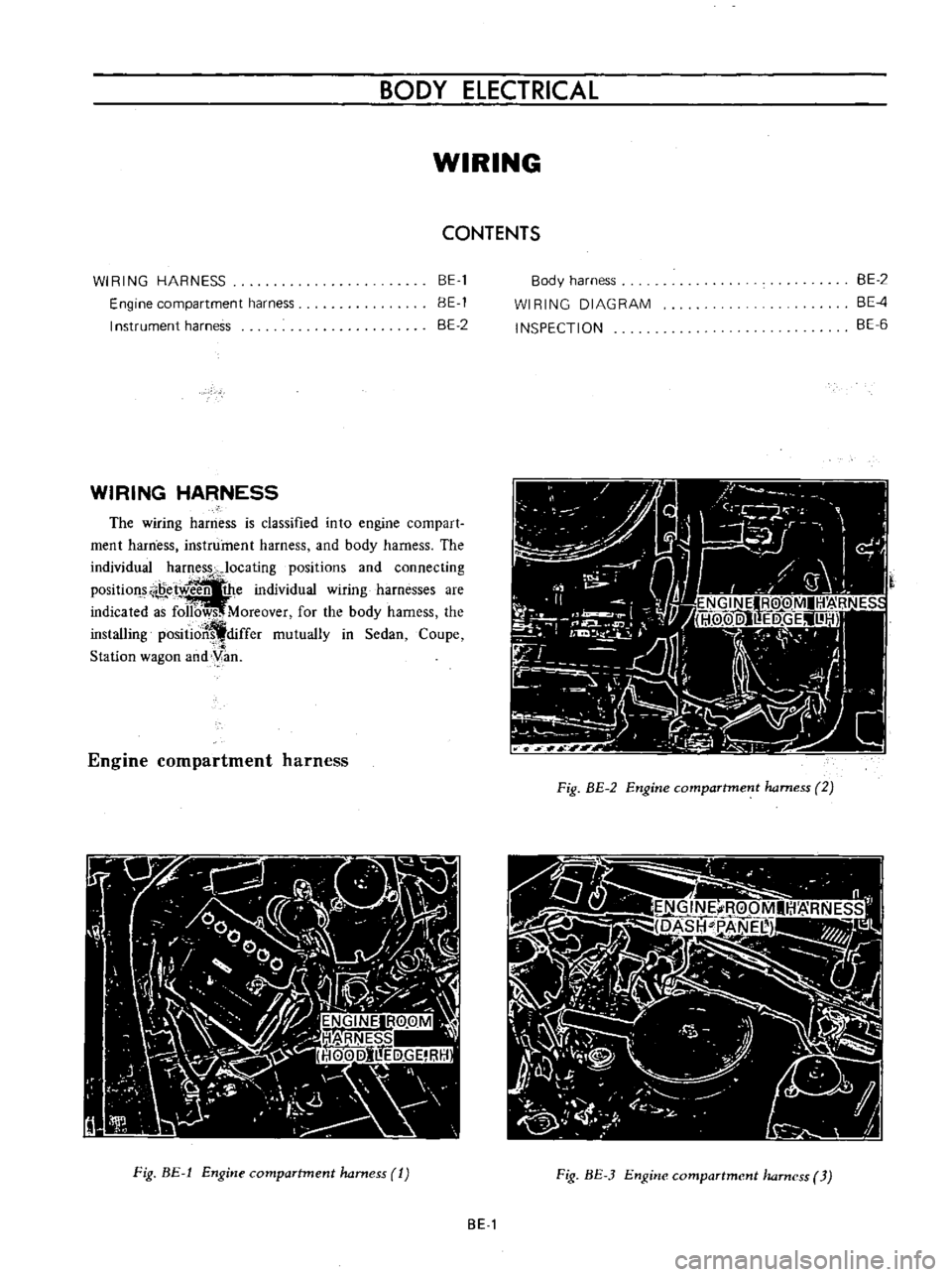
The
wiring
harness
is
classified
into
engine
compart
ment
harness
instrument
harness
and
body
harness
The
individual
harness
Jocating
positions
and
connecting
Position
e
w
the
individual
wiring
harnesses
are
indicated
a
f
Moreover
for
the
body
harness
the
installing
positioJ
differ
mutually
in
Sedan
Coupe
Station
wagon
and
yan
Engine
compartment
harness
Fig
BE
1
Engine
compartment
harness
1
Body
harness
WI
RING
DIAGRAM
INSPECTION
BE
2
BE
4
BE
6
A
0
Ij
7
9
Fig
BE
2
Engine
compartment
harness
2
Fig
BE
3
Engine
compartment
harness
3
BE
1
Page 237 of 513

Instrument
harness
Harnessterminal
in
the
engine
compartment
Switch
and
control
connecting
unit
Fig
BE4
Instrument
harness
I
I
Instrument
harness
2
Engine
room
harness
I
3
Body
harness
Fi
BE
5
Wiring
harness
connections
Body
harness
Fi
R
B1
6
Hocly
hamcss
1
BODY
Fig
BE
7
Body
harness
2
r
lj
I
I
I
I
Body
harness
2
Combination
lamp
RH
131
Body
earth
Fig
BE
8
Body
harness
Sednn
l
j
J
2
it
I
lJt
l
I
I
Body
harness
2
Combination
lamp
LH
7
13
I
To
Ikense
bmp
Fig
BE
9
Body
harness
Sedan
8E
2
Page 239 of 513

SOD
I
HlRlNG
OlAGRAM
j
1
i
Il
fI
J
i
i
g
Cl
r
t
0
tf
j
i
r
U
i
q
l
1
v
t
f3
J
J
o
o
0
J
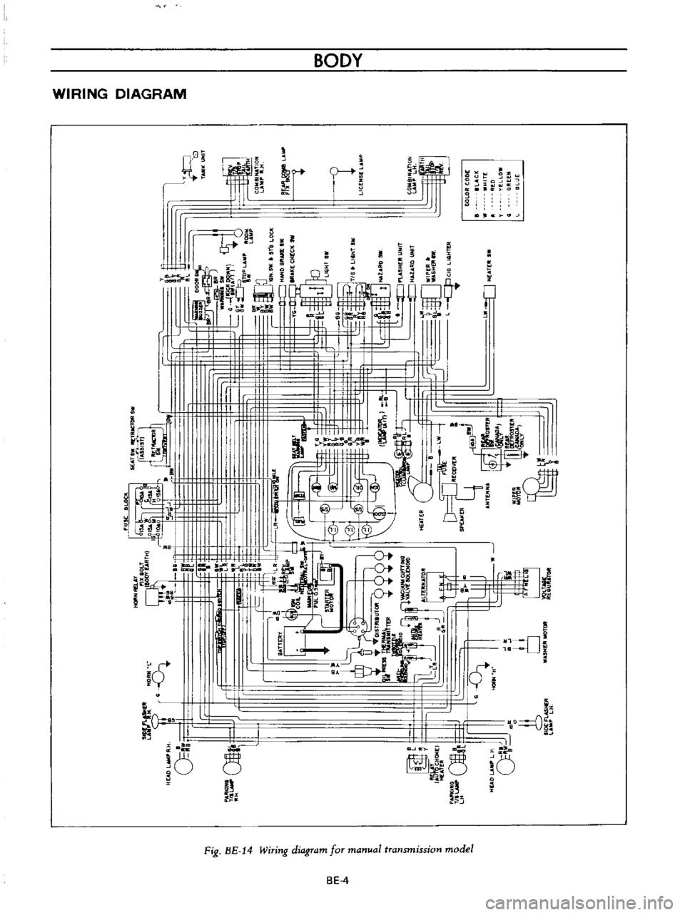
Fig
BE
14
Wiring
diagra
for
an
at
transmission
odel
BE
4
Page 241 of 513

INSPECTION
Referring
to
the
wiring
diagram
check
the
wiring
harness
for
connection
with
electrical
equipment
and
connector
for
conned
ion
and
installation
When
checking
the
wiring
harness
note
the
following
matters
Connected
unit
should
not
be
loose
rusted
or
contaminated
2
Cable
insulator
cover
should
not
be
damaged
crack
ed
or
insulating
material
should
not
be
deteriorated
3
For
those
parts
which
are
grounded
through
the
installation
bolts
the
bolts
should
be
in
contact
with
the
body
completely
so
that
continuity
is
provided
in
between
the
body
and
bolts
4
Terminals
of
unit
through
which
current
flows
should
not
come
into
contact
with
other
metal
parts
5
No
erroneous
connection
should
be
present
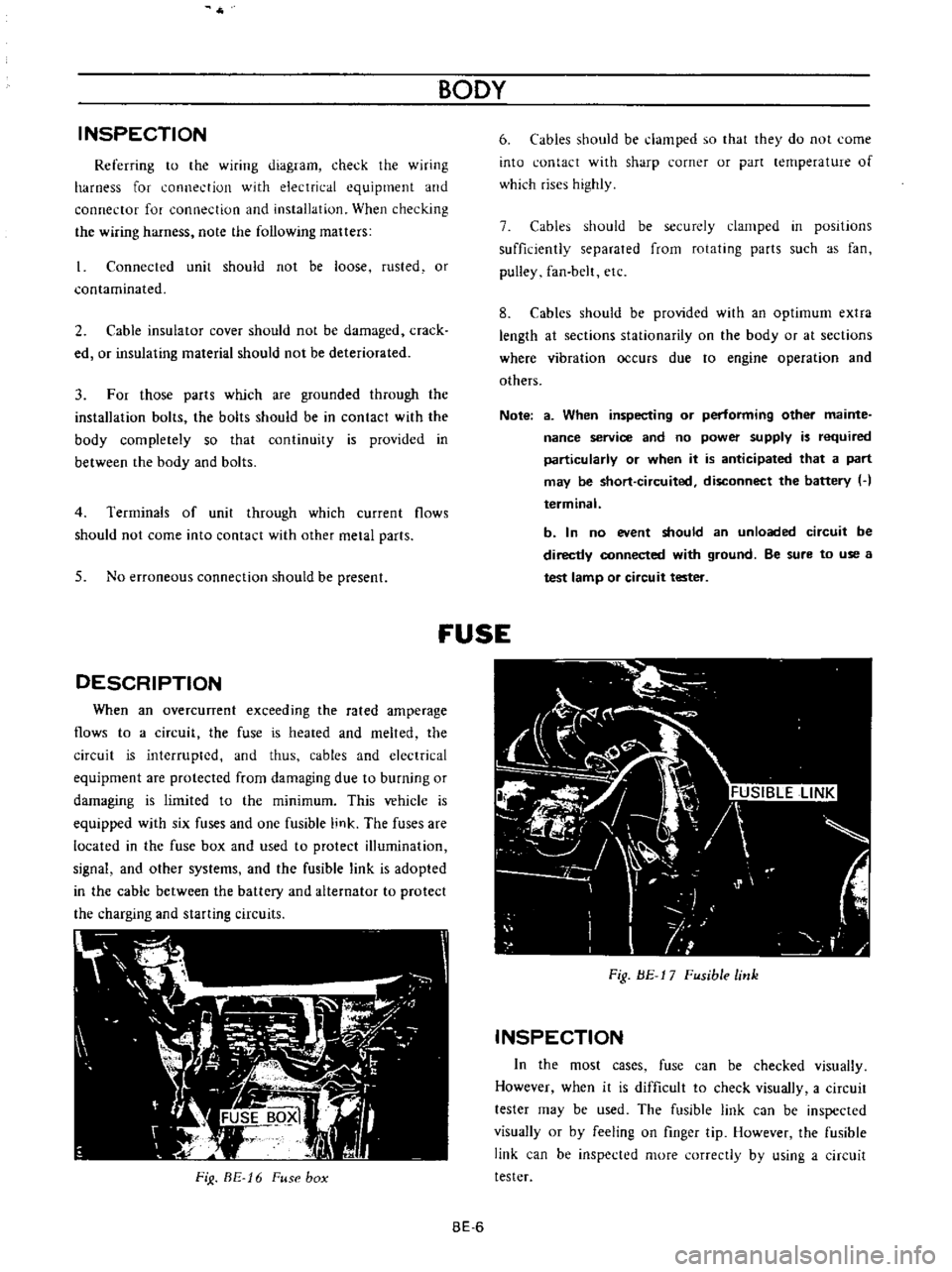
DESCRIPTION
When
an
overcunent
exceeding
the
rated
amperage
flows
to
a
circuit
the
fuse
is
heated
and
melted
the
circuit
is
interrupted
and
thus
cables
and
electrical
equipment
are
protected
from
damaging
due
to
burning
or
damaging
is
limited
to
the
minimum
This
vehicle
is
equipped
with
six
fuses
and
one
fusible
link
The
fuses
are
located
in
the
fuse
box
and
used
to
protect
illumination
signal
and
other
systems
and
the
fusible
link
is
adopted
in
the
cable
between
the
battery
and
alternator
to
protect
the
charging
and
starting
circuits
FiJ
BE
16
Fuse
box
BODY
6
Cables
should
be
damped
so
that
they
do
not
come
into
contact
with
sharp
corner
or
part
lernperature
of
which
rises
highly
7
Cables
should
be
securely
clamped
in
posItions
sufficiently
separated
from
rotating
parts
such
as
fan
pulley
fan
belt
etc
8
Cables
should
be
provided
with
an
optimum
extra
length
at
sections
stationarity
on
the
body
or
at
sections
where
vibration
occurs
due
to
engine
operation
and
others
Note
a
When
inspecting
or
performing
other
mainte
nance
service
and
no
power
supply
is
required
particularly
or
when
it
is
anticipated
that
a
part
may
be
short
circuited
disconnect
the
battery
H
terminal
b
In
no
event
should
an
unloaded
circuit
be
directly
connected
with
ground
Be
sure
to
use
a
test
lamp
or
circuit
tester
fUSE
Fig
BE
17
Fusible
link
INSPECTION
In
the
most
cases
fuse
can
be
checked
visually
However
when
it
is
difficult
to
check
visually
a
circuit
tester
may
be
used
The
fusible
link
can
be
inspected
visually
or
by
feeling
on
finger
tip
However
the
fusible
link
can
be
inspected
more
correctly
by
using
a
circuit
tester
BE
6
Page 242 of 513

BODY
ELECTRICAL
Note
8
When
a
fuse
is
blown
off
be
sure
to
correct
the
cause
before
installing
new
fuse
b
Be
sure
to
use
fuse
having
the
rated
capacity
Do
not
use
fuse
having
larger
capacity
i
e
20A
JOA
etc
c
Particularly
when
the
fusible
link
is
fused
replace
with
a
designated
fusible
link
Green
color
link
for
model
8110
In
comparison
with
fuse
much
higher
current
flows
through
the
fusible
link
Moreover
it
is
important
to
eliminate
the
cause
of
blown
off
fusible
link
before
replacing
d
When
fuse
is
connected
incorrectly
and
the
contact
is
loose
voltage
drops
and
heat
are
gener
ated
resulting
abnormally
operated
electrical
equip
ment
Remove
dust
or
when
oxidized
polish
with
a
fine
emery
paper
so
that
the
contact
is
improved
LlGHTING
SYSTEM
CONTENTS
HEAD
LAMP
Descri
ption
Sealed
beam
replacement
Aiming
adjustment
FRONT
PARKING
AND
TURN
SIGNAL
SIDE
FLASHER
IMARKER
LAMP
AN
D
LICENSE
LAMP
REAR
COMBINATION
LAMPS
BULB
SPECIFICATIONS
TURN
SIGNAL
AND
DIMMER
COMBINATION
SWITCH
BE
7
BE
7
BE
7
BE
8
LAMP
BE
8
BE
9
BE10
BE10
HEAD
LAMP
Description
All
weather
type
sealed
beam
2
light
system
front
lamps
are
adopted
Each
lamp
of
both
side
head
lamps
is
provided
with
high
beam
filament
for
long
range
SOW
and
low
beam
filarnent
for
dipping
40W
In
other
words
the
lamp
is
of
a
double
filament
type
Sealed
beam
replacement
I
Rernove
the
wiring
socket
from
back
of
the
head
lamp
2
Remove
the
screws
attaching
the
front
grille
to
the
radiator
core
support
Coupe
only
Remove
three
retaining
screws
and
remove
the
head
lamp
rim
All
other
than
coupe
3
Loosen
three
screws
used
to
install
the
retaining
ring
on
the
sealed
bearn
mounting
ring
and
remove
the
sealed
Removal
LIGHTING
SWITCH
Removal
HAZARD
WARNING
SWITCH
PASSING
LIGHT
SWITCH
TROUBLE
DIAGNOSES
AND
CORRECTIONS
Head
lamp
Turn
signal
lamps
Tail
and
stop
lamp
license
lamp
back
up
lamp
BE
10
BE
11
BE
11
BE
11
BE
12
BE
12
BE
12
BE
13
BE
15
i
Ii
beam
unit
4
When
installing
a
new
unit
be
sure
to
position
the
Top
mark
to
the
top
of
ring
1
2
Sealed
beam
unit
Sealed
beam
mounting
ring
3
Retaining
ring
4
Aiming
adjusting
screws
Fig
BE
18
Replacing
sealed
beam
BE
7
Page 270 of 513

BODY
ELECTRICAL
heater
unit
on
the
dash
board
and
remove
the
heater
unit
carefully
panel
8
Rernove
two
self
tapping
screws
from
back
of
the
instrument
panel
and
remove
the
defroster
nozzle
7
When
removing
the
heater
control
from
the
instru
ment
panel
remove
the
control
knob
and
loosen
two
screws
used
to
install
the
heater
control
on
the
instrument
9
The
heater
unit
is
installed
in
reverse
sequence
of
removal
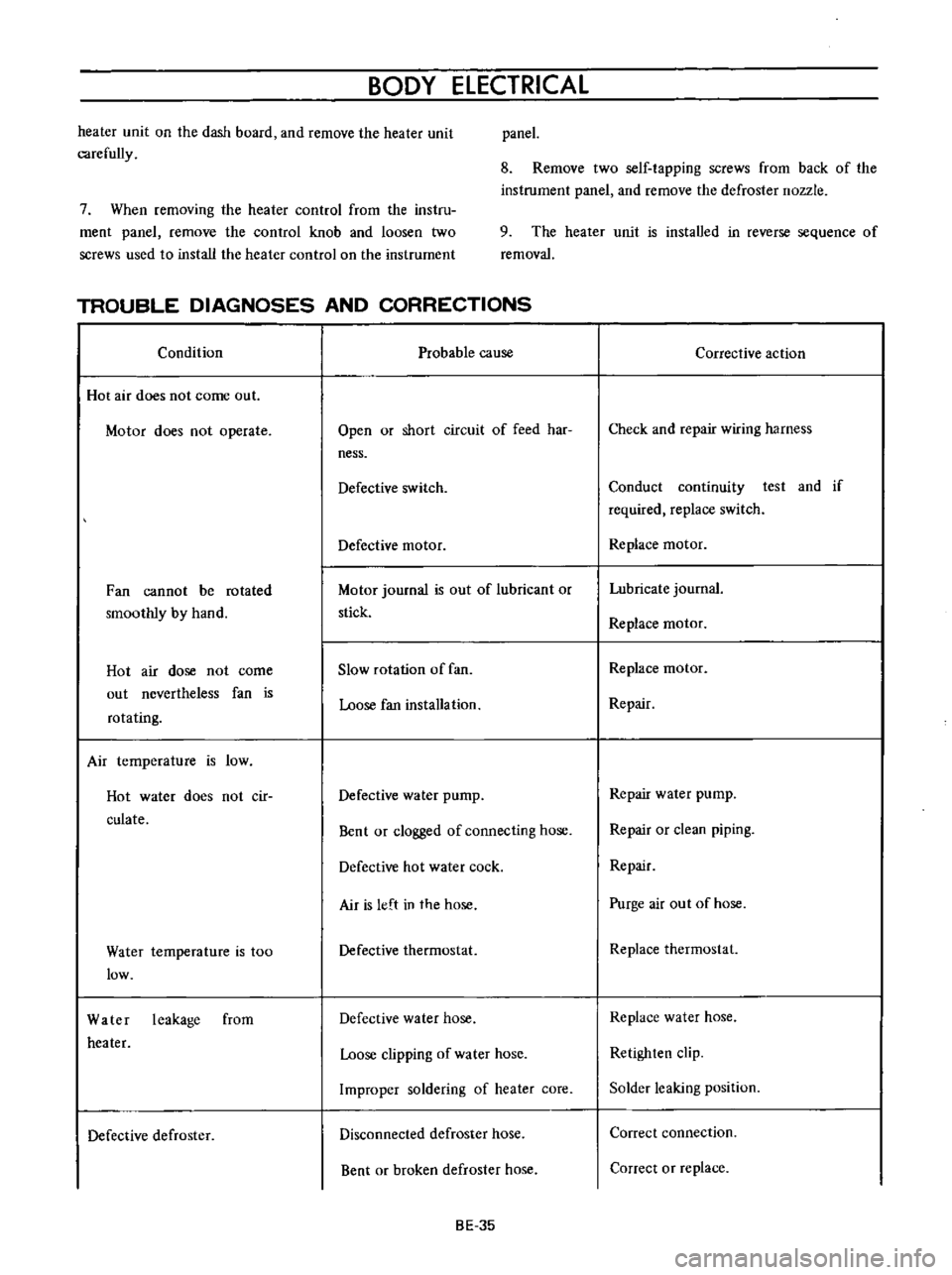
TROUBLE
DIAGNOSES
AND
CORRECTIONS
Condition
Probable
cause
Hot
air
does
not
come
out
Motor
does
not
operate
Open
or
short
circuit
of
feed
har
ness
Defective
switch
Defective
motor
Fan
cannot
be
rotated
smoothly
by
hand
Motor
journal
is
out
of
lubricant
or
stick
Hot
air
dose
not
come
out
nevertheless
fan
is
rotating
Slow
rotation
of
fan
Loose
fan
installation
Air
temperature
is
low
Hot
water
does
not
cir
culate
Defective
water
pump
Bent
or
clogged
of
connecting
hose
Defective
hot
water
cock
Air
is
left
in
the
hose
Water
temperature
is
too
low
Defective
thermostat
Water
leakage
from
heater
Defective
water
hose
Loose
clipping
of
water
hose
Improper
soldering
of
heater
core
Defective
defroster
Disconnected
defroster
hose
Bent
or
broken
defroster
hose
BE
35
Corrective
action
Check
and
repair
wiring
harness
Conduct
continuity
test
and
if
required
replace
switch
Replace
motor
Lubricate
journal
Replace
motor
Replace
motor
Repair
Repair
water
pump
Repair
or
clean
piping
Repair
Purge
air
out
of
hose
Replace
thermostat
Replace
water
hose
Retighten
clip
Solder
leaking
position
Correct
connection
Correct
or
replace
Page 306 of 513

EMISSION
CONTROL
AND
TUNE
UP
EMISSION
CONTROL
SYSTEM
AN
D
ENGINE
TUNE
UP
CONTENTS
BASIC
MECHANICAL
SYSTEM
ET
Checking
and
adjusting
dash
pot
Adjusting
intake
and
exhaust
valve
automatic
transmission
model
only
ET
9
clearances
ET
1
Checking
carburetor
return
spring
ET
9
Checking
and
adjustin9
drive
belt
ET
2
Checking
choke
mechanism
choke
valve
Retightening
cylinder
head
bolts
manifold
and
linkagel
ET
9
nuts
and
carburetor
securing
nuts
ET
2
Checking
anti
dieseling
solenoid
ET
9
Checking
engine
oil
ET
2
Replacing
fuel
filter
ET
10
Replacing
oil
filter
ET
3
Checking
fuel
lines
hoses
pipings
Changing
engine
coolant
L
L
C
ET
3
connections
etc
ET10
Checking
cooling
system
hoses
and
THROTTLE
OPENER
CONTROL
SYSTEM
ET
10
connections
ET
4
Checking
and
adjusting
throttle
opener
ET
13
Checking
vacuum
fittings
hoses
and
TRANSMISSION
CONTROLLED
VACUUM
connections
ET
4
ADVANCE
SYSTEM
ET
17
Checking
engine
compression
ET
4
Checking
electrical
advance
control
system
ET
19
Checking
exhaust
manifold
heat
control
AUTOMATIC
TEMPERATURE
CONTROL
AIR
valve
ET
5
CLEANER
A
T
C
AIR
CLEANER
ET
20
IGNITION
AND
FUEL
SYSTEM
ET
5
Replacing
carburetor
air
cleaner
filter
ET
20
Checking
battery
ET
5
Checking
hot
air
control
valve
ET
20
Checking
and
adjusting
ignition
timing
ET
5
CRANKCASE
EMISSION
CONTROL
Checking
or
replacing
distributor
breaker
SYSTEM
ET
22
point
condenser
and
spark
plugs
ET
6
Checking
or
replacing
PCV
valve
ET
23
Checking
distributor
ignition
wiring
and
Checking
ventilation
hoses
ET
23
ignition
coil
ET
7
EVAPORATIVE
EMISSION
CONTROL
Checking
distributor
cap
and
rotor
ET
7
SYSTEM
ET
23
Adjusting
carburetor
id
Ie
rpm
and
Checking
engine
compartment
hose
mixture
ratio
ET
8
connections
and
fuel
vapor
control
valves
ET
23
Checking
fuel
tank
vacuum
relief
valve
operation
ET
24
BASIC
MECHANICAL
SYSTEM
1
Start
engine
and
run
it
until
it
is
heated
to
operating
temperature
or
at
least
more
than
800C
I760F
of
engine
oil
temperature
then
stop
engine
Adjusting
intake
and
exhaust
valve
clearances
Valve
clearance
adjustment
should
be
made
while
engine
is
stationary
To
adjust
proceed
as
follows
2
Rotate
crankshaft
to
bring
No
1
cylinder
in
top
dead
center
on
its
compression
stroke
3
Remove
valve
rocker
cover
to
gain
access
to
valve
ET
1
Page 312 of 513

EMISSION
CONTROL
AND
TUNE
UP
Fig
ET
11
Checking
spark
plug
gap
Checking
distributor
ignition
wiring
and
ignition
coil
Distributor
Check
centrifugal
advance
unit
for
loose
connection
or
improper
operation
If
it
is
not
operating
properly
the
trouble
may
be
due
to
a
sticky
spring
or
excessively
worn
parts
This
operation
needs
a
distributor
tester
As
to
inspection
procedure
and
reference
data
refer
to
relative
topic
under
Distributor
in
Section
EE
Page
EE
32
If
vacuum
advance
mechanism
fails
to
operate
proJr
erly
check
for
the
following
items
and
correct
the
trouble
as
required
1
Check
vacuum
inlet
for
signs
of
leakage
at
its
connection
If
necessary
retighten
or
replace
with
a
new
one
2
Check
vacuum
diaphragm
for
air
leak
If
leak
is
found
replace
diaphragm
with
a
new
one
3
Inspect
breaker
plate
for
smooth
moving
If
plate
does
not
move
smoothly
this
condition
could
be
due
to
sticky
steel
balls
or
pivot
Apply
grease
to
steel
balls
or
if
necessary
replace
breaker
plate
as
an
assembly
For
vacuum
advance
characteristics
refer
to
Distribu
tor
in
Section
EE
Page
EE
32
Ignition
wiring
Use
an
ohmmeter
to
check
resistance
of
secondary
cables
Disconnect
cables
from
spark
plugs
and
install
the
proper
adapter
between
cable
and
spark
plug
Remove
distributor
cap
from
the
distributor
with
secondary
cables
attached
Do
not
remove
the
cables
from
the
cap
Check
the
resistance
of
one
cable
at
a
time
Connect
the
ohmmeter
between
the
spark
plug
adapter
and
the
corresponding
electrode
inside
the
cap
If
resistance
is
more
than
30
000
ohms
remove
the
cable
from
the
cap
and
check
cable
resistance
only
If
the
resistance
is
still
more
than
30
000
ohms
replace
cable
assembly
T
I
II
Fig
ET
12
Checking
high
tension
cables
Ignition
coil
Check
ignition
coil
for
appearance
oil
leakage
or
performance
For
details
refer
to
Section
EE
Page
EE36
Checking
distributor
cap
and
rotor
Note
This
operation
is
to
be
performed
while
chekcing
distribuotr
points
Inspect
distributor
cap
for
cracks
and
flash
over
External
surfaces
of
all
parts
of
secondary
system
must
be
cleaned
to
reduce
possibility
of
voltage
loss
All
wires
should
be
removed
from
distributor
cap
and
coil
so
that
terminals
can
be
inspected
and
cleaned
Burned
or
corroded
terminals
indicate
that
wires
were
not
fully
seated
which
causes
arcing
between
end
of
wire
and
terminal
When
replacing
wires
in
terminal
be
sure
they
are
fully
seated
before
pushing
rubber
nipple
down
over
tower
Check
distributor
rotor
for
damage
and
distributor
cap
for
cracks
ET
7