1973 DATSUN B110 fuel pressure
[x] Cancel search: fuel pressurePage 253 of 513

BODY
METERS
AND
GAUGES
CONTENTS
CLUSTER
LID
Oescri
ption
Removal
SPEEDOMETER
Replacement
FUEL
GAUGE
AND
TEMPERATURE
GAUGE
Description
Replacement
BE
1B
BE
18
BE
18
BE
19
BE
19
BE
19
BE
19
BE
20
CLUSTER
LID
Description
The
cluster
lid
holds
various
rneters
indicators
and
clock
located
around
the
speedorneter
Printed
circuit
board
is
used
at
the
back
of
the
meter
as
shown
in
Figure
BE
38
and
the
printed
circuit
board
is
connected
with
multiple
connectors
Thus
the
meters
Can
be
inspected
and
serviced
extremely
easily
Except
for
the
speed
ometer
all
rneters
are
operated
electrically
The
fuel
gauge
and
therrnometer
are
very
reliable
and
they
are
equipped
with
bimetal
devices
F
a
o
ill
I
1
a
a
Fig
BE
34
Combination
meters
Removal
Disconnect
the
battery
terminal
depressing
the
OIL
PRESSURE
AND
IGNITION
WARNING
LAMPS
HAND
BRAKE
WARNING
LAMP
BULB
SPECIFICATIONS
TROUBLE
DIAGNOSES
AND
CORRECTIONS
Speedometer
Thermometer
and
fuel
meter
Oil
pressure
and
ignition
warning
lamps
BE
20
BE
21
BE
21
BE
22
BE
22
BE
23
BE
25
windshield
wiper
switch
lighting
switch
and
choke
lever
knobs
turn
them
counterclockwise
to
remove
Remove
the
escutcheon
2
Inserting
your
hand
into
back
of
the
cluster
lid
disconnect
the
cigarette
lighter
cable
and
turn
and
remove
the
cigarette
lighter
outer
case
3
Remove
the
radio
and
heater
control
knobs
4
Remove
the
shell
cover
from
the
steering
tube
loosen
the
screws
used
to
secure
the
meter
housing
to
the
instrument
panel
and
remove
the
cluster
lid
5
Pull
out
the
l2
pole
round
shape
connector
and
remove
the
speedometer
cable
union
nut
6
Remove
the
cluster
lid
from
the
instrument
panel
Fig
BE
35
Removing
clllSter
jd
BE
18
Page 255 of 513
BODY
REGULATOR
FUSE
M
TEMPE
RATURE
GAUGE
IGNITION
SWITCH
Lf
I
iT
Ji
1M
THERMAL
TRANSMITTER
I
J
0
I
GAUGE
TANK
UNIT
FUEL
TANK
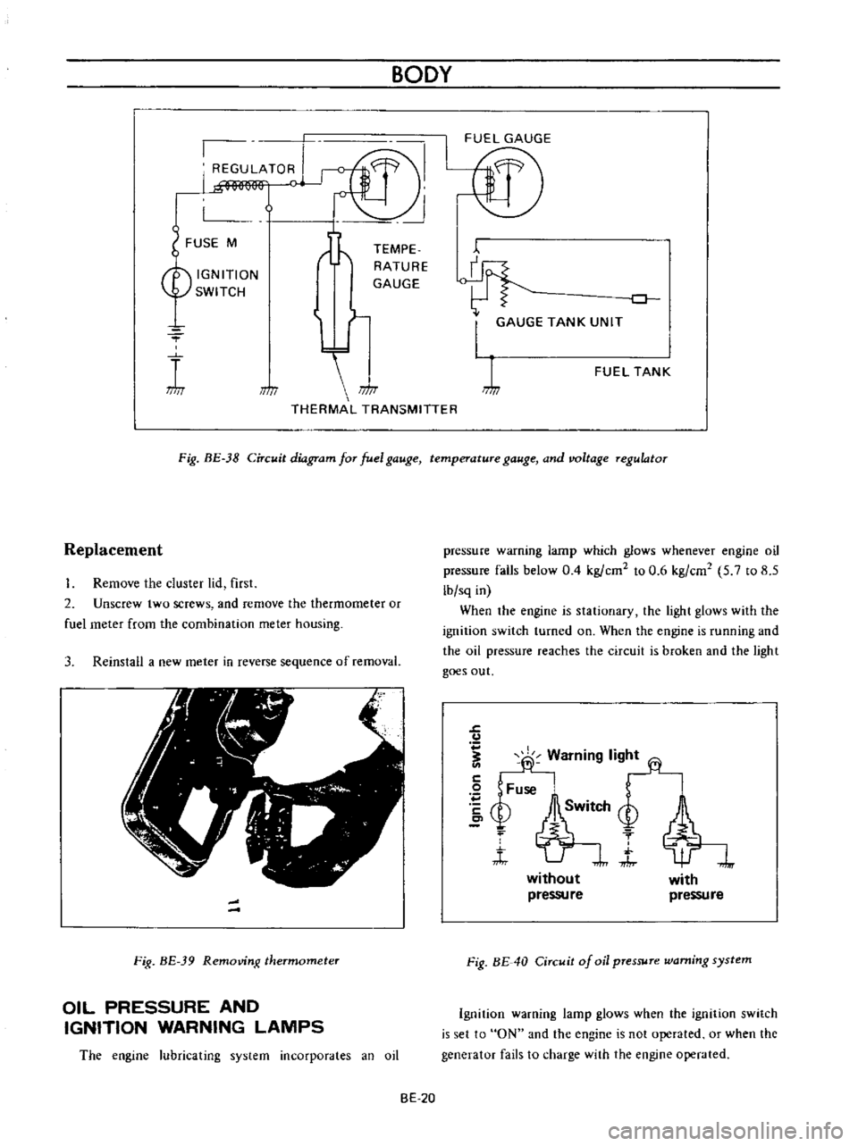
Fig
BE
38
Circuit
diagram
for
fuel
gauge
temperature
gauge
and
voltage
regulator
Replacement
Remove
the
cluster
lid
first
2
Unscrew
two
screws
and
remove
the
thermometer
or
fuel
meter
from
the
combination
meter
housing
3
Reinstall
a
new
meter
in
reverse
sequence
of
removal
Fig
BE
39
Removing
thermometer
OIL
PRESSURE
AND
IGNITION
WARNING
LAMPS
The
engine
lubricating
system
incorporates
an
oil
pressure
warning
lamp
which
glows
whenever
engine
oil
pressure
falls
below
0
4
kg
ern
to
0
6
kg
em
5
7
to
8
5
lb
sq
in
When
the
engine
is
stationary
the
light
glows
with
the
ignition
switch
turned
on
When
the
engine
is
running
and
the
oil
pressure
reaches
the
circuit
is
broken
and
the
light
goes
out
J
u
fj
Warning
lig
2
Fuse
bSM
Q
f
t
J
without
pressu
re
with
pressure
Fig
BE
40
Circuit
of
oil
pressure
warning
system
Ignition
warning
lamp
glows
when
the
ignition
switch
is
set
to
ON
and
the
engine
is
not
operated
or
when
the
generator
fails
to
charge
with
the
engine
operated
BE
20
Page 260 of 513

BODY
ELECTRICAL
Improper
cable
contact
Oil
pressure
and
ignition
warning
lamps
Condition
Oil
pressure
Want
ing
lamp
The
lamp
does
not
ligh
t
when
the
ignition
switch
is
set
to
ON
Probable
cause
Blown
off
fuse
or
faulty
contact
Broken
lamp
bulb
fIlarnent
or
faulty
cable
contact
Defective
oil
pressure
switch
The
lamp
does
not
Oil
pressure
is
too
low
go
out
while
the
engine
is
being
operated
Lack
of
engine
oil
Defective
oil
pressure
switch
Ignition
warning
lamp
The
lamp
does
not
light
when
the
ignition
switch
is
set
to
ON
Blown
off
fuse
or
faulty
contact
Burnt
out
light
bulb
filarnent
or
faulty
cable
contact
The
fuel
rneter
indicates
a
level
slightly
lower
than
the
actual
level
Method
of
inspection
Check
the
fuse
for
fusing
and
faulty
contact
The
warning
lamp
does
not
light
when
oil
pressure
switch
yellow
black
cable
is
grounded
The
warning
lamp
lights
through
the
above
inspection
Inspect
the
engine
oil
pressure
system
Check
oil
level
Continuity
exists
on
the
oil
pres
sure
switch
when
the
engine
is
being
operated
Check
the
fuse
for
fusing
and
faulty
contact
The
pilot
lamp
does
not
light
when
the
voltage
regulator
con
nector
is
disconnected
the
white
red
cable
is
grounded
and
the
ignition
switch
is
set
to
ON
BE
25
Check
the
cable
from
the
fuel
meter
to
the
tank
unit
for
cable
being
about
to
break
poor
contact
and
faulty
grounding
and
repair
as
required
Corrective
action
Replace
after
corree
ting
the
fuse
the
cause
if
fused
Check
the
light
bulb
for
burnt
out
fIla
ment
and
replace
as
required
Replace
the
oil
pres
sure
switch
Add
oil
Replace
the
oil
pres
sure
switch
Repair
or
replace
as
required
Check
the
bulb
for
burnt
out
fIlament
and
replace
as
re
quired
Page 310 of 513

EMISSION
CONTROL
AND
TUNE
UP
reading
cylinders
through
spark
plug
hole
Repeat
compression
check
on
these
cylinders
1
If
compression
improves
considerably
piston
rings
are
defective
2
If
compression
does
not
improve
valves
are
sticking
or
seating
improperly
3
If
two
adjacent
cylinders
indicate
low
compression
and
injecting
oil
on
pistons
does
not
increase
compres
sion
the
cause
may
be
a
cylinder
head
gasket
leak
between
the
cylinders
Engine
oil
and
coolant
in
cylinder
could
result
from
this
problem
Compression
pressure
12
S
to
14
S
kg
cm2
178
to
206
psi
at
3S0
rpm
Checking
exhaust
manifold
heat
control
valve
Check
heat
control
valve
for
proper
operation
If
it
does
not
operate
properly
trouble
is
due
to
excess
carbon
on
shaft
or
damaged
shaft
Clean
if
necessary
The
bimetal
should
be
also
checked
for
proper
function
IGNITION
AND
FUEL
SYSTEM
Checking
battery
Check
electrolyte
level
in
each
battery
celL
L
Unscrew
each
filler
cap
and
inspect
fluid
leveL
If
fluid
level
is
low
add
distilled
water
to
bring
level
up
to
app
roximately
10
to
20
mm
0
3937
to
0
7874
in
above
plates
Do
not
overfilL
2
Measure
specific
gravity
of
battery
electrolyte
ET002
Fig
ET
B
Checking
the
specific
gravity
of
battery
electrolyte
Permissible
Full
charge
value
value
at
200C
68OF
Frigid
climates
Over
1
22
1
28
Tropical
climates
Over
1
18
1
23
Other
climates
Over
L
20
1
26
Clean
the
top
of
battery
and
terminals
with
a
solu
lion
of
baking
soda
and
water
Rinse
off
and
dry
with
compressed
air
The
top
of
battery
must
be
clean
to
prevent
current
leakage
between
terminals
and
from
positive
terminal
to
hold
down
clamp
In
addition
to
current
leakage
prolonged
accumulation
of
acid
and
dirt
on
the
top
of
battery
may
cause
blistering
of
the
material
covering
connector
straps
and
corrosion
of
straps
After
tightening
terminals
coat
them
with
petro
laturn
vaseline
to
protect
them
from
corrosion
Checking
and
adjusting
ignition
timing
I
Check
spark
plugs
and
distributor
breaker
points
for
condition
2
Thoroughly
wipe
off
dirt
and
dust
from
timing
marks
on
crank
pulley
and
front
cover
3
Warm
up
engine
sufficiently
ET
5
Page 315 of 513
ENGINE
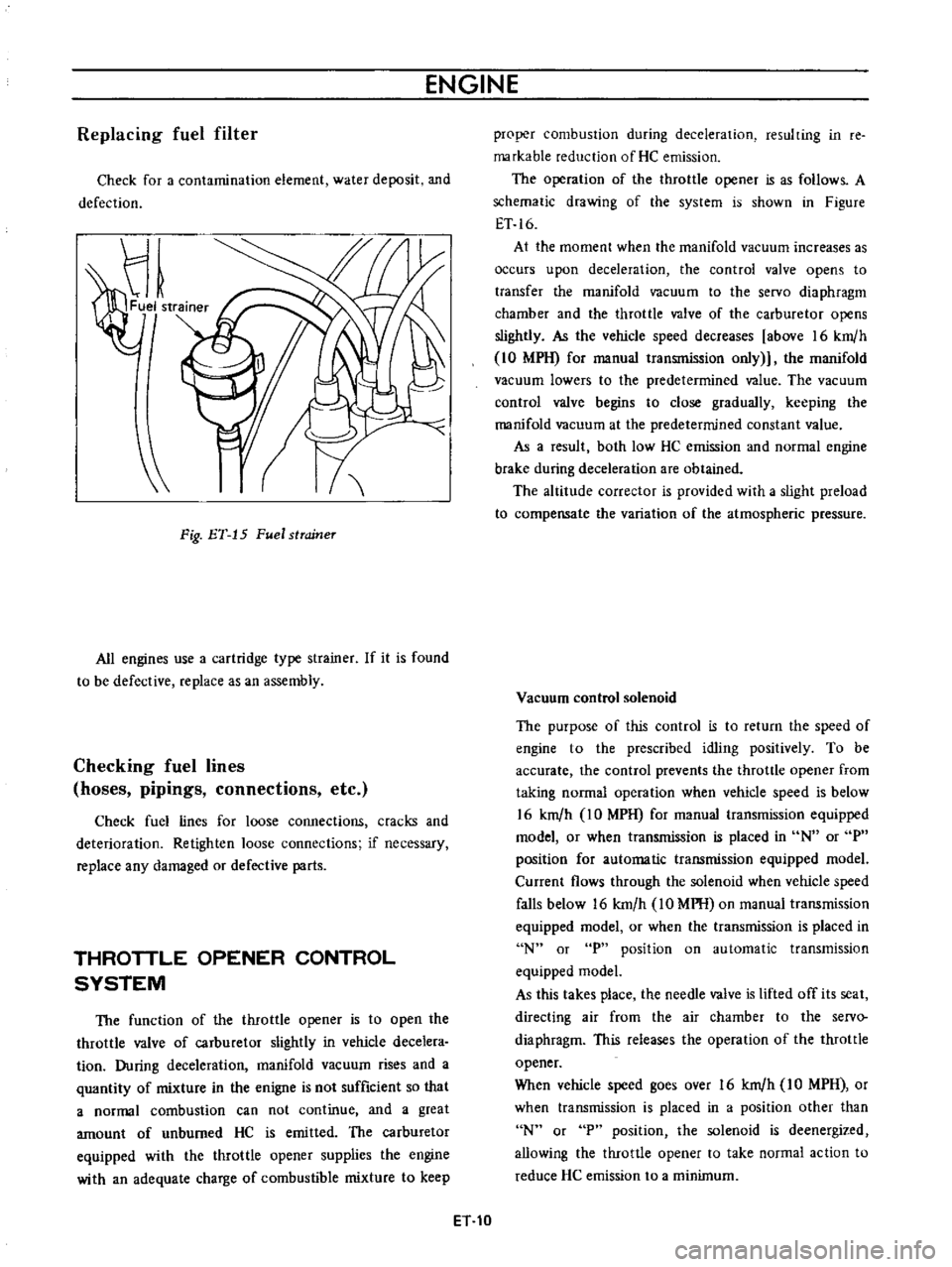
Replacing
fuel
filter
Check
for
a
contamination
element
water
deposit
and
defection
Fig
ET
15
Fuel
strcrineT
All
engines
use
a
cartridge
type
strainer
If
it
is
found
to
be
defective
replace
as
an
assembly
Checking
fuel
lines
hoses
pipings
connections
etc
Check
fuel
lines
for
loose
connections
cracks
and
deterioration
Retighten
loose
connections
if
necessary
replace
any
damaged
or
defective
parts
THROTTLE
OPENER
CONTROL
SYSTEM
The
function
of
the
throttle
opener
is
to
open
the
throttle
valve
of
carburetor
slightly
in
vehicle
decelera
tion
During
deceleration
manifold
vacuum
rises
and
a
quantity
of
mixture
in
the
enigne
is
not
sufficient
so
that
a
normal
combustion
can
not
continue
and
a
great
amount
of
unburned
HC
is
emitted
The
carburetor
equipped
with
the
throttle
opener
supplies
the
engine
with
an
adequate
charge
of
combustible
mixture
to
keep
proper
combustion
during
deceleration
resulting
in
re
markable
reduction
of
He
emission
The
operation
of
the
throttle
opener
is
as
follows
A
schematic
drawing
of
the
system
is
shown
in
Figure
ET
16
At
the
moment
when
the
manifold
vacuum
increases
as
occurs
upon
deceleration
the
control
valve
opens
to
transfer
the
manifold
vacuum
to
the
servo
diaphragm
chamber
and
the
throttle
valve
of
the
carburetor
opens
slightly
As
the
vehicle
speed
decreases
above
16
km
h
10
MPH
for
manual
transmission
only
the
manifold
vacuum
lowers
to
the
predetermined
value
The
vacuum
control
valve
begins
to
close
gradually
keeping
the
manifold
vacuum
at
the
predetermined
constant
value
As
a
result
both
low
HC
emission
and
normal
engine
brake
during
deceleration
are
obtained
The
altitude
corrector
is
provided
with
a
slight
preload
to
compensate
the
variation
of
the
atmospheric
pressure
Vacuum
control
solenoid
The
purpose
of
this
control
is
to
return
the
speed
of
engine
to
the
prescribed
idling
positively
To
be
accurate
the
control
prevents
the
throttle
opener
from
taking
normal
operation
when
vehicle
speed
is
below
16
km
h
IO
MPH
for
manual
transmission
equipped
model
or
when
transmission
is
placed
in
N
or
P
position
for
automatic
transmission
equipped
model
Current
flows
through
the
solenoid
when
vehicle
speed
falls
below
16
km
h
10
MPH
on
manual
transmission
equipped
model
or
when
the
transmission
is
placed
in
N
or
P
position
on
automatic
transmission
equipped
model
As
this
takes
place
the
needle
valve
is
lifted
off
its
seat
directing
air
from
the
air
chamber
to
the
servo
diaphragm
This
releases
the
operation
of
the
throttle
opener
When
vehicle
speed
goes
over
16
km
h
IO
MPH
or
when
transmission
is
placed
in
a
position
other
than
N
or
P
position
the
solenoid
is
deenergized
allowing
the
throttle
opener
to
take
normal
action
to
reduce
He
emission
to
a
minimum
ET
10
Page 329 of 513
ENGINE
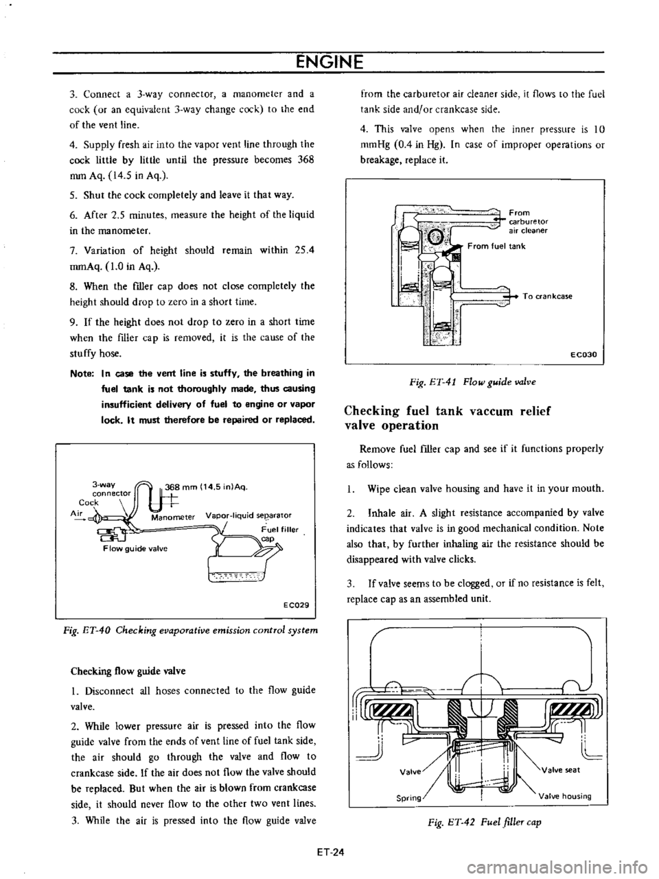
3
Connect
a
3
way
connector
a
manometer
and
a
cock
or
an
equivalent
3
way
change
cock
to
the
end
of
the
vent
line
4
Supply
fresh
air
into
the
vapor
vent
line
through
the
cock
little
by
little
until
the
pressure
becomes
368
mm
Aq
14
5
in
Aq
5
Shut
the
cock
completely
and
leave
it
that
way
6
After
2
5
minutes
measure
the
height
of
the
liquid
in
the
manometer
7
Variation
of
height
should
remain
within
254
mmAq
1
0
in
Aq
8
When
the
filler
cap
does
not
close
completely
the
height
should
drop
to
zero
in
a
short
time
9
If
the
height
does
not
drop
to
zero
in
a
short
time
when
the
filler
cap
is
removed
it
is
the
cause
of
the
stuffy
hose
Note
In
case
the
vent
line
is
stuffy
the
breathing
in
fuel
tank
is
not
thoroughly
made
thus
causing
insufficient
delivery
of
fuel
to
engine
or
vapor
lock
It
must
therefore
be
repaired
or
replaced
3
way
connector
Cock
Air
Manometer
Vapor
liquid
seearator
Flow
guide
valve
E
CQ29
Fig
ET
40
Checking
evaporative
emission
control
system
Checking
flow
guide
valve
I
Disconnect
all
hoses
connected
to
the
flow
guide
valve
2
While
lower
pressure
air
is
pressed
into
the
flow
guide
valve
from
the
ends
of
vent
line
of
fuel
tank
side
the
air
should
go
through
the
valve
and
flow
to
crankcase
side
If
the
air
does
not
flow
the
valve
should
be
replaced
But
when
the
air
is
blown
from
crankcase
side
it
should
never
flow
to
the
other
two
vent
lines
3
While
the
air
is
pressed
into
the
flow
guide
valve
from
the
carburetor
air
cleaner
side
it
flows
to
the
fuel
tank
side
and
or
crankcase
side
4
This
valve
opens
when
the
inner
pressure
is
10
mmHg
0
4
in
Hg
In
case
of
improper
operations
or
breakage
replace
it
From
carburetor
air
cleaner
From
fuel
tank
i
I
I
ti
i
i
1
1
i
To
ran
kcase
E
C030
Fig
ET
41
Flow
guide
valve
Checking
fuel
tank
vaCCUID
relief
valve
operation
Remove
fuel
filler
cap
and
see
if
it
functions
properly
as
follows
Wipe
clean
valve
housing
and
have
it
in
your
mouth
2
Inhale
air
A
slight
resistance
accompanied
by
valve
indicates
that
valve
is
in
good
mechanical
condition
Note
also
that
by
further
inhaling
air
the
resistance
should
be
disappeared
with
valve
clicks
3
If
valve
seems
to
be
clogged
or
if
no
resistance
is
felt
replace
cap
as
an
assembled
unit
T
1i
v
rUr1f
AlI
j
r
I
r
tLMJJl
rr
L
cc
11
J
v
II
4J
L
Valve
I
valve
seat
Spring
Valve
housing
Fig
ET
42
Fuel
filler
cap
ET
24
Page 335 of 513
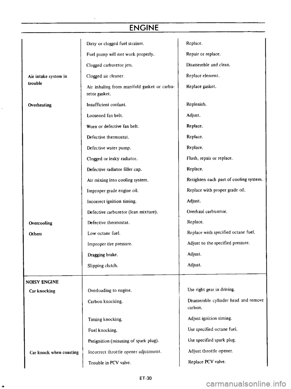
Air
intake
system
in
trouble
Overheating
Overcooling
Others
NOISY
ENGINE
Car
knocking
Car
knock
when
coasting
ENGINE
Diny
ur
clogged
fuel
strainer
Fuel
pump
will
not
work
properly
Clogged
carburetor
jets
Clogged
air
cleaner
Air
inhaling
from
manifold
gasket
or
carbu
retor
gasket
Insufficient
coolant
Loosened
fan
belt
Worn
or
defective
fan
belt
Defective
thermostat
Defective
water
pump
Clogged
or
leaky
radiator
Defective
radiator
filler
cap
Air
mixing
into
cooling
system
Improper
grade
engine
oil
Incorrect
ignition
timing
Defective
carburetor
lean
mixture
Defective
thermostat
Low
octane
fuel
Improper
tire
pressure
Dragging
brake
Slipping
clutch
Overloading
to
engine
Carbon
knocking
Timing
knocking
Fuel
knocking
Preignition
misusing
of
spark
plug
Incorrect
throttle
opener
adjustment
Trouble
in
PCV
valve
ET
30
Replace
Repair
or
replace
Disassemble
and
clean
Replace
element
Replace
gasket
Replenish
Adjust
Replace
Replace
Replace
Flush
repair
or
replace
Replace
Retighten
each
part
of
cooling
system
Replace
with
proper
grade
oil
Adjust
Overhaul
carburetor
Replace
Replace
with
specified
octane
fuel
Adjust
to
the
specified
pressure
Adjust
Adjust
Use
right
gear
in
driving
Disassemble
cylinder
head
and
remove
carbon
Adjust
ignition
timing
Use
specified
octane
fuel
Use
specified
spark
plug
Adjust
throttle
opener
Replace
PCV
valve
Page 337 of 513
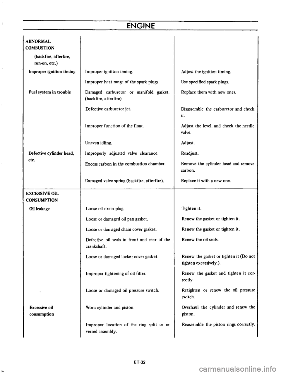
ABNORMAL
COMBUSTION
backfire
afterflfe
run
on
etc
Improper
ignition
timing
Fuel
system
in
trouble
Defective
cylinder
head
etc
EXCESSIVE
OIL
CONSUMPTION
Oil
leakage
Excessive
oil
consumption
ENGINE
Improper
ignition
timing
Improper
heat
range
of
the
spark
plugs
Damaged
carburetor
or
manifold
gasket
backfire
afterflre
Defective
carburetor
jet
Improper
function
of
the
float
Uneven
idling
Improperly
adjusted
valve
clearance
Excess
carbon
in
the
combustion
chamber
Damaged
valve
spring
backfire
afterure
Loose
oil
drain
plug
Loose
or
damaged
oil
pan
gasket
Loose
or
damaged
chain
cover
gasket
Defective
oil
seals
in
front
and
rear
of
the
crankshaft
Loose
or
damaged
locker
cover
gasket
Improper
tightening
of
oil
filter
Loose
or
damaged
oil
pressure
switch
Worn
cylinder
and
piston
Improper
location
of
the
ring
split
or
reo
versed
assembly
ET
32
Adjust
the
ignition
timing
Use
specified
spark
plugs
Replace
them
with
new
ones
Disassemble
the
carburetor
and
check
it
Adjust
the
level
and
check
the
needle
valve
Adjust
Readjust
Remove
the
cylinder
head
and
remove
carbon
Replace
it
with
a
new
one
Tighten
it
Renew
the
gasket
or
tighten
it
Renew
the
gasket
or
tighten
it
Renew
the
oil
seals
Renew
the
gasket
or
tighten
it
Do
not
tighten
excessively
Renew
the
gasket
and
tighten
it
cor
rectly
Retighten
or
renew
the
oil
pressure
switch
Overhaul
the
cylinder
and
renew
the
piston
Reassemble
the
piston
rings
correctly