1973 DATSUN B110 change time
[x] Cancel search: change timePage 13 of 513

Low
in
the
range
I
is
led
to
the
low
and
reverse
clutch
from
the
line
pressure
5
through
the
line
pressure
12
and
at
the
same
time
the
same
is
led
to
the
left
end
spring
unit
Consequently
although
the
go
vernor
pressure
increases
the
valve
is
still
depressed
toward
the
right
and
the
SFV
is
fixed
in
the
Low
posi
tion
When
kicked
down
at
the
2nd
speed
the
SDV
operates
and
the
line
pressure
13
depresse
the
FSV
to
ward
the
right
Although
the
governor
pressure
15
is
considerably
high
the
valve
is
depressed
completely
toward
the
right
and
the
FSV
is
returned
to
the
Low
position
This
operation
is
called
Kick
down
shift
2nd
3rd
shift
valve
SSV
The
SSV
is
a
transfer
vaIve
which
shifts
speed
from
2nd
to
3rd
When
the
vehicle
is
stopped
the
SSV
is
depressed
toward
the
right
by
the
spring
and
is
in
the
2nd
position
It
is
provided
however
that
the
FSV
decides
the
shifting
either
to
Low
or
2nd
When
the
vehicle
is
running
the
governor
pressure
15
is
applied
to
the
right
end
surface
and
the
SSV
is
depressed
toward
the
left
Contrarily
the
spring
force
line
pressure
3
and
throttle
pressure
19
depress
the
SSV
toward
the
right
When
the
vehicle
speed
exceeds
a
certain
level
the
governor
pressure
exceeds
the
sum
of
the
spring
force
line
pressure
and
throttle
pressure
the
valve
is
depressed
toward
the
left
and
the
line
pressure
3
is
closed
Conse
quently
the
forces
are
rapidly
un
balanced
the
force
to
depress
the
SSV
toward
the
right
reduces
and
thus
the
SSV
is
depressed
to
the
Ie
ft
end
for
a
moment
With
the
SSV
depressed
to
ward
the
left
end
the
line
pressure
3
is
connected
with
the
line
pressure
10
the
band
servo
is
released
the
front
clutch
is
engaged
and
speed
is
shifted
to
3rd
When
the
accelerator
pedal
is
de
pressed
both
the
line
pressure
3
and
the
throttle
pressure
19
are
high
and
AUTOMATIC
TRANSMISSION
therefore
the
SSV
is
retained
in
2nd
unless
ihe
governor
pressure
IS
exceeds
the
line
pressure
3
and
the
throttle
pressure
19
In
the
3rd
position
force
to
depress
the
SSV
toward
the
right
is
remained
only
on
the
throttle
pressure
16
and
the
throttle
pressure
16
is
slightly
lower
than
that
toward
the
right
which
is
applied
while
shifting
from
2nd
to
3rd
Consequently
the
SSV
is
returned
to
the
2nd
position
at
a
slightly
low
speed
side
Shifting
from
3rd
to
2nd
occurs
at
a
speed
slightly
lower
than
that
for
2nd
to
3rd
shifting
When
kicked
down
at
the
3rd
line
pressure
13
is
led
from
the
SDV
and
the
SSV
is
depressed
toward
the
right
Although
the
governor
pressure
is
considerably
high
the
valve
is
de
pressed
completely
toward
the
right
and
thus
the
SSV
is
returned
to
2nd
position
This
operation
is
called
Kick
down
shift
When
the
shift
lever
is
shifted
to
2
or
I
range
at
the
3rd
speed
the
line
pressure
3
is
drained
at
the
MNV
Consequently
the
front
clutch
operating
and
band
servo
releasing
oils
are
drained
As
the
res
lIt
the
trans
mission
is
shifted
to
the
2nd
or
low
speed
although
the
SSV
is
in
the
3rd
position
When
the
speed
is
shifted
to
the
3rd
a
one
way
orifice
24
on
the
top
of
the
SSV
relieves
oil
transmitting
velocity
from
the
line
pressure
3
to
the
line
pressure
10
and
reduces
a
shock
generated
from
the
shifting
Contrarily
when
shifted
from
3rd
to
2
or
range
and
the
speed
is
shifted
to
the
2nd
spring
of
the
orifice
24
is
depressed
the
throttle
becomes
ineffective
the
line
pressure
10
is
drained
quickly
and
thus
delay
in
the
speed
shifting
is
elimi
nated
Throttle
of
the
line
pressure
6
relieves
the
oil
transmitting
velocity
from
the
line
pressure
6
to
the
line
pressure
10
when
the
lever
is
shifted
to
the
R
range
and
relieves
drain
velocity
from
the
line
pressure
10
to
the
line
pressure
6
when
shifting
from
3rd
to
2nd
at
the
D
range
Thus
the
throttle
of
the
line
pressure
6
reduces
a
shock
generated
from
the
shifting
A
plug
in
the
SSV
left
end
readjust
the
throttle
pressure
16
which
varie
depending
on
the
engine
throttle
con
dition
to
a
throttle
pressure
19
suited
to
the
speed
change
control
Moreover
the
plug
is
a
valve
which
applies
line
pressure
13
in
lieu
of
the
throttle
pressure
to
the
SSV
and
the
FSV
when
kick
down
is
performed
When
the
throttle
pressure
16
is
applied
to
the
left
side
of
this
plug
and
the
plug
is
depressed
toward
the
right
a
slight
space
is
made
from
the
throttle
pressure
16
to
19
A
throt
tIe
pressure
19
which
is
lower
by
the
pressure
loss
equivalent
to
this
space
is
generated
the
pressure
loss
is
added
to
the
spring
force
and
thus
the
plug
is
depressed
back
from
the
right
to
the
left
When
this
pressure
19
increases
excessively
the
plug
is
further
de
pressed
toward
the
left
space
from
the
throttle
pressure
19
to
the
drain
circuit
13
increases
and
the
throttle
pressure
19
lowers
Thus
the
plug
is
balanced
and
the
throttle
pressure
19
is
reduced
in
a
certain
value
b
3
Orifice
t
checking
valve
24
15
2
2
i
I
1
c
V
Y
ii
pr
W
jt1
iff
I
W
q
I
nHH
J
L19
H
10
15
AT
9
A
T098
Fig
AT
13
2nd
3rd
shiflvalue
Page 24 of 513

CHASSIS
D
range
Low
gear
The
low
gear
in
D
range
is
somewhat
different
from
that
in
II
range
The
rear
clutch
is
applied
as
in
range
but
the
une
way
duldl
is
holding
the
connecling
drum
The
power
flow
is
the
same
as
in
11
range
That
is
the
power
flow
takes
place
through
Ihe
input
shaft
and
into
the
rear
clutch
The
input
shaft
is
splined
to
the
rear
clutch
drum
and
drives
it
Rotation
of
the
rear
clutch
dri
es
the
rear
clutch
hub
and
from
internal
gear
The
front
inlernal
gear
rotates
the
front
planetary
gears
clockwise
to
cause
the
sun
gear
to
rotate
counter
clockwise
Counterclockwise
rotation
of
the
sun
gear
turns
the
rear
planetary
gears
clockwise
With
the
Tear
plane
tary
carrier
held
stationary
by
the
one
way
clutch
the
clockwise
rotation
of
the
rear
planetary
gears
rotates
the
rear
internal
gear
and
drives
flange
clockwise
The
internal
drive
flange
is
splined
to
the
output
shaft
and
rotates
the
output
shaft
clockwise
When
the
manual
valve
is
posi
tioned
at
D
the
line
pressure
7
introduced
into
the
manual
valve
is
led
to
the
line
pressure
circuits
I
2
and
3
The
pressure
in
the
circuit
I
actuates
the
rear
clutch
and
the
gover
nor
and
at
the
same
time
operates
the
lst
2no
shift
valve
ID
to
change
the
speed
The
circuit
2
leads
to
the
second
lock
valve
@
The
circuit
3
actuales
the
2nd
3rd
shift
valve
0
for
the
2nd
3rd
speed
change
and
at
the
same
time
locks
the
second
lock
valve
@
The
throllIe
pressure
16
which
changes
with
the
degree
of
accelerator
pedal
depression
presses
the
pressure
regulator
valve
CD
and
increases
the
line
pressure
7
When
Ihe
speed
of
vehicle
has
increased
the
governor
pressure
J
5
inlroduced
from
the
line
pressure
circuit
ll
actuates
the
lst
2nd
shift
valve
ID
2nd
3rd
shift
valve
@
and
pressure
modifier
valve
@
When
the
governor
pressure
is
high
the
pressure
modifier
valve
CID
acts
in
such
a
direction
as
to
compress
C
AT080
Fig
A
T
30
Power
transmission
during
V
range
ATOP1
dmifi
Fig
AT
3
Operation
of
each
mechanism
during
VI
range
G
Clutch
Low
Band
rVo
One
Parking
Ro
reverse
woy
pawl
ratio
Front
Rear
brake
Operation
Release
clutch
Park
on
on
Reverse
2
182
on
on
on
Neutral
01
low
14
8
on
on
Drive
01
Second
1
458
on
on
03
Top
1
000
on
on
on
on
1
Second
1
458
on
on
tl
Second
1
458
on
on
1
II
low
2
458
on
on
rhe
spring
and
the
throttle
pressure
is
led
10
the
throllIe
pressure
18
This
pressure
acts
againsr
the
force
of
spring
of
the
pressure
regulator
valve
CD
and
also
against
the
Ihrollle
pres
sure
16
thus
lowering
the
line
pres
sure
7
The
governor
pressure
also
increases
with
the
speed
of
vehicle
exerting
a
pressure
on
one
side
of
the
1st
2nd
shift
valve
and
counteracts
the
throt
lie
p
ssure
19
line
pressure
I
and
the
spring
which
are
exerting
against
the
governor
pressure
Therefore
when
the
governor
pressure
exceeds
this
pressure
the
speed
is
shifted
from
Ihe
I
Sl
gear
10
the
2nd
gear
The
further
the
acceleraror
pedal
is
de
pressed
the
higher
becomes
the
throt
tle
pressure
19
increasing
the
gover
nor
pressure
and
shifting
the
speed
change
point
to
the
higher
side
AT
20
Page 263 of 513

BODY
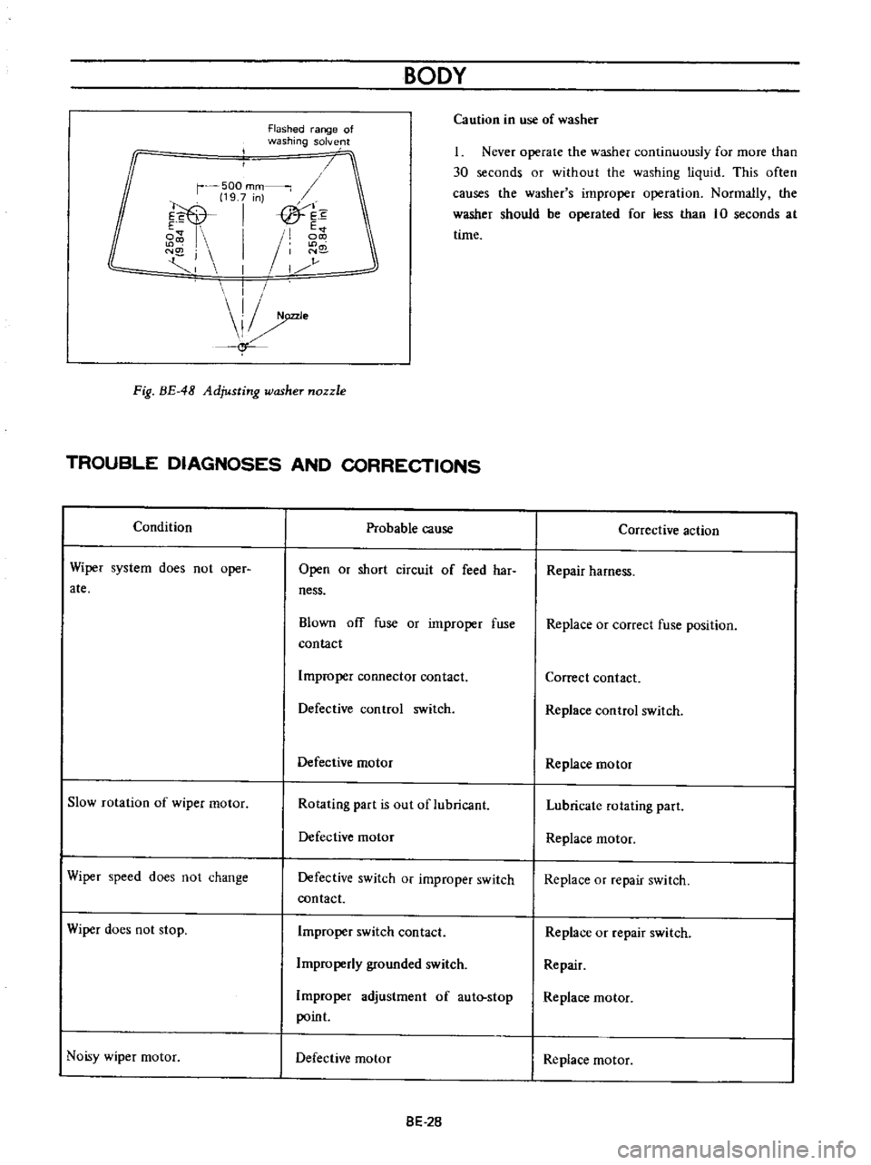
Flashed
range
of
washing
solve
lt
Ca
ution
in
use
of
washer
r
500
mm
19
7
n
E
I
fTh
e
i
E
I
I
N
j
1
N
I
1
r
j
I
I
e
f
1
Never
operate
the
washer
continuously
for
more
than
30
seconds
or
without
the
washing
liquid
This
often
causes
the
washer
s
improper
operation
Normally
the
washer
should
be
operated
for
less
than
10
seconds
at
time
Fig
BE
48
Adjusting
washer
nozzle
TROUBLE
DIAGNOSES
AND
CORRECTIONS
Condition
Probable
cause
Corrective
action
Wiper
system
does
not
oper
ate
Open
or
short
circuit
of
feed
har
ness
Repair
harness
Blown
ofT
fuse
or
improper
fuse
contact
Replace
or
correct
fuse
position
Improper
connector
contact
Correct
contact
Defective
control
switch
Replace
control
switch
Defective
motor
Replace
motor
Slow
rotation
of
wiper
motor
Rotating
part
is
out
of
lubricant
Lubricate
rotating
part
Defective
motor
Replace
rnotor
Wiper
speed
does
not
change
Defective
switch
or
improper
switch
contact
Replace
or
repair
switch
Wiper
does
not
stop
Improper
switch
contact
Replace
or
repair
switch
Irnproperly
grounded
switch
Repair
Improper
adjustment
of
aut
stop
point
Replace
motor
Noisy
wiper
motor
Defective
motor
Replace
motor
8E
2B
Page 319 of 513

ENGINE
Adjusting
throttle
opener
setting
engine
speed
1
Connect
servo
diaphragm
vacuum
hose
directly
to
intake
manifold
connector
without
laying
through
vacuum
control
valve
2
With
negative
pressure
vacuum
in
intake
manifold
servo
diaphragm
operates
and
thus
the
primary
throttle
valve
is
opened
When
servo
diaphragm
nor
mally
operates
engine
speed
rises
reaching
1
650
to
1
850
rpm
When
engine
speed
is
not
within
this
range
turn
adjusting
screw
as
necessary
See
Figure
ET
20
l
When
engine
speed
is
lower
than
the
prescribed
range
turn
adjusting
screw
clockwise
2
When
engine
speed
is
higher
than
the
prescribed
range
turn
adjusting
screw
counterclockwise
Upon
completion
of
the
adjustment
set
adjusting
screw
lock
nut
secwely
making
sure
that
engine
speed
is
in
the
prescribed
range
@
II
I
AdJustmg
screw
2
Lock
nut
Fig
ET
20
Servo
diaphragm
adjusting
screw
Servo
diaphragm
Servo
diaphragm
stroke
Link
EC015
3
Disconnect
servo
diaphragm
vacuum
hose
from
intake
manifold
and
connect
it
to
vacuum
control
valve
Connect
vacuum
hose
of
control
valve
to
intake
manifold
normal
piping
Racing
Place
shift
lever
in
neutral
for
MfT
or
N
or
p
for
AlT
Raise
engine
speed
up
to
approximately
3
000
rpm
under
no
load
and
close
throttle
valve
by
releasing
it
from
hand
Examine
engine
speed
to
see
whether
it
falls
to
idling
speed
I
When
engine
revolution
rails
to
idling
speed
See
Figure
ET
24
The
primary
throttle
valve
is
opened
by
the
link
connected
to
it
When
the
engine
speed
is
increased
to
approximately
3
000
rpm
and
lowered
natually
from
this
speed
changes
in
servo
diaphragm
link
stroke
manifold
vacuum
and
en
ine
speed
are
as
shown
in
Figure
ET
21
o
u
u
0
2
Se
o
diaphragm
link
stroke
I
u
2
Full
0
o
Intake
manifold
vacuum
u
c
E
c
O
3000
c
e
Engine
speed
2000
g
i
c
1000
T
j
Time
second
Fig
ET
21
Changes
in
servo
diaphragm
link
stroke
intake
manifold
vacuum
and
engine
speed
ET
14
Page 329 of 513

ENGINE
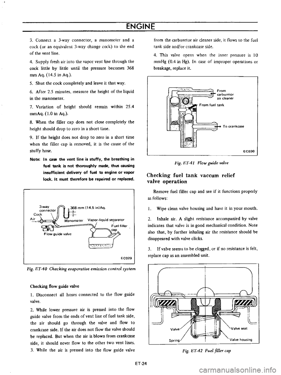
3
Connect
a
3
way
connector
a
manometer
and
a
cock
or
an
equivalent
3
way
change
cock
to
the
end
of
the
vent
line
4
Supply
fresh
air
into
the
vapor
vent
line
through
the
cock
little
by
little
until
the
pressure
becomes
368
mm
Aq
14
5
in
Aq
5
Shut
the
cock
completely
and
leave
it
that
way
6
After
2
5
minutes
measure
the
height
of
the
liquid
in
the
manometer
7
Variation
of
height
should
remain
within
254
mmAq
1
0
in
Aq
8
When
the
filler
cap
does
not
close
completely
the
height
should
drop
to
zero
in
a
short
time
9
If
the
height
does
not
drop
to
zero
in
a
short
time
when
the
filler
cap
is
removed
it
is
the
cause
of
the
stuffy
hose
Note
In
case
the
vent
line
is
stuffy
the
breathing
in
fuel
tank
is
not
thoroughly
made
thus
causing
insufficient
delivery
of
fuel
to
engine
or
vapor
lock
It
must
therefore
be
repaired
or
replaced
3
way
connector
Cock
Air
Manometer
Vapor
liquid
seearator
Flow
guide
valve
E
CQ29
Fig
ET
40
Checking
evaporative
emission
control
system
Checking
flow
guide
valve
I
Disconnect
all
hoses
connected
to
the
flow
guide
valve
2
While
lower
pressure
air
is
pressed
into
the
flow
guide
valve
from
the
ends
of
vent
line
of
fuel
tank
side
the
air
should
go
through
the
valve
and
flow
to
crankcase
side
If
the
air
does
not
flow
the
valve
should
be
replaced
But
when
the
air
is
blown
from
crankcase
side
it
should
never
flow
to
the
other
two
vent
lines
3
While
the
air
is
pressed
into
the
flow
guide
valve
from
the
carburetor
air
cleaner
side
it
flows
to
the
fuel
tank
side
and
or
crankcase
side
4
This
valve
opens
when
the
inner
pressure
is
10
mmHg
0
4
in
Hg
In
case
of
improper
operations
or
breakage
replace
it
From
carburetor
air
cleaner
From
fuel
tank
i
I
I
ti
i
i
1
1
i
To
ran
kcase
E
C030
Fig
ET
41
Flow
guide
valve
Checking
fuel
tank
vaCCUID
relief
valve
operation
Remove
fuel
filler
cap
and
see
if
it
functions
properly
as
follows
Wipe
clean
valve
housing
and
have
it
in
your
mouth
2
Inhale
air
A
slight
resistance
accompanied
by
valve
indicates
that
valve
is
in
good
mechanical
condition
Note
also
that
by
further
inhaling
air
the
resistance
should
be
disappeared
with
valve
clicks
3
If
valve
seems
to
be
clogged
or
if
no
resistance
is
felt
replace
cap
as
an
assembled
unit
T
1i
v
rUr1f
AlI
j
r
I
r
tLMJJl
rr
L
cc
11
J
v
II
4J
L
Valve
I
valve
seat
Spring
Valve
housing
Fig
ET
42
Fuel
filler
cap
ET
24
Page 417 of 513

ENGINE
ffi68
mmAq
14
5
mAq
3
way
connector
Cock
II
M
nam
e
Flow
guide
valve
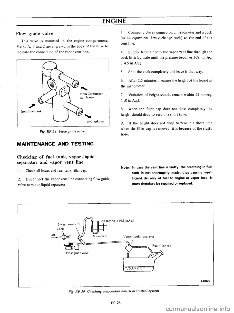
This
valve
is
mounted
in
the
engine
compartment
f
tHks
A
F
and
C
are
engraved
in
the
body
of
the
valve
to
indicate
the
connection
of
the
vapor
vent
line
l
l
1
from
Fuel
tank
to
Crankcase
Fig
EF
3B
Flow
guide
valve
MAINTENANCE
AND
TESTING
Checking
of
fuel
tank
vapor
liquid
separator
and
vapor
vent
line
Check
all
hoses
and
fuel
tank
filler
cap
2
Disconnect
the
vapor
vent
line
connecting
flow
guide
valve
to
vapor
liquid
separator
Flow
guide
valve
3
Connect
a
J
way
connector
a
manometer
and
a
l
ul
k
or
an
equivalent
3
wav
change
cock
to
the
end
of
the
vent
line
4
Supply
fresh
air
into
the
vapor
vent
line
through
the
cock
little
by
little
until
the
pressure
becomes
368
romAq
14
5
in
Aq
5
Shut
the
cock
completely
and
leave
it
that
way
6
After
2
5
minutes
measure
the
height
uf
the
liquid
in
the
manometer
7
Variation
of
height
should
remain
within
25
mmAq
1
0
in
Aq
8
When
the
filler
cap
does
not
close
completely
the
height
should
drop
to
zero
in
a
short
time
9
I
f
the
height
docs
not
drop
to
zero
in
a
short
time
when
the
filler
cap
is
removed
it
is
because
of
the
stuffy
hose
Note
In
case
the
vent
line
is
stuffy
the
breathing
in
fuel
tank
is
not
thoroughly
made
thus
causing
insuf
ficient
delivery
of
fuel
to
engine
or
vapor
lock
It
must
therefore
be
repaired
or
replaced
1
m
eparator
1
Fuel
filler
cap
Y
XI
EC029
Fig
EF
39
Checking
evaporative
emission
control
system
EF
26