1973 DATSUN B110 stop start
[x] Cancel search: stop startPage 7 of 513

AUTOMATIC
TRANSMISSION
Manual
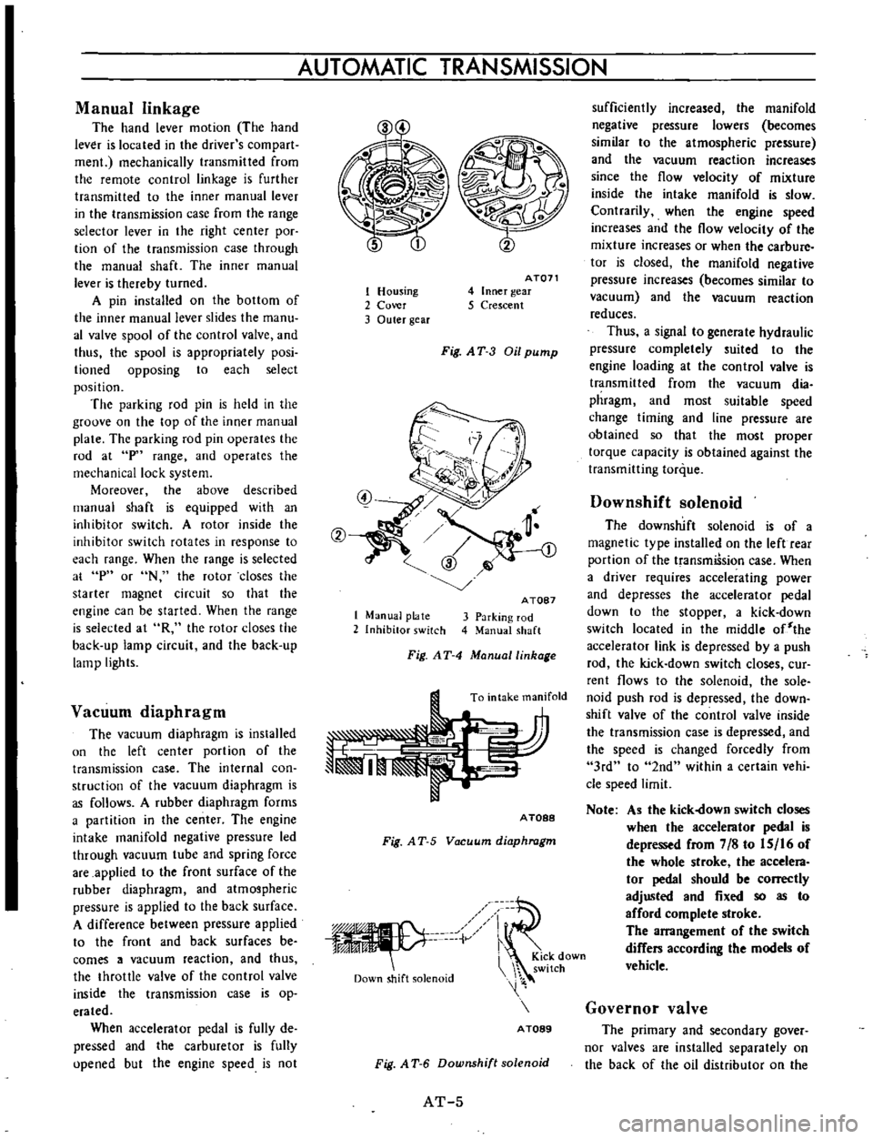
linkage
The
hand
lever
motion
The
hand
lever
is
located
in
the
driver
s
com
part
men
mechanically
transmitted
from
the
remote
control
linkage
is
further
transmitted
to
the
inner
manual
lever
in
the
transmission
case
from
the
range
selector
lever
in
the
right
center
poc
tion
of
the
transmission
case
through
the
manual
shaft
The
inner
manual
lever
is
thereby
turned
A
pin
installed
on
the
bottom
of
the
inner
manual
lever
slides
the
manu
al
valve
spool
of
the
control
valve
and
thus
the
spool
is
appropriately
posi
lioned
opposing
to
each
select
position
The
parking
rod
pin
is
held
in
the
groove
on
the
top
of
the
inner
manual
plate
The
parking
rod
pin
operates
the
rod
at
p
range
and
operates
the
mechanical
lock
system
Moreover
the
above
described
manual
shaft
is
equipped
with
an
inhibitor
switch
A
rotor
inside
the
inhibitor
switch
rotates
in
response
to
each
range
When
the
range
is
selected
at
p
or
N
the
rotor
closes
the
starter
magnet
circuit
so
that
the
engine
can
be
started
When
the
range
is
selected
at
R
the
rotor
closes
the
back
up
lamp
circuit
and
the
back
up
lamp
lights
Vacuum
diaphragm
The
vacuum
diaphragm
is
installed
un
the
left
center
portion
of
the
transmission
case
The
internal
con
struction
of
the
vacuum
diaphragm
is
as
follows
A
rubber
diaphragm
forms
a
partition
in
the
center
The
engine
intake
manifold
negative
pressure
led
through
vacuum
tube
and
spring
force
are
applied
to
the
front
surface
of
the
rubber
diaphragm
and
atmospheric
pressure
is
applied
to
the
back
surface
A
difference
between
pressure
applied
to
the
front
and
back
surfaces
be
comes
a
vacuum
reaction
and
thus
the
throttle
valve
of
the
control
valve
inside
the
transmission
case
is
op
erated
When
accelerator
pedal
is
fully
de
pressed
and
the
carburetor
is
fully
upened
but
the
engine
speed
is
not
1
Housing
2
Cover
3
Outer
gear
AT071
4
Inner
gear
5
Crescent
Fig
AT
3
Oil
pump
1
Manual
plate
2
Inhibitor
switch
A
TOB7
3
Parking
rod
4
Manual
shaft
Fig
AT
4
Manuallinhage
To
intake
manifold
A
TOBB
Fig
A
T
5
Vacuum
diaphragm
iV
Down
shift
solenoid
i
KiCk
down
switch
A
TOB9
Fig
A
T
6
Downshift
solenoid
AT
5
sufficiently
increased
the
manifold
negative
pressure
lowers
becomes
similar
to
the
atmospheric
pressure
and
the
vacuum
reaction
increases
since
the
flow
velocity
of
mixture
inside
the
intake
manifold
is
slow
Contrarily
when
the
engine
speed
increases
and
the
flow
velocity
of
the
mixture
increases
or
when
the
carbure
tor
is
closed
the
manifold
negative
pressure
increases
becomes
similar
to
vacuum
and
the
vacuum
reaction
reduces
Thus
a
signal
to
generate
hydraulic
pressure
completely
suited
to
the
engine
loading
at
the
control
valve
is
transmitted
from
the
vacuum
dia
phragm
and
most
suitable
speed
change
timing
and
line
pressure
are
obtained
so
that
the
most
proper
torque
capacity
is
obtained
against
the
transmitting
torque
Downshift
solenoid
The
downshift
solenoid
is
of
a
magnetic
type
installed
on
the
left
rear
portion
of
the
transmiSsion
case
When
a
driver
requires
accelerating
power
and
depresses
the
accelerator
pedal
down
to
the
stopper
a
kick
down
switch
located
in
the
middle
of
the
accelerator
link
is
depressed
by
a
push
rod
the
kick
down
switch
closes
cur
rent
flows
to
the
solenoid
the
sole
noid
push
rod
is
depressed
the
down
shift
valve
of
the
control
valve
inside
the
transmission
case
is
depressed
and
the
speed
is
changed
forcedly
from
3rd
to
2nd
within
a
certain
vehi
cle
speed
limit
Note
As
the
kick
own
switch
closes
when
the
accelerator
pedal
is
depressed
from
7
8
to
IS
16
of
the
whole
stroke
the
accelera
tor
pedal
should
be
correctly
adjusted
and
fixed
so
as
to
afford
complete
stroke
The
arrangement
of
the
switch
differs
according
the
models
of
vehicle
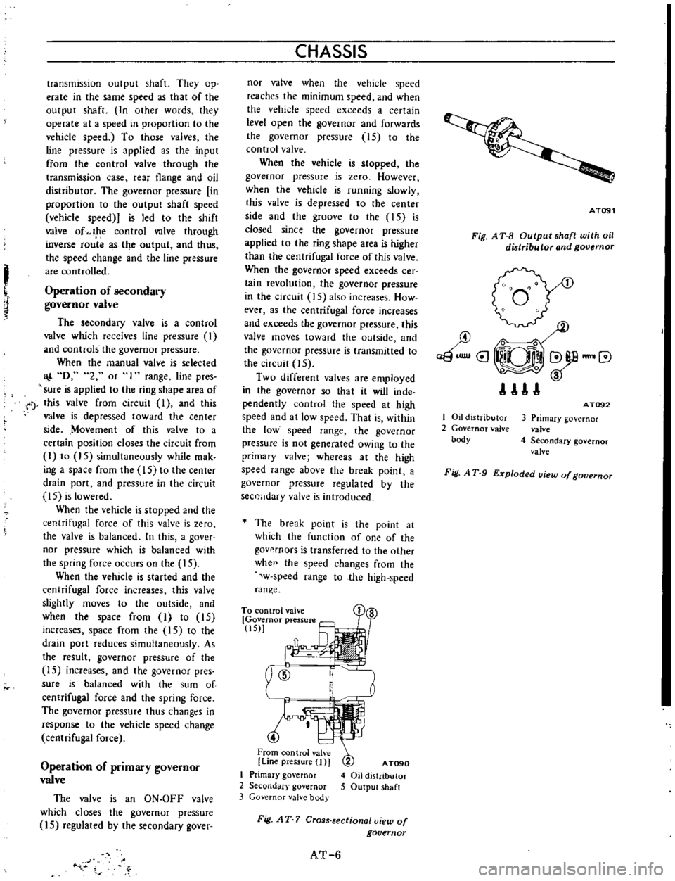
Governor
valve
The
primary
and
secondary
gover
nor
valves
are
installed
separately
on
the
back
of
the
oil
distributor
on
the
Page 8 of 513

I
transmission
output
shaft
They
op
erate
in
the
same
speed
as
that
of
the
output
shaft
In
other
wotds
they
operate
at
a
speed
in
proportion
to
the
vehicle
speed
To
those
valves
the
line
pressure
is
applied
as
the
input
ftom
the
control
valve
through
the
transmission
case
rear
flange
and
oil
distributor
The
governor
pressure
in
proportion
to
the
output
shaft
speed
vehicle
speed
is
led
to
the
shift
valve
of
the
control
valve
through
inverse
rou
te
as
the
output
and
thus
the
speed
change
and
the
line
pressure
are
controlled
Operation
of
secondary
governor
valve
The
secondary
valve
is
a
control
valve
which
receives
line
pressure
I
and
controls
the
governor
pressure
When
the
manual
valve
is
selected
D
2
or
1
range
line
pres
sure
is
applied
to
the
ring
shape
area
of
f
this
valve
from
circuit
I
and
this
valve
is
depressed
toward
the
center
side
Movement
of
this
valve
to
a
certain
position
closes
the
circuit
from
I
to
15
simultaneously
while
mak
ing
a
space
from
the
15
to
the
center
drain
port
and
pressure
in
the
circuit
IS
is
lowered
When
the
vehicle
is
stopped
and
the
centrifugal
force
of
this
valve
is
zero
the
valve
is
balanced
In
this
a
gover
nor
pressure
which
is
balanced
with
the
spring
force
occurs
on
the
15
When
the
vehicle
is
started
and
the
centrifugal
force
increases
this
valve
slightly
moves
to
the
outside
and
when
the
space
from
I
to
15
increases
space
from
the
15
to
the
drain
port
reduces
simultaneously
As
the
result
governor
pressure
of
the
15
increases
and
the
governor
pres
sure
is
balanced
with
the
sum
of
centrifugal
force
and
the
spring
force
The
governor
pressure
thus
changt
s
in
response
to
the
vehicle
speed
change
centrifugal
force
Operation
of
primary
governor
valve
The
valve
is
an
ON
OFF
valve
which
closes
the
governor
pressure
15
regulated
by
the
secondary
gover
CHASSIS
nor
valve
when
the
vehicle
speed
reaches
the
minimum
speed
and
when
the
vehicle
speed
exceeds
a
certain
level
open
the
governor
and
forwards
the
governor
pressure
15
to
the
control
valve
When
the
vehicle
is
stopped
the
governor
pressure
is
zero
However
when
the
vehicle
is
running
slowly
this
valve
is
depressed
to
the
center
side
and
the
groove
to
the
IS
is
closed
since
the
governor
pressure
applied
to
the
ring
shape
area
is
higher
than
the
centrifugal
force
of
this
valve
When
the
governor
speed
exceeds
cer
tain
revolution
the
governor
pressure
in
the
circuit
15
also
increases
How
ever
as
the
centrifugal
force
increases
and
exceeds
the
governor
pressure
this
valve
moves
toward
the
outside
and
the
governor
pressure
is
transmitted
to
the
circuit
15
Two
different
valves
are
employed
in
the
governor
so
that
it
will
inde
pendently
control
the
speed
at
high
speed
and
at
low
speed
That
is
within
the
low
speed
range
the
governor
pressure
is
not
generated
owing
to
the
primary
valve
whereas
at
the
high
speed
range
above
the
break
point
a
governor
pressure
regula
ted
by
the
sec0Hdary
valve
is
introduced
The
break
point
is
the
point
at
which
the
function
of
one
of
the
govp
rnors
is
transferred
to
the
other
whee
the
speed
changes
from
the
w
speed
range
to
the
high
speed
range
To
con
trol
valve
Governor
pressure
tiS
y
ID
t
4
From
control
valve
Line
pressure
I
J
I
Primary
governor
2
Secondar
governor
3
Governor
valve
body
AT090
4
Oil
distributor
5
Output
shaft
Fig
AT
7
Cross
sectional
view
of
governor
AT
6
AT091
Fig
A
T
B
Output
shaft
with
oil
distributor
and
governor
I
Oil
distributor
2
Governor
valve
body
AT092
3
Primary
governor
valve
4
Secondary
governor
valve
Fig
A
T
9
Exploded
uiew
of
gouernor
Page 56 of 513

and
band
are
adversely
af
fected
Sufficient
cooling
time
should
be
given
between
each
test
for
the
four
ranges
0
2
I
and
R
Judgement
I
High
stall
revolution
more
than
standard
revolution
If
the
engine
revolution
in
staU
condition
is
higher
than
the
standard
values
it
indicates
that
one
or
more
clutches
in
the
transmission
are
slip
ping
and
therefore
nO
further
test
is
required
For
the
following
abnormalities
the
respective
causes
3re
presumed
High
rpm
in
all
ranges
Low
line
pre
ure
High
rpm
in
D
2
and
I
and
normal
rpm
in
R
Rear
clutch
slipping
High
pm
in
D
and
2
and
normal
rpm
in
lOne
way
clutch
slipping
High
rpm
in
R
only
Front
clutch
or
low
and
reverse
brake
slipping
To
determine
which
is
slipping
either
front
clutch
or
low
and
reverse
brake
a
road
test
is
needed
If
while
coasting
after
starting
with
the
lever
in
I
range
engine
braking
does
not
work
properly
it
is
deter
mined
the
low
and
reverse
brake
is
slipping
Otherwise
the
front
clutch
is
slipping
The
slipping
of
the
band
brake
is
difficult
to
ascertain
However
if
it
occurs
with
the
lever
in
2
range
the
enigne
revolution
increases
up
to
the
same
level
as
in
1st
speed
and
therefore
it
can
be
found
out
by
careful
observation
It
is
impossible
to
check
it
in
the
stall
test
Z
Standard
stall
revolution
If
the
enigne
revolution
in
stall
condition
is
within
the
standard
values
the
control
elements
are
nor
mally
operating
in
the
ranges
0
2
I
and
R
Also
the
engine
and
one
way
clutch
of
the
torque
converter
are
normal
in
perfonnance
and
operation
The
one
way
clutch
of
the
torque
Gear
shift
Propeller
shaft
rpm
D
D
1
840
to
2
340
D
DJ
3
340
to
3
840
DJ
D
3
460
to
2
960
D
0
1
790
to
1
290
D
D
330
to
830
D
OJ
l
720
to
2
220
DJ
D2
or
1
350
to
850
DJ
D
D
0
700
Max
I
I
1
860
to
1
360
CHASSIS
converter
however
sometimes
sticks
This
should
be
determined
in
the
road
test
3
Low
stall
revolution
less
than
standard
revolution
If
the
engine
revolution
in
stall
condition
is
lower
than
the
standard
values
it
indicates
that
the
engine
is
in
abnormal
condition
or
the
torque
con
verter
s
one
way
clutch
is
slipping
4
Other
I
If
the
accelerating
performance
is
poor
until
vehicle
speed
of
approxi
mately
50
km
h
30
MPH
is
attained
and
then
normal
beyond
that
speed
it
can
be
judged
that
the
torque
con
verter
s
one
way
dutch
is
slipping
2
If
the
torque
converter
s
one
way
clutch
sticks
vehicle
speed
can
not
exceed
approximately
80
km
h
Car
speed
at
gear
shift
Throttle
opening
mmHg
Kick
down
0
Half
throttle
200
Full
throttle
0
Minimum
throttle
450
I
50
MPH
in
the
road
test
In
such
a
case
the
torque
converter
oH
tempera
ture
rises
up
abnormally
and
s
o
s
pecial
care
is
required
13
If
the
transmission
does
not
operate
properly
in
all
vehicle
speeds
it
indicates
poor
engine
perfonnance
ROAD
TEST
An
accurate
knowledge
of
the
auto
matic
transmission
is
prerequisite
to
its
exact
diagnosis
by
a
road
test
It
is
recommended
to
prepare
a
diagnosis
guide
chart
in
which
are
written
the
standard
vehicle
speeds
for
each
stage
of
the
up
and
down
shiftings
Measured
vehicle
speeds
are
to
be
filled
in
the
adjoining
column
in
each
testing
Also
it
is
advisable
to
mount
a
stopper
for
positioning
the
throttle
opening
I
I
1
860
to
1
360
I
Reduce
the
speed
by
shifting
to
range
from
D
range
output
shaft
2
000
rpm
Note
Car
speed
can
be
calculated
by
the
following
fonnula
2
x
7r
x
r
x
Npx
60
v
RF
X
1
000
where
V
Car
speed
km
h
Np
Propeller
shaft
revolution
rpm
RF
Final
gear
ratio
r
Tire
effective
radius
m
11
The
ratio
of
circumference
of
a
circle
to
its
diameter
3
14
AT
52
Page 261 of 513

The
lamp
does
not
go
out
when
the
engine
is
started
Faulty
charging
system
BODY
Inspect
the
charging
system
WINDSHIELD
WIPER
AND
WASHER
Description
Wiper
motor
replacement
Wiper
blade
operating
range
CONTENTS
BE
26
BE
27
BE
27
Description
The
windshield
wipers
consist
of
wiper
motor
link
mechanism
wiper
arms
and
blades
The
wiper
motor
unit
consists
of
a
motor
and
auto
stop
mechanism
The
wiper
rnotor
is
of
a
2
speed
type
When
the
wiper
switch
knob
is
pulled
to
the
I
st
step
the
windshield
wipers
operate
at
low
speed
and
when
pulled
to
the
2nd
step
operate
at
high
speed
The
wiper
motor
unit
is
located
on
the
cowl
dash
in
BATTERY
Cl
WIPER
MOTOR
rrQ
J
WASHER
MOTOR
IB
ILRI
L
CJ
LA
t
Y
I
Ll
j
IBI
1
f
I
LW
I
Wiper
washer
switch
replacement
Washer
nozzle
adjustment
TROUBLE
OIAGNOSES
ANO
CORRECTIONS
BE
27
BE
27
BE
28
the
engine
compartment
and
the
link
mechanism
is
located
behind
the
instrument
panel
The
electrically
operated
windshield
washer
consists
of
washing
fluid
lank
with
rnotor
and
pump
washer
nozzles
and
vinyl
tube
used
to
connect
those
compo
nents
The
windshield
washer
switch
is
combined
with
the
windshield
wiper
switch
to
a
single
unit
When
operating
the
washer
twist
the
switch
knob
IG
FUSE
W
v
l
i
f
WIPER
SWITCH
10FFI
I
2
I
TWIST
I
y
ILl
I
b
I
J
6
I
BLII
Fig
BE
43
Circuit
diagram
for
windshield
wiper
washer
system
BE
26
Page 268 of 513

BODY
ELECTRICAL
Distributor
Secure
ground
of
ignition
coil
Secure
contact
of
carbon
electric
pole
and
rotor
Eliminate
excessive
tip
on
the
rotor
pole
or
cap
pole
by
scrubbing
with
a
screwdriver
Check
stagger
between
rotor
and
stator
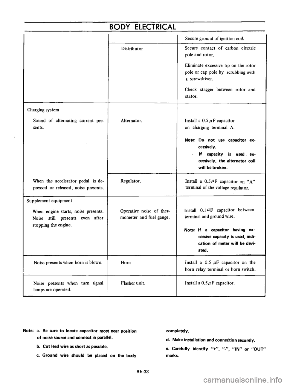
Charging
system
Sound
of
alternating
current
pre
sents
Alternator
Install
a
0
5
l
F
capacitor
on
charging
terminal
A
Note
Do
not
use
capacitor
ex
cessively
If
capacity
is
used
ex
cessively
the
alternator
coil
will
be
broken
When
the
accelerator
pedal
is
de
pressed
or
released
noise
presents
Regulator
Install
a
0
5
l
F
capacitor
on
A
terrninal
of
the
voltage
regulator
Supplement
equipment
When
engine
starts
noise
presents
Noise
still
presents
even
after
stopping
the
engine
Operative
noise
of
ther
rnometer
and
fuel
gauge
Install
0
1
l
F
capacitor
between
terminal
and
ground
wire
Note
If
a
capacitor
having
ex
cessive
capacity
is
used
indi
cation
of
meter
will
be
devi
ated
Noise
presents
when
horn
is
blown
Horn
Install
a
0
5
IF
capacitor
on
the
horn
relay
terminal
or
horn
switch
Noise
presents
when
turn
signal
lamps
are
operated
Flasher
unit
Install
a
0
5
l
F
capacitor
Note
a
Be
sure
to
locate
capacitor
most
near
position
of
noise
source
and
connect
in
parallel
completely
d
Make
installation
and
conneCtion
securely
b
Cut
lead
wire
as
short
as
possible
c
Ground
wire
should
be
placed
on
the
body
e
Carefully
identify
marks
IN
or
OUT
BE
33
Page 306 of 513

EMISSION
CONTROL
AND
TUNE
UP
EMISSION
CONTROL
SYSTEM
AN
D
ENGINE
TUNE
UP
CONTENTS
BASIC
MECHANICAL
SYSTEM
ET
Checking
and
adjusting
dash
pot
Adjusting
intake
and
exhaust
valve
automatic
transmission
model
only
ET
9
clearances
ET
1
Checking
carburetor
return
spring
ET
9
Checking
and
adjustin9
drive
belt
ET
2
Checking
choke
mechanism
choke
valve
Retightening
cylinder
head
bolts
manifold
and
linkagel
ET
9
nuts
and
carburetor
securing
nuts
ET
2
Checking
anti
dieseling
solenoid
ET
9
Checking
engine
oil
ET
2
Replacing
fuel
filter
ET
10
Replacing
oil
filter
ET
3
Checking
fuel
lines
hoses
pipings
Changing
engine
coolant
L
L
C
ET
3
connections
etc
ET10
Checking
cooling
system
hoses
and
THROTTLE
OPENER
CONTROL
SYSTEM
ET
10
connections
ET
4
Checking
and
adjusting
throttle
opener
ET
13
Checking
vacuum
fittings
hoses
and
TRANSMISSION
CONTROLLED
VACUUM
connections
ET
4
ADVANCE
SYSTEM
ET
17
Checking
engine
compression
ET
4
Checking
electrical
advance
control
system
ET
19
Checking
exhaust
manifold
heat
control
AUTOMATIC
TEMPERATURE
CONTROL
AIR
valve
ET
5
CLEANER
A
T
C
AIR
CLEANER
ET
20
IGNITION
AND
FUEL
SYSTEM
ET
5
Replacing
carburetor
air
cleaner
filter
ET
20
Checking
battery
ET
5
Checking
hot
air
control
valve
ET
20
Checking
and
adjusting
ignition
timing
ET
5
CRANKCASE
EMISSION
CONTROL
Checking
or
replacing
distributor
breaker
SYSTEM
ET
22
point
condenser
and
spark
plugs
ET
6
Checking
or
replacing
PCV
valve
ET
23
Checking
distributor
ignition
wiring
and
Checking
ventilation
hoses
ET
23
ignition
coil
ET
7
EVAPORATIVE
EMISSION
CONTROL
Checking
distributor
cap
and
rotor
ET
7
SYSTEM
ET
23
Adjusting
carburetor
id
Ie
rpm
and
Checking
engine
compartment
hose
mixture
ratio
ET
8
connections
and
fuel
vapor
control
valves
ET
23
Checking
fuel
tank
vacuum
relief
valve
operation
ET
24
BASIC
MECHANICAL
SYSTEM
1
Start
engine
and
run
it
until
it
is
heated
to
operating
temperature
or
at
least
more
than
800C
I760F
of
engine
oil
temperature
then
stop
engine
Adjusting
intake
and
exhaust
valve
clearances
Valve
clearance
adjustment
should
be
made
while
engine
is
stationary
To
adjust
proceed
as
follows
2
Rotate
crankshaft
to
bring
No
1
cylinder
in
top
dead
center
on
its
compression
stroke
3
Remove
valve
rocker
cover
to
gain
access
to
valve
ET
1
Page 313 of 513

ENGINE
Adjusting
carburetor
idle
rpm
mixture
ratio
Idle
mixture
adjustment
requires
the
use
of
a
CO
meter
When
preparing
to
adjust
idle
mixture
it
is
essential
to
have
the
meter
thoroughly
warmed
and
calibrated
Warm
up
the
engine
sufficiently
2
Continue
engine
operation
for
one
minute
under
idling
speed
3
Adjust
throttle
adjusting
screw
so
that
engine
speed
is
800
rpm
in
NO
position
for
automatic
transmission
4
Check
ignition
timing
if
necessary
adjust
it
to
the
specifications
Ignition
timing
SO
800
rpm
S
Adjust
idle
adjusting
screw
so
that
CO
percentage
is
1
5
t
O
S
6
Repeat
the
adjustments
as
described
in
steps
3
and
S
above
so
that
CO
percentage
is
I
i
t
O
S
at
800
rpm
Cautions
a
On
automatic
transmission
equipped
model
check
must
be
done
in
the
0
position
Be
sure
to
apply
parking
brake
and
to
lock
both
front
and
rear
wheels
with
wheel
chocks
b
Hold
brake
pedal
while
stepping
down
on
accelerator
pedal
Otherwise
car
will
rush
out
dangerously
7
On
automatic
transmission
equipped
model
make
sure
that
the
adjustment
has
been
made
with
the
selector
lever
in
N
position
And
then
check
the
specifications
with
the
lever
in
D
position
Insure
that
CO
percent
and
idle
speed
are
as
follows
Idle
rpm
CO
percentage
with
lever
in
D
position
6S0
I
S
t
O
S
If
necessary
adjust
by
progressively
turning
throttle
adjusting
screw
and
idle
adjusting
screw
until
correct
adjustments
are
made
Notes
a
Do
not
attempt
to
screw
down
the
idle
adjusting
screw
completely
to
avoid
damage
to
the
tip
which
will
tend
to
cause
malfunctions
b
After
idle
adjustment
has
been
made
shift
the
lever
to
N
or
p
position
for
automatic
transmission
c
Remove
wheel
chocks
before
starting
the
car
Throttle
adjusting
screw
Idle
adjust
ing
screw
3
Idle
limitter
cap
4
Stopper
Fig
ET
13
Throttle
adjusting
screw
and
idle
adjusting
screw
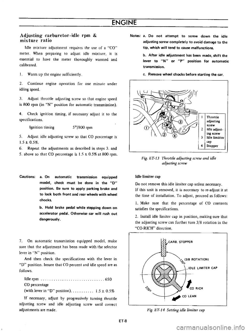
Idle
limiter
cap
Do
not
remove
this
idle
limiter
cap
unless
necessary
If
this
unit
is
removed
it
is
necessary
to
re
adjust
it
at
the
time
of
installation
To
adjust
proceed
as
follows
L
Make
sure
that
the
percentage
of
CO
contents
satisfies
the
specifications
2
Install
idle
limiter
cap
in
position
making
sure
that
the
adjusting
screw
can
further
turn
3
8
rotation
in
the
CO
RICH
direction
CARB
STOPPER
J
Z
3
8
ROTATION
0
IDLE
LIMITER
CAP
0
to
RICH
CO
LEAN
Fig
l
T
14
Setting
idle
limiter
cap
ET
8
Page 314 of 513

EMISSION
CONTROL
AND
TUNE
UP
Checking
and
adjusting
dash
pot
automatic
transmission
model
only
Check
operation
of
dash
pot
It
should
not
be
cracked
or
bound
It
is
also
essential
to
check
to
be
certain
that
it
is
in
correct
adjustment
L
Check
to
be
sure
that
dash
pot
contacts
stopper
lever
when
engine
speed
reaches
1
900
to
2
000
rpm
2
Engine
should
be
slowed
down
from
3
000
to
1
000
rpm
within
a
few
seconds
Readjust
dash
pot
or
replace
it
with
a
new
one
if
it
fails
to
meet
the
above
conditions
Checking
carburetor
return
spring
Check
throttle
return
spring
for
sign
of
damage
wear
or
squareness
Discard
spring
if
found
with
any
of
above
excessively
beyond
use
Checking
choke
mechanism
choke
valve
and
linkage
1
Check
choke
valve
and
mechanism
for
free
operation
and
clean
or
replace
if
necessary
A
binding
condition
may
have
developed
from
petro
leum
gum
for
motion
on
choke
shaft
or
from
damage
2
Check
bimetal
cover
setting
position
The
index
mark
of
bimetal
cover
is
usually
aligned
at
the
middle
point
of
the
scale
Note
When
somewhat
over
choked
turn
bimetal
caver
clockwise
slightly
3
Prior
to
starting
check
to
be
sure
that
choke
valve
closes
automatically
when
pressing
down
on
accelerator
pedal
Should
it
fail
to
close
automatically
the
likelihood
is
that
fast
idle
cam
is
out
of
proper
adjustment
or
that
bimetal
is
not
properly
adjusted
calling
for
adjustment
Refer
to
Carburetor
in
Section
EF
Page
EF
15
Checking
anti
dieseling
solenoid
If
engine
will
not
stop
when
ignition
switch
is
turned
off
this
indicates
a
striking
closed
solenoid
valve
shutting
off
supply
of
fuel
to
engine
If
harness
is
in
good
condition
replace
solenoid
as
a
unit
To
replace
proceed
as
follows
Removal
and
installation
of
anti
dieseling
solenoid
Removal
Solenoid
is
cemented
at
factory
Use
special
tool
STl
91
50000
to
remove
a
solenoid
When
this
tool
is
not
effective
use
a
pair
of
pliers
to
loosen
body
out
of
position
lnstalltion
I
Before
installing
a
solenoid
it
is
essential
to
clean
all
threaded
parts
of
carburetor
and
solenoid
Supply
screws
in
holes
and
turn
them
in
two
or
three
pitches
2
First
without
disturbing
the
above
setting
coat
all
exposed
threads
with
adhensive
the
Stud
Lock
of
LOCTlTE
or
equivalent
Then
torque
screws
to
35
to
55
kg
cm
30
to
48
in
lb
using
a
special
tool
STl9150000
After
installing
anti
dieseling
solenoid
leave
the
carbu
retor
more
than
12
hours
without
operation
3
After
replacement
is
over
start
engine
and
check
to
be
sure
that
fuel
is
not
leaking
and
that
anti
dieseling
solenoid
is
in
good
condition
Notes
a
Do
not
allow
adhesive
getting
on
valve
Failure
to
follow
this
caution
would
result
in
improper
valve
performance
or
clogged
fuel
passage
b
I
n
installing
valve
use
caution
not
to
hold
body
directly
Instead
use
special
tool
tighten
ing
nuts
as
required
ET
9