1973 DATSUN B110 ECO mode
[x] Cancel search: ECO modePage 4 of 513
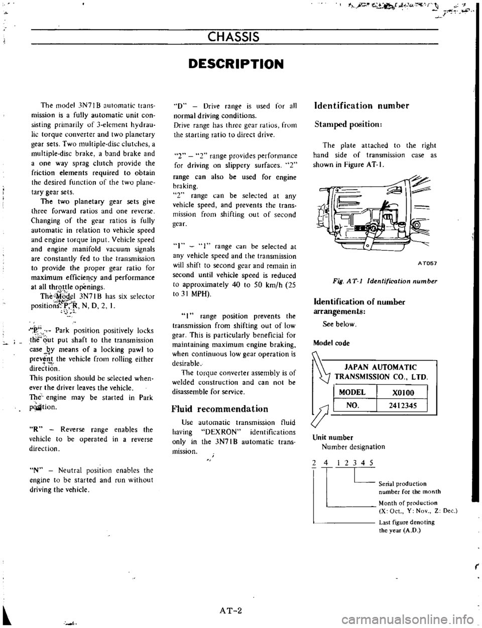
The
model
3N71
B
automatic
trans
mission
is
a
fully
automatic
unit
con
sisting
primarily
of
element
hydrau
lic
torque
converter
and
two
planetary
gear
sets
Two
multiple
disc
clutches
a
muItiple
disc
brake
a
band
brake
and
a
one
way
sprag
clutch
provide
the
friction
elements
required
to
obtain
the
desired
function
of
the
two
plane
tary
gear
sets
The
two
planetary
gear
sets
give
three
forward
ratios
and
one
reverse
Changing
of
the
gear
ratios
is
fully
automatic
in
relation
to
vehicle
speed
and
engine
torque
input
Vehicle
speed
and
engine
manifold
vacuum
signals
are
constantly
fed
to
the
transmission
to
provide
the
proper
gear
ratio
for
maximum
efficieq
cy
and
performance
at
all
thrqttIe
openings
The
iMiij
l
3N7I
B
has
six
selector
position
f
P
R
N
D
2
1
k
Park
position
positively
locks
the
c
ut
put
shaft
to
the
transmission
case
RY
means
of
a
locking
pawl
to
prev
nt
the
vehicle
from
rolling
either
direction
This
position
should
be
selected
when
ever
the
driver
leaves
the
vehicle
The
engine
may
be
started
in
Park
pQlition
OR
Reverse
range
enables
the
vehicle
to
be
operated
in
a
reverse
direction
N
Neutral
posItion
enables
the
engine
to
be
started
and
run
without
driving
the
vehicle
CHASSIS
DESCRIPTION
D
Drive
range
is
used
for
all
normal
driving
conditions
Drive
range
has
three
gear
ratios
frum
the
starting
ratio
to
direct
drive
2
2
range
provides
performance
for
driving
on
slippery
surfaces
2
range
can
also
be
used
for
engine
braking
2
range
can
be
selected
at
any
vehicle
speed
and
prevents
the
trans
mission
from
shifting
out
of
second
gear
I
range
can
be
selected
at
any
vehicle
speed
and
the
transmission
will
shift
to
second
gear
and
remain
in
second
until
vehide
speed
is
reduced
to
approximately
40
to
50
kmfh
25
to
31
MPH
I
range
position
prevents
the
transmission
from
shifting
out
of
low
gear
This
is
particularly
beneficial
for
maintaining
maximum
engine
braking
when
continuous
low
gear
operation
is
desirable
The
torque
converter
assembly
is
of
welded
construction
and
can
not
be
disassemble
for
service
Fluid
recommendation
Use
having
only
in
mission
automatic
transmission
fluid
DEXRON
identifications
the
3N7I
B
automatic
trans
AT
2
IA
e
l
csr
4o
J
r
s
Identification
number
Stamped
position
The
plate
attached
to
the
right
hand
side
of
transmission
case
as
shown
in
Figure
AT
I
ii
II
r
4
1
r
I
to
i
AT057
Fig
AT
1
Identification
number
Identification
of
number
arrangements
See
below
Model
code
JAPAN
AUTOMATIC
Z
TRANSMISSION
CO
LTD
I
MODEL
XOIOO
J
I
NO
2412345
Unit
number
Number
designation
2
4
2
3
4
5
L
Seriat
production
number
for
the
month
Month
of
production
X
Oct
Y
Nov
Z
Dec
Last
figure
denoting
the
year
A
D
r
Page 7 of 513
AUTOMATIC
TRANSMISSION
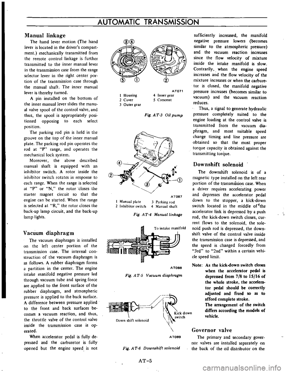
Manual
linkage
The
hand
lever
motion
The
hand
lever
is
located
in
the
driver
s
com
part
men
mechanically
transmitted
from
the
remote
control
linkage
is
further
transmitted
to
the
inner
manual
lever
in
the
transmission
case
from
the
range
selector
lever
in
the
right
center
poc
tion
of
the
transmission
case
through
the
manual
shaft
The
inner
manual
lever
is
thereby
turned
A
pin
installed
on
the
bottom
of
the
inner
manual
lever
slides
the
manu
al
valve
spool
of
the
control
valve
and
thus
the
spool
is
appropriately
posi
lioned
opposing
to
each
select
position
The
parking
rod
pin
is
held
in
the
groove
on
the
top
of
the
inner
manual
plate
The
parking
rod
pin
operates
the
rod
at
p
range
and
operates
the
mechanical
lock
system
Moreover
the
above
described
manual
shaft
is
equipped
with
an
inhibitor
switch
A
rotor
inside
the
inhibitor
switch
rotates
in
response
to
each
range
When
the
range
is
selected
at
p
or
N
the
rotor
closes
the
starter
magnet
circuit
so
that
the
engine
can
be
started
When
the
range
is
selected
at
R
the
rotor
closes
the
back
up
lamp
circuit
and
the
back
up
lamp
lights
Vacuum
diaphragm
The
vacuum
diaphragm
is
installed
un
the
left
center
portion
of
the
transmission
case
The
internal
con
struction
of
the
vacuum
diaphragm
is
as
follows
A
rubber
diaphragm
forms
a
partition
in
the
center
The
engine
intake
manifold
negative
pressure
led
through
vacuum
tube
and
spring
force
are
applied
to
the
front
surface
of
the
rubber
diaphragm
and
atmospheric
pressure
is
applied
to
the
back
surface
A
difference
between
pressure
applied
to
the
front
and
back
surfaces
be
comes
a
vacuum
reaction
and
thus
the
throttle
valve
of
the
control
valve
inside
the
transmission
case
is
op
erated
When
accelerator
pedal
is
fully
de
pressed
and
the
carburetor
is
fully
upened
but
the
engine
speed
is
not
1
Housing
2
Cover
3
Outer
gear
AT071
4
Inner
gear
5
Crescent
Fig
AT
3
Oil
pump
1
Manual
plate
2
Inhibitor
switch
A
TOB7
3
Parking
rod
4
Manual
shaft
Fig
AT
4
Manuallinhage
To
intake
manifold
A
TOBB
Fig
A
T
5
Vacuum
diaphragm
iV
Down
shift
solenoid
i
KiCk
down
switch
A
TOB9
Fig
A
T
6
Downshift
solenoid
AT
5
sufficiently
increased
the
manifold
negative
pressure
lowers
becomes
similar
to
the
atmospheric
pressure
and
the
vacuum
reaction
increases
since
the
flow
velocity
of
mixture
inside
the
intake
manifold
is
slow
Contrarily
when
the
engine
speed
increases
and
the
flow
velocity
of
the
mixture
increases
or
when
the
carbure
tor
is
closed
the
manifold
negative
pressure
increases
becomes
similar
to
vacuum
and
the
vacuum
reaction
reduces
Thus
a
signal
to
generate
hydraulic
pressure
completely
suited
to
the
engine
loading
at
the
control
valve
is
transmitted
from
the
vacuum
dia
phragm
and
most
suitable
speed
change
timing
and
line
pressure
are
obtained
so
that
the
most
proper
torque
capacity
is
obtained
against
the
transmitting
torque
Downshift
solenoid
The
downshift
solenoid
is
of
a
magnetic
type
installed
on
the
left
rear
portion
of
the
transmiSsion
case
When
a
driver
requires
accelerating
power
and
depresses
the
accelerator
pedal
down
to
the
stopper
a
kick
down
switch
located
in
the
middle
of
the
accelerator
link
is
depressed
by
a
push
rod
the
kick
down
switch
closes
cur
rent
flows
to
the
solenoid
the
sole
noid
push
rod
is
depressed
the
down
shift
valve
of
the
control
valve
inside
the
transmission
case
is
depressed
and
the
speed
is
changed
forcedly
from
3rd
to
2nd
within
a
certain
vehi
cle
speed
limit
Note
As
the
kick
own
switch
closes
when
the
accelerator
pedal
is
depressed
from
7
8
to
IS
16
of
the
whole
stroke
the
accelera
tor
pedal
should
be
correctly
adjusted
and
fixed
so
as
to
afford
complete
stroke
The
arrangement
of
the
switch
differs
according
the
models
of
vehicle
Governor
valve
The
primary
and
secondary
gover
nor
valves
are
installed
separately
on
the
back
of
the
oil
distributor
on
the
Page 48 of 513
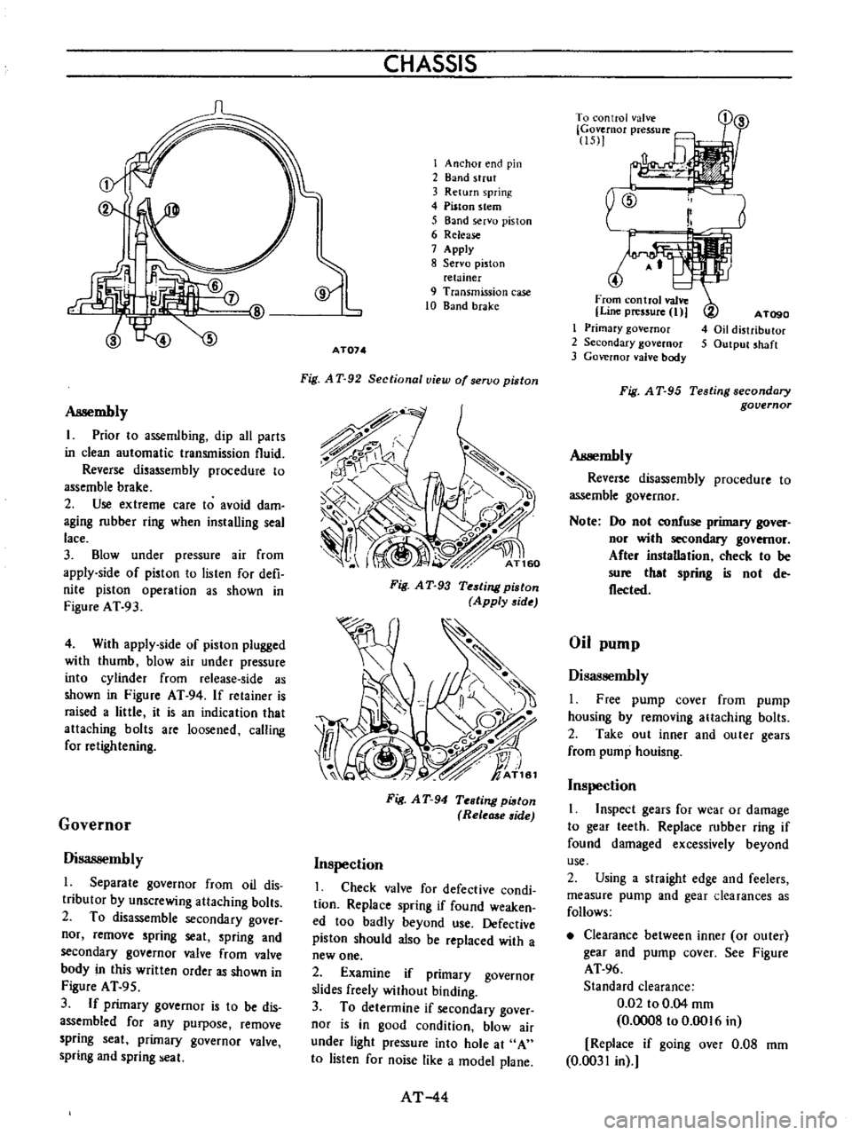
Assembly
I
Prior
10
assemlbing
dip
all
parts
in
clean
automatic
transmission
fluid
Reverse
disassembly
procedure
to
assemble
brake
2
Use
extreme
care
to
avoid
dam
aging
rubber
ring
when
installing
seal
lace
3
Blow
under
pressure
air
from
apply
side
of
piston
to
lislen
for
defi
nite
piston
operation
as
shown
in
Figure
AT
93
4
With
appIy
side
of
piston
plugged
with
thumb
blow
air
under
pressure
into
cylinder
from
release
side
as
shown
in
Figure
AT
94
If
retainer
is
raised
a
little
it
is
an
indication
that
attaching
bolts
are
loosened
calling
for
retightening
Governor
Disassembly
l
Separate
governor
from
oil
dis
tributor
by
unscrewing
attaching
bolts
2
To
disassemble
secondary
gover
nor
remove
spring
seat
spring
and
secondary
governor
valve
from
valve
body
in
this
written
order
as
shown
in
Figure
AT
95
3
If
primary
governor
is
to
be
dis
assembled
for
any
purpose
remove
spring
seat
primary
governor
valve
spring
and
spring
eal
CHASSIS
I
Anchor
end
pin
2
Band
strut
3
Return
spring
4
Piston
stem
5
Band
servo
piston
6
Release
7
Apply
8
Servo
piston
relainer
9
Transmission
case
10
Band
brake
AT074
Fig
A
T
92
Sectional
view
of
servo
piston
Fig
A
T
93
Testing
piston
Apply
side
Fig
A
T
94
Testing
pi8ton
Rele
side
Inspection
I
Check
valve
for
defective
condi
tion
Replace
spring
if
found
weaken
ed
too
badly
beyond
use
Defective
piston
should
also
be
replaced
with
a
new
one
2
Examine
if
primary
governor
slides
freely
without
binding
3
To
determine
if
secondary
gover
nor
is
in
good
condition
blow
air
under
light
pressure
into
hole
at
A
to
listen
for
noise
like
a
model
plane
AT
44
r
To
control
valve
Governor
pressure
15
1
4
From
control
valve
Line
pressure
I
I
Primary
governor
2
Secondary
governor
3
Governor
valve
body
A
TogO
4
Oil
distributor
5
Output
shaft
Fig
A
T
95
Testing
secondary
governor
Assembly
Reverse
disassembly
procedure
to
assemble
governor
Note
Do
nol
confuse
primary
gover
nor
wilh
secondary
governor
After
instaDation
check
to
be
sure
that
spring
is
nol
de
flecled
Oil
pump
Disassembly
I
Free
pump
cover
from
pump
housing
by
removing
attaching
bolts
2
Take
out
inner
and
outer
gears
from
pump
houisng
Inspection
1
Inspect
gears
for
wear
or
damage
to
gear
leeth
Replace
rubber
ring
if
found
damaged
excessively
beyond
use
2
Using
a
straight
edge
and
feelers
measure
pump
and
gear
clearances
as
follows
Clearance
between
inner
or
outer
gear
and
pump
cover
See
Figure
AT
96
Standard
clearance
0
02
to
0
04
mm
0
0008
to
0
0016
in
Replace
if
going
over
0
08
mm
0
0031
in
Page 296 of 513

@
wWD@R
l
u
DJlliJ
1
SECTION
GI
DATSUN
1200
MODEL
B
11
0
SERIES
GENERAL
INFORMATION
I
NISSA
NISSAN
MOTOR
CO
LTD
TOKYO
JAPAN
MODEL
VARIATION
GI
I
IDENTIFICATION
NUMBER
GI
I
JACKING
UP
AND
TOWING
GI
3
THE
CAR
APPROXIMATE
REFILL
GI
5
CAPACITY
RECOMMENDED
LUBRICANTS
GI
5
NISSAN
LONG
LIFE
GI
7
COOLANT
L
L
C
r
em
Page 314 of 513

EMISSION
CONTROL
AND
TUNE
UP
Checking
and
adjusting
dash
pot
automatic
transmission
model
only
Check
operation
of
dash
pot
It
should
not
be
cracked
or
bound
It
is
also
essential
to
check
to
be
certain
that
it
is
in
correct
adjustment
L
Check
to
be
sure
that
dash
pot
contacts
stopper
lever
when
engine
speed
reaches
1
900
to
2
000
rpm
2
Engine
should
be
slowed
down
from
3
000
to
1
000
rpm
within
a
few
seconds
Readjust
dash
pot
or
replace
it
with
a
new
one
if
it
fails
to
meet
the
above
conditions
Checking
carburetor
return
spring
Check
throttle
return
spring
for
sign
of
damage
wear
or
squareness
Discard
spring
if
found
with
any
of
above
excessively
beyond
use
Checking
choke
mechanism
choke
valve
and
linkage
1
Check
choke
valve
and
mechanism
for
free
operation
and
clean
or
replace
if
necessary
A
binding
condition
may
have
developed
from
petro
leum
gum
for
motion
on
choke
shaft
or
from
damage
2
Check
bimetal
cover
setting
position
The
index
mark
of
bimetal
cover
is
usually
aligned
at
the
middle
point
of
the
scale
Note
When
somewhat
over
choked
turn
bimetal
caver
clockwise
slightly
3
Prior
to
starting
check
to
be
sure
that
choke
valve
closes
automatically
when
pressing
down
on
accelerator
pedal
Should
it
fail
to
close
automatically
the
likelihood
is
that
fast
idle
cam
is
out
of
proper
adjustment
or
that
bimetal
is
not
properly
adjusted
calling
for
adjustment
Refer
to
Carburetor
in
Section
EF
Page
EF
15
Checking
anti
dieseling
solenoid
If
engine
will
not
stop
when
ignition
switch
is
turned
off
this
indicates
a
striking
closed
solenoid
valve
shutting
off
supply
of
fuel
to
engine
If
harness
is
in
good
condition
replace
solenoid
as
a
unit
To
replace
proceed
as
follows
Removal
and
installation
of
anti
dieseling
solenoid
Removal
Solenoid
is
cemented
at
factory
Use
special
tool
STl
91
50000
to
remove
a
solenoid
When
this
tool
is
not
effective
use
a
pair
of
pliers
to
loosen
body
out
of
position
lnstalltion
I
Before
installing
a
solenoid
it
is
essential
to
clean
all
threaded
parts
of
carburetor
and
solenoid
Supply
screws
in
holes
and
turn
them
in
two
or
three
pitches
2
First
without
disturbing
the
above
setting
coat
all
exposed
threads
with
adhensive
the
Stud
Lock
of
LOCTlTE
or
equivalent
Then
torque
screws
to
35
to
55
kg
cm
30
to
48
in
lb
using
a
special
tool
STl9150000
After
installing
anti
dieseling
solenoid
leave
the
carbu
retor
more
than
12
hours
without
operation
3
After
replacement
is
over
start
engine
and
check
to
be
sure
that
fuel
is
not
leaking
and
that
anti
dieseling
solenoid
is
in
good
condition
Notes
a
Do
not
allow
adhesive
getting
on
valve
Failure
to
follow
this
caution
would
result
in
improper
valve
performance
or
clogged
fuel
passage
b
I
n
installing
valve
use
caution
not
to
hold
body
directly
Instead
use
special
tool
tighten
ing
nuts
as
required
ET
9
Page 318 of 513
EMISSION
CONTROL
AND
TUNE
UP
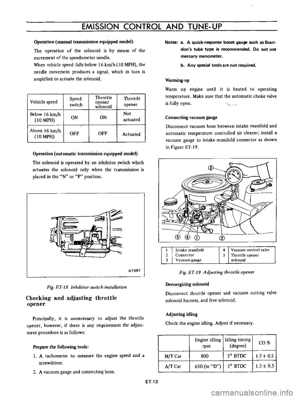
Operation
manual
transmission
equipped
model
The
operation
of
the
solenoid
is
by
means
of
the
movement
of
the
speedometer
needle
When
vehicle
speed
falls
below
16
km
h
10
MPH
the
needle
movement
produces
a
signal
which
in
turn
is
amplified
to
actuate
the
solenoid
I
Vehicle
speed
Speed
Throttle
Throttle
switch
opener
opener
solenoid
Below
16
km
h
Not
10
MPH
ON
ON
actuated
Above
16
km
h
OFF
OFF
Actuated
10
MPH
Operation
automatic
transmission
equipped
model
The
solenoid
is
operated
by
an
inhibitor
switch
which
actuates
the
solenoid
only
when
the
transmission
is
placed
in
the
N
or
P
position
c
fil
rn
AT057
Fig
ET
18
Inhibitor
switch
installation
Checking
and
adjusting
throttle
opener
Principally
it
is
unnecessary
to
adjust
the
throttle
opener
however
if
there
is
any
requirement
the
adjust
ment
procedure
is
as
follows
Prepare
the
following
tools
1
A
tachometer
to
measure
the
engine
speed
and
a
screwdriver
2
A
vacuum
gauge
and
connecting
hose
ET
13
Notes
a
A
quick
response
boost
gauge
such
as
Bour
don
s
tube
type
is
recommended
Do
not
use
mercury
manometer
b
Any
special
tools
are
not
required
Warming
up
Warm
up
engine
until
it
is
heated
to
operating
temperature
Make
sure
that
the
automatic
choke
valve
is
fully
open
Connecting
vacuum
gauge
Disconnect
vacuum
hose
between
intake
manifold
and
automatic
temperature
controlled
air
cleaner
install
a
vacuum
gauge
to
intake
manifold
connector
as
shown
in
Figure
ET
19
1
Intake
manifold
2
Connector
3
Vacuum
gauge
4
Vacuum
control
valve
5
Throttle
opener
solenoid
Fig
ET
19
Adjusting
throttle
opener
Deenergizing
solenoid
Disconnect
throttle
opener
and
vacuum
cutting
valve
solenoid
harness
and
free
solenoid
Adjusting
idling
Check
the
engine
idling
Adjust
if
necessary
Engine
idling
rpm
Idling
timing
I
CO
degree
SO
BTDC
I
L51c0
5
SO
BTDC
I
I
S
1c
0
5
M
T
Car
A
TCar
800
6S0
in
D
Page 394 of 513
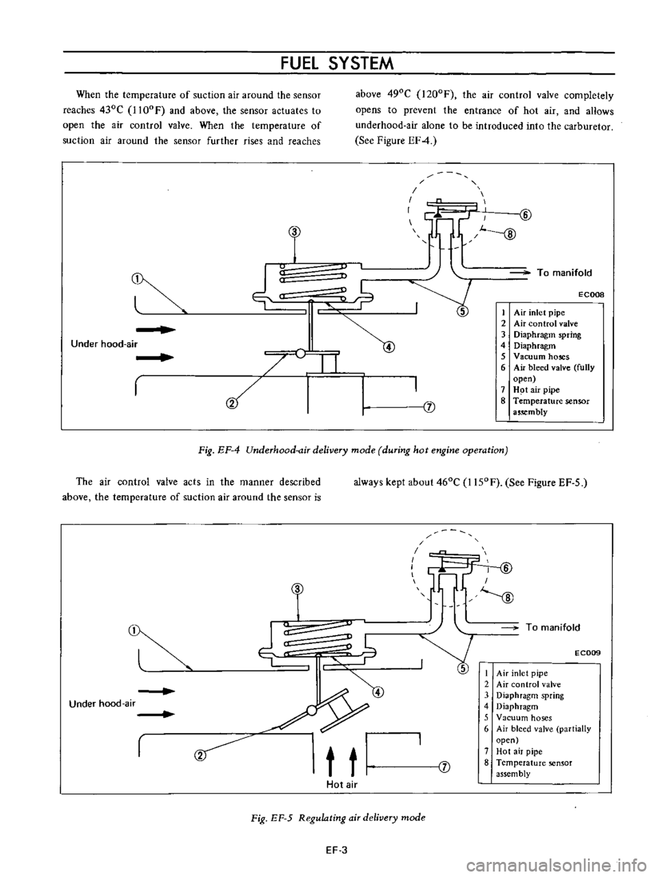
FUEL
SYSTEM
When
the
temperature
of
suction
air
around
the
sensor
reaches
430C
1l00F
and
above
the
sensor
actuates
to
open
the
air
control
valve
When
the
temperature
of
suction
air
around
the
sensor
further
rises
and
reaches
above
490C
I200F
the
air
control
valve
completely
opens
to
prevent
the
entrance
of
hot
air
and
aHows
underhood
air
alone
to
be
introduced
into
the
carburetor
See
Figure
EF4
u
C
I
1f1
lL
GJ
J
To
manifold
ECOOB
j
1
Air
inlet
pipe
2
Air
control
valve
3
Diaphragm
spring
4
Diaphragm
5
Vacuum
hoses
6
Air
bleed
valve
fully
open
7
H
t
air
pipe
8
Temperature
sensor
a5
mbly
Under
hood
air
I
I
Fig
EF
4
Underhood
air
delivery
mode
during
hot
engine
operation
The
air
control
valve
acts
in
the
manner
described
above
the
temperature
of
suction
air
around
the
sensor
is
always
kept
about
460C
I150F
See
Figure
EF
5
r
9
t
t
T
I
I
I
fY
ID
I
J
To
manifold
E
C009
I
Air
inlet
pipe
2
Air
control
valve
3
Diaphragm
spring
4
Diaphragm
5
Vacuum
hoses
6
Air
bleed
valve
partially
open
7
Hot
air
pipe
8
Temperature
sensor
assembly
Under
hood
air
J
Hot
air
Fig
EF
5
Regulating
air
delivery
mode
EF
3
Page 400 of 513
FUEl
SYSTEM
Secondary
throttle
valve
is
operated
by
throttle
lever
The
high
power
and
good
acceleration
are
gained
with
combination
of
the
auxiliary
valve
2
Accelerating
pump
gives
excellent
acceleration
3
The
power
valve
mechanism
is
of
a
vacuum
actuated
boost
type
and
improves
high
speed
driving
4
The
throttle
opener
control
system
Refer
to
Section
ET
incorporates
a
servo
diaphragm
The
servo
dia
phragm
helps
open
the
throttle
valve
at
a
decreasing
speed
so
as
to
reduce
the
emission
of
hydrocarbons
to
a
minimum
5
An
anti
dieseling
solenoid
is
used
as
a
means
of
preventing
dieseling
When
the
ignition
key
is
turned
off
the
fuel
passage
involved
in
the
slow
system
is
closed
and
the
fuel
supply
is
shut
down
completely
6
In
the
choke
mechanism
an
electric
automatic
choke
is
used
to
automatically
control
the
choke
valve
operation
during
the
warm
up
of
the
engine
7
The
carburetor
for
automatic
transmission
is
equipped
with
so
called
dash
pot
that
is
it
makes
smooth
decelerating
without
engine
stall
at
any
operating
condi
tion
These
carburetors
are
quite
similar
in
appearance
as
explained
above
except
the
dash
pot
for
the
au
tomatic
transmission
model
The
differences
in
performance
are
explained
in
the
following
as
necessary
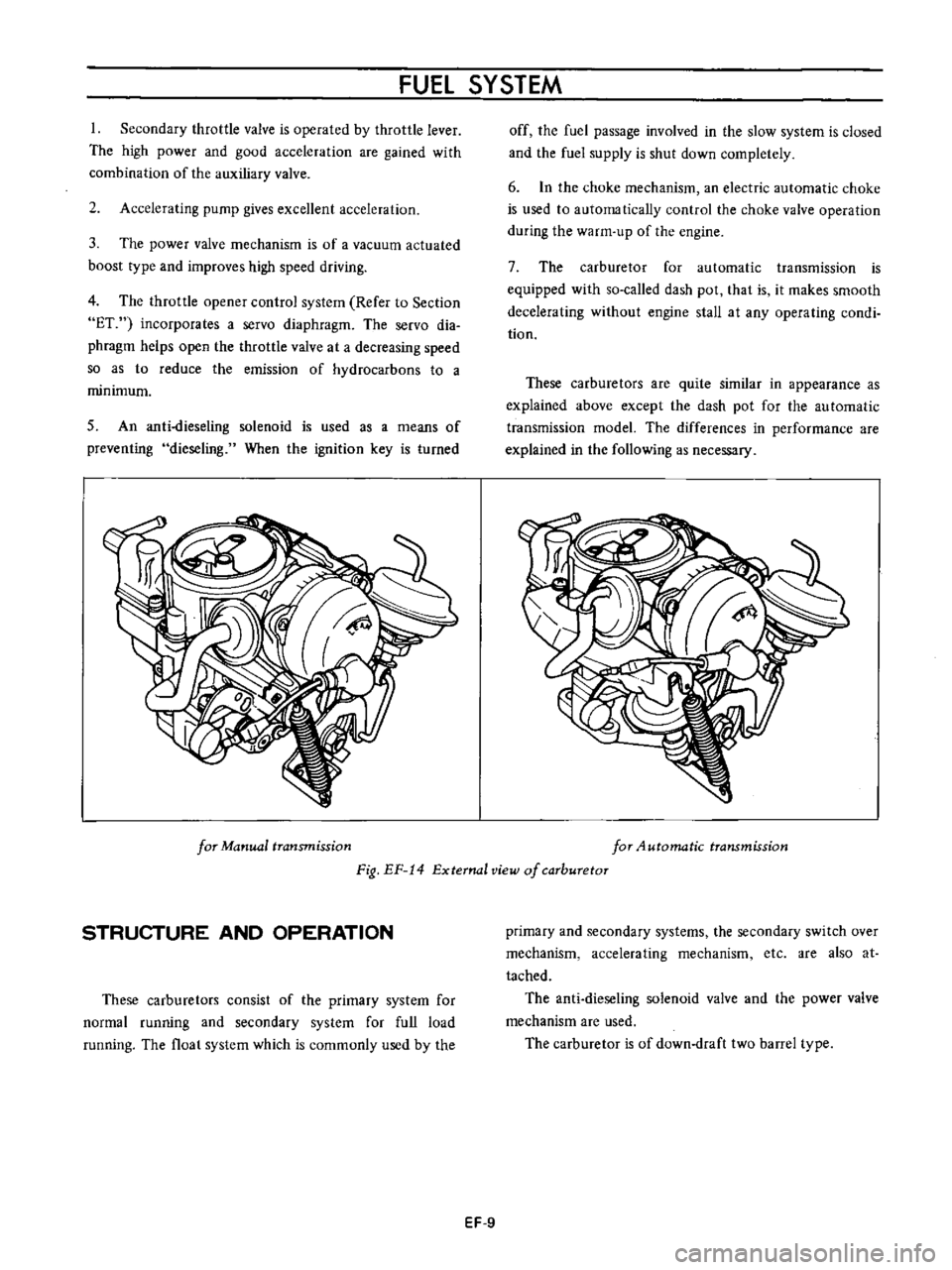
for
Manual
transmission
for
4utomatic
transmission
Fig
EF
14
External
view
of
carburetor
STRUCTURE
AND
OPERATION
These
carburetors
consist
of
the
primary
system
for
normal
running
and
secondary
system
for
full
load
running
The
float
system
which
is
commonly
used
by
the
primary
and
secondary
systems
the
secondary
switch
over
mechanism
accelerating
mechanism
etc
are
also
at
tached
The
anti
dieseling
solenoid
valve
and
the
power
valve
mechanism
are
used
The
carburetor
is
of
down
draft
two
barrel
type
EF
9