Page 190 of 513
SERVI
oE
NuA
r
DATSUN
1200
MODEL
B
1
10
SERIES
I
NISSAN
I
NISSAN
MOTOR
CO
LTD
TOKYO
JAPAN
SECTION
BF
BODY
GENERAL
DESCRIPTION
UNDERBODY
ALIGNMENT
HOOD
FRONT
FENDER
AND
FRONT
END
TRUNK
LID
AND
REAR
BUMPER
DOORS
WINDSHIELD
AND
REAR
WINDOW
VENTILATOR
SEAT
INSTRUMENT
PANEL
ROOM
TRIM
BF
1
BF
9
BF
14
BF
17
BF
19
BF
24
BF
31
BF
37
BF38
BF
42
BF
43
Page 199 of 513

BODY
UNDERBODY
ALIGNMENT
CONTENTS
UNDERBODY
GENERAL
SERVICE
INFORMATION
ALIGNMENT
CHECKING
PROCEDURE
BF
9
BF
9
UNDERBODY
GENERAL
SERVICE
INFORMATION
Since
each
underbody
component
directly
affects
the
overall
strength
of
the
body
it
is
essential
that
proper
welding
sealing
and
rust
proofing
techniques
be
observed
during
service
operations
Whenever
the
body
is
repaired
be
sure
to
provide
the
repaired
body
parts
with
rust
proof
In
the
case
of
a
rust
proofmg
critical
underbody
component
it
is
essential
that
a
good
quality
type
air
dry
primer
such
as
corrosion
resistant
zinc
chromate
be
used
Do
not
use
combination
type
primer
surfacers
ALIGNMENT
CHECKING
PROCEDURE
Misalignment
in
the
underbody
affects
the
front
fender
door
trunk
lid
and
window
alignments
and
also
the
tail
gate
and
rear
body
opening
alignments
in
the
case
of
a
station
wagon
or
van
Underbody
misalignment
particularly
affects
the
suspension
system
thereby
causing
various
problems
that
arise
from
suspension
misalignment
It
is
essential
that
underbody
components
be
aligned
within
the
specified
dimensions
given
in
Figures
BF
13
14
and
IS
In
the
event
of
collision
damage
it
is
important
that
underbody
a1ignrnent
be
thoroughly
checked
and
if
necessary
realigned
to
the
specified
dirnensions
There
are
many
tools
that
may
be
ernployed
to
correct
collision
damage
such
as
frame
straightening
machines
external
pulling
equipment
other
standard
body
jacks
PRINCIPLES
OF
TRAMMING
CAR
PREPARATION
TRAMMING
SEQUENCE
BF
9
BF
10
BF
10
To
assist
in
checking
alignment
of
the
underbody
components
repairing
minor
underbody
damage
or
locating
replacement
parts
the
following
underbody
dimensions
and
alignment
checking
information
are
presented
PRINCIPLES
OF
TRAMMING
All
reference
locations
shown
in
Figure
BF
13
14
and
15
are
symmetrical
at
the
centerline
of
the
vehicle
For
example
wheo
performing
a
crosHheck
of
the
body
floor
panel
dimensions
Figures
BF
I3
14
and
IS
the
diagonal
measurement
should
be
the
same
in
boflii
directions
Cross
checking
operations
are
used
to
deter
mine
the
relationship
between
two
locations
on
the
underbody
To
measure
the
distance
between
any
two
reference
points
on
the
underbody
accurately
two
specifications
are
required
I
The
horizontal
dimension
between
the
two
points
to
be
measured
2
The
vertical
dimension
from
the
datum
line
to
the
points
to
be
measured
For
an
example
the
diagonal
measurement
calculated
on
a
horizontal
plane
between
reference
points
of
dimension
line
L
shown
in
Figure
BF
I3
is
631
3
mm
24
8
in
The
specifications
from
the
datum
line
have
a
vertical
height
difference
of
11
6
mm
0
456
in
between
the
forward
location
of
dimension
L
at
vertical
dimension
80
0
mm
3
150
in
and
the
rearward
location
of
dimension
L
at
vertical
dimension
91
6
mm
3
606
in
The
vertical
pointer
used
at
the
forward
location
should
be
positioned
so
as
to
extend
11
6
mm
0
456
in
further
from
the
tram
bar
than
the
BF
9
Page 209 of 513

BODY
I
1
I
Ik
I
ro
I
W
a
21
zrl
l
11
J
1
3781
I
1
Ii
100
tJ94t
I
100
3
94
0
0551
A
I
10013
94
1
510
0984
100
13
94
I
J
10
1378
2010
787
L
I
l
0
433
O
I
l
JS
348
13
7
5
1
77
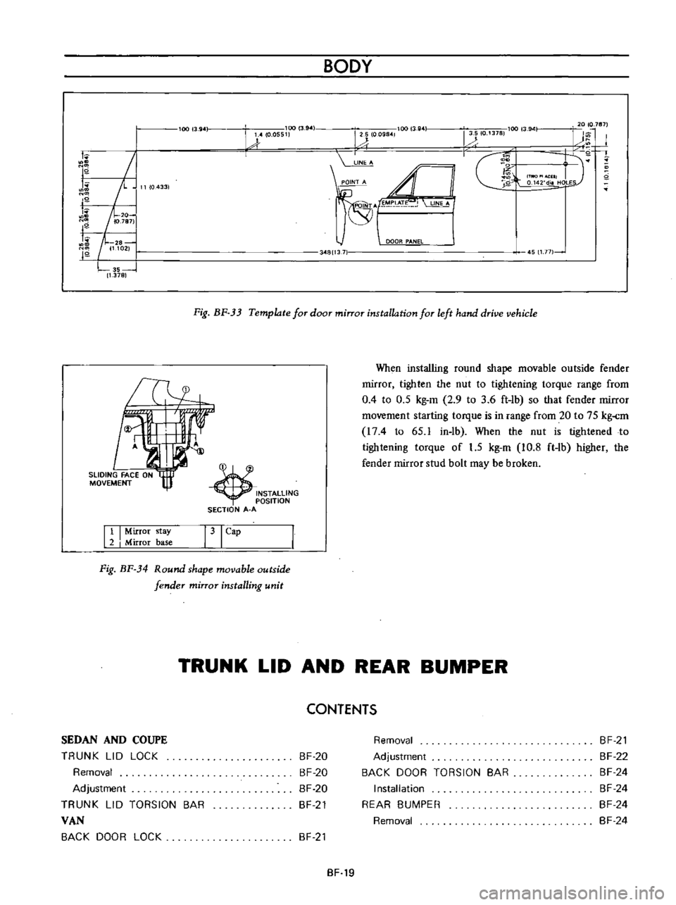
Fig
BF
33
Template
for
door
mirror
installation
for
left
hand
drive
vehicle
INSTALLING
OSITION
SECTION
A
A
When
installing
round
shape
movable
outside
fender
rnirror
tighten
the
nut
to
tightening
torque
range
from
0
4
to
0
5
kg
m
2
9
to
3
6
ft
lb
so
that
fender
rnirror
rnovernent
starting
torque
is
in
range
from
20
to
75
kg
rn
I74
to
65
1
in
lb
When
the
nut
is
tightened
to
tightening
torque
of
1
5
kg
m
10
8
ft
lb
higher
the
fender
mirror
stud
bolt
may
be
broken
Tl4
11
I
Mirror
stay
2
I
Mirror
base
31
Cap
Fig
BF
34
Round
shape
movable
outside
fender
mirror
installing
unit
TRUNK
LID
AND
REAR
BUMPER
CONTENTS
SEDAN
AND
COUPE
TRUNK
LID
LOCK
Removal
Adjustment
TRUNK
LID
TORSION
BAR
VAN
BACK
DOOR
LOCK
BF
20
BF
20
BF
20
BF
21
Removal
Adjustment
BACK
DOOR
TORSION
BAR
Installation
REAR
BUMPER
Removal
BF
21
BF
22
BF
24
BF
24
BF
24
BF
24
BF
21
BF
19
Page 210 of 513

BODY
SEDAN
AND
COUPE
CD
@
h
r
1
@
@
II
I
Trunk
lid
2
Trunk
lid
lock
assembly
13
I
Trunk
lid
weatherstrip
4
Hinge
fixing
pin
15
I
Trunk
lid
hinge
6
Striker
assembly
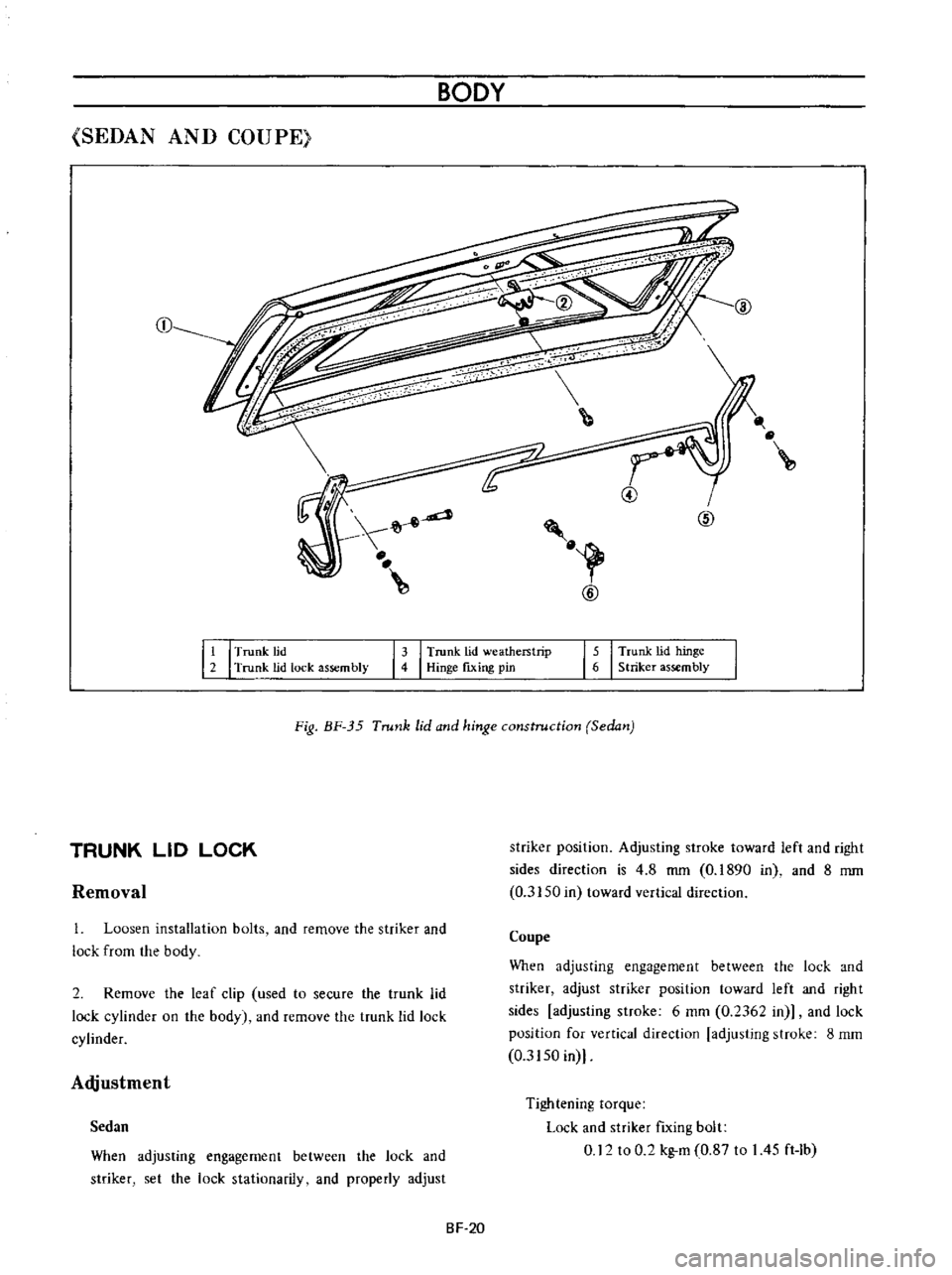
Fig
BF
35
Trunk
lid
and
hinge
construction
Sedan
Removal
striker
position
Adjusting
stroke
toward
left
and
right
sides
direction
is
4
8
mm
0
1890
in
and
8
mm
0
3150
in
toward
vertical
direction
TRUNK
LID
LOCK
1
Loosen
installation
bolts
and
remove
the
striker
and
lock
from
the
body
Coupe
When
adjusting
engagement
between
the
lock
and
striker
adjust
striker
position
toward
left
and
right
sides
adjusting
stroke
6
mm
0
2362
in
and
lock
position
for
vertical
direction
adjusting
stroke
8
mm
0
3150
in
2
Remove
the
leaf
clip
used
to
secure
the
trunk
lid
lock
cylinder
on
the
body
and
remove
the
trunk
lid
lock
cylinder
Adjustment
When
adjusting
engagement
between
the
lock
and
striker
set
the
lock
stationarily
and
properly
adjust
Tightening
torque
Lock
and
striker
fIxing
bolt
0
12
to
0
2
kg
m
0
87
to
I
45
ft
Ib
Sedan
SF
20
Page 211 of 513
BODY
TRUNK
LID
TORSION
BAR
The
procedures
of
installing
torsion
bar
are
indicated
as
follows
ill
ID
f
Jw
V
@
@
Fig
BF
36
Installing
torsion
bar
1
Closed
position
2
Rotation
center
of
trunk
lid
hinge
3
Trunk
lid
hinge
4
Trunk
lid
torsion
bar
5
Rear
waist
connector
Note
When
installing
the
to
ion
bar
use
to
ion
bar
wrench
special
tool
ST087100001
VAN
t
9
@
i
Fig
BF
37
Back
door
and
hinge
constructions
BACK
DOOR
LOCK
1
Back
door
hinge
torsion
bar
2
Back
door
hinge
3
Back
door
4
Back
door
lock
rod
5
Lock
6
Striker
7
Striker
shim
8
Back
door
side
dovetail
9
Side
dovetail
shim
10
Back
door
bumper
11
Back
door
bumper
plate
Removal
2
Remove
the
lock
cylinder
securing
leaf
clip
so
as
to
free
the
lock
cylinder
and
remove
the
back
door
lock
rod
from
the
lock
cylinder
I
Remove
the
back
door
trim
and
sealing
screen
BF
21