1973 DATSUN B110 horn
[x] Cancel search: hornPage 162 of 513

Iii
I
o
t
I
I
CHASSIS
Fig
ST
2
Steering
wheel
REMOVAL
1
Remove
the
horn
ring
and
remove
the
steering
wheel
nut
and
pull
out
the
steering
wheel
by
the
use
of
a
Steer
ing
wheel
puller
ST27180000
3
Remove
the
turn
signal
and
lighting
switch
com
pletely
4
Remove
the
hand
lever
assembly
from
the
control
rod
assembly
by
unscrewing
the
fIxing
bolts
5
Remove
two
fIxing
bolts
used
to
secure
the
steering
column
to
the
instrument
panel
ST27180000
Fig
ST
3
Removing
steering
wheel
lock
nut
Note
The
horn
ring
can
be
easily
removed
by
two
bolts
2
Remove
the
steering
column
shell
Fig
ST
4
Removing
steering
column
upper
side
ST
2
Page 235 of 513
DATSUN
1200
MODEL
B
11
0
SERIES
I
NISSAN
I
NISSAN
MOTOR
CO
LTD
TOKYO
JAPAN
SECTION
BE
BODY
ELECTRICAL
WIRING
FUSE
LIGHTING
SYSTEM
HORN
METERS
AND
GAUGES
WINDSHIELD
WIPER
AND
WASHER
IGNITION
SWITCH
AND
STEERING
LOCK
CLOCK
RADIO
HEATER
BE
1
BE
6
BE
7
BE
15
BE
18
BE
26
BE
29
BE
31
BE
32
BE
34
Page 245 of 513
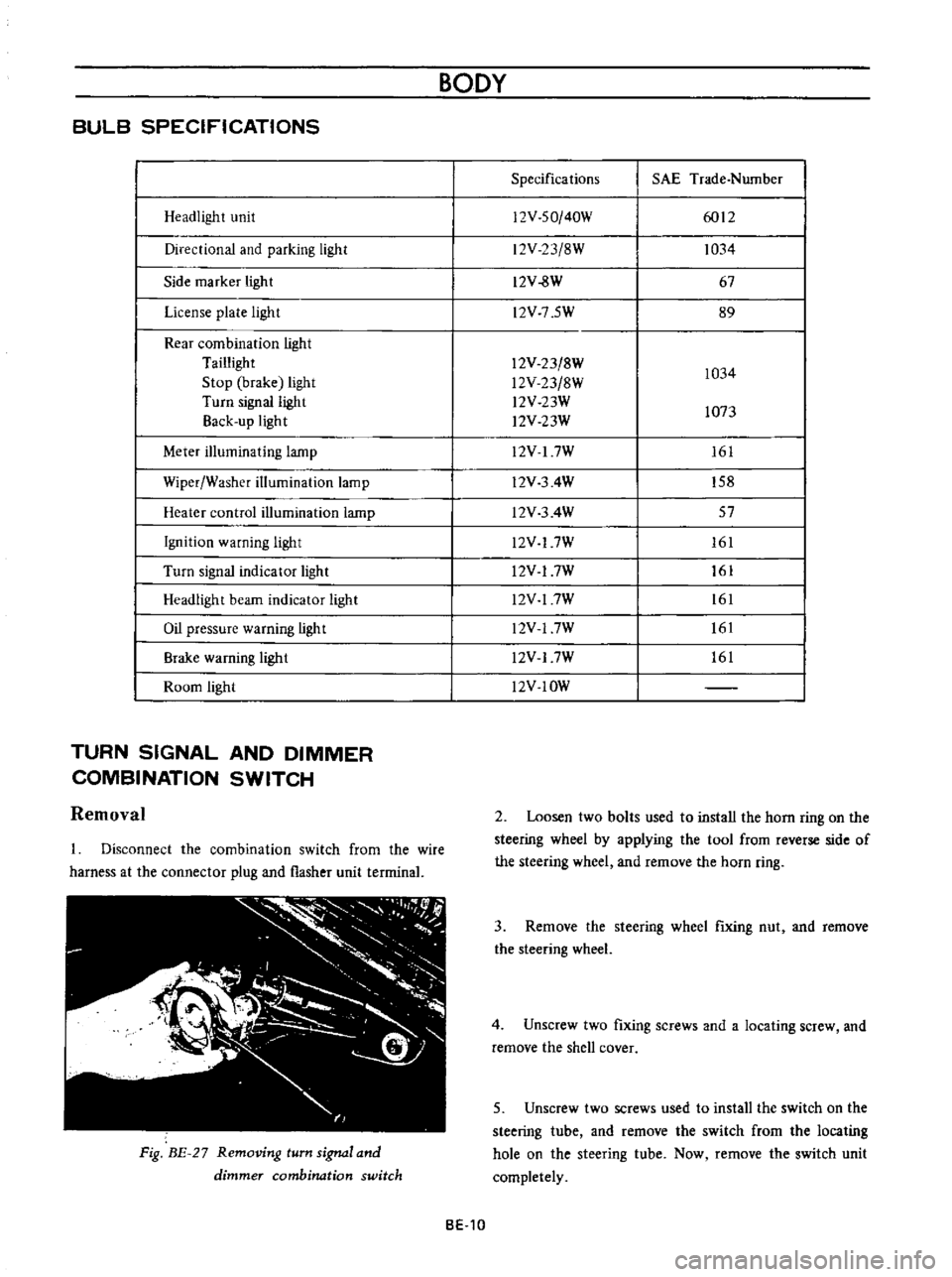
BULB
SPECIFICATIONS
Headlight
unit
Directional
and
parking
light
Side
marker
light
License
plate
light
Rear
combination
light
Taillight
Stop
brake
light
Turn
signal
light
Back
up
light
Meter
illuminating
lamp
Wiper
Washer
illumination
lamp
Heater
control
illumination
lamp
Ignition
warning
light
Turn
signal
indicator
light
Headlight
beam
indicator
light
Oil
pressure
warning
light
Brake
warning
ligh
t
Room
light
TURN
SIGNAL
AND
DIMMER
COMBINATION
SWITCH
Removal
Disconnect
the
combination
switch
from
the
wire
harness
at
the
connector
plug
and
flasher
unit
terrninal
Fig
BE
27
Removing
turn
signal
and
dimmer
combination
switch
BODY
Specifications
SAE
Trade
Number
12V
SO
40W
6012
12V
23
8W
1034
12V
8W
67
l2V
7
5W
89
12V
23
8W
1034
l2V
23
8W
l2V
23W
1073
l2V
23W
12V
I
7W
161
l2V
3
4W
158
l2V
3
4W
57
l2V
17W
161
l2V
17W
161
l2V
17W
161
l2V
17W
161
l2V
17W
161
l2V
IOW
2
Loosen
two
bolts
used
to
install
the
horn
ring
on
the
steering
wheel
by
applying
the
tool
from
reverse
side
of
the
steering
wheel
and
remove
the
horn
ring
3
Remove
the
steering
wheel
fixing
nut
and
remove
the
steering
wheel
4
Unscrew
two
fixing
screws
and
a
locating
screw
and
remove
the
shell
cover
5
Unscrew
two
screws
used
to
install
the
switch
on
the
steering
tube
and
remove
the
switch
from
the
locating
hole
on
the
steering
tube
Now
remove
the
switch
unit
completely
BE
10
Page 250 of 513
Flashing
cycle
varies
BODY
ELECTRICAL
Faulty
contact
of
power
supply
circuit
from
ignition
switch
to
fuse
Tail
and
stop
lamp
license
lamp
back
up
lamp
Condition
Both
left
and
right
lamps
do
not
light
Probable
cause
Blown
off
fuse
or
faulty
contact
Defective
stop
larnp
switch
or
backup
lamp
switch
or
faulty
contact
Stop
larnps
and
backup
lamp
only
Faulty
grounding
Only
one
side
lamp
Burnt
out
lamp
bulb
f1lament
lights
Brightness
of
one
side
lamp
differs
from
the
other
HORN
Removal
Adjustment
Faulty
contact
of
connector
ter
minal
and
or
socket
Faulty
contact
of
connector
ter
minal
and
or
socket
BE
16
BE
16
BE
16
When
the
windshield
wiper
which
uses
the
ignition
for
power
supply
is
operated
flashing
cycle
and
brightness
change
Method
of
inspection
Check
the
fuse
for
fusing
and
faulty
contact
When
two
lead
wires
of
the
switch
are
connected
and
the
lamp
lights
the
larnp
and
circuit
are
normal
All
rear
combination
lamps
do
not
light
HORN
CONTENTS
TROUBLE
DIAGNOSES
AND
CORRECTIONS
BE
15
Repair
as
required
Corrective
action
When
the
fuse
is
fused
detect
and
COf
rect
the
cause
and
replace
the
fuse
Replace
the
switch
or
repair
the
connector
terrninal
Repair
the
grounding
cable
contact
Replace
the
larnp
with
a
new
one
Repair
or
replace
Repair
or
replace
if
required
BE
17
Page 251 of 513
9HORN
r
I
01
8ATTERY
HI
IGI
s
ILl
C
iORN
BODY
FUSE
H
S
HORN
BUTTON
BGI
J
H
B
S
Il
I
n6lm
I
L
J
L
HORN
RELAY
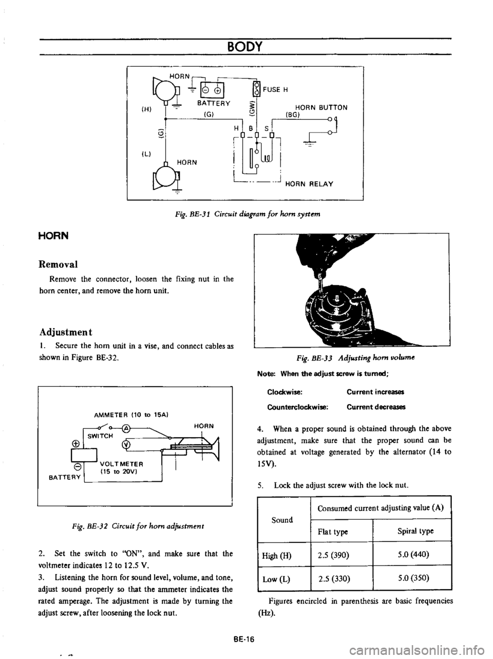
Fig
BE
3l
Circuit
diagram
for
hom
syrtem
HORN
Removal
Remove
the
connector
loosen
the
fixing
nut
in
the
horn
center
and
remove
the
horn
unit
Adjustment
1
Secure
the
horn
unit
in
a
vise
and
connect
cables
as
shown
in
Pigure
BE
32
AMMETER
110
to
15AI
Isw
f
@
113
I
VOLTMETER
I
15
to
20VI
BATTERY
HORN
Fig
BE
32
Circuit
for
ham
adjustment
2
Set
the
switch
to
ON
and
rnake
sure
that
the
voltmeter
indicates
12
to
12
5
V
3
Listening
the
horn
for
sound
level
volurne
and
tone
adjust
sound
properly
so
that
the
amrneter
indicates
the
rated
amperage
The
adjustment
is
made
by
turning
the
adjust
screw
after
loosening
the
lock
nut
Fig
BE
33
Adjusting
hom
IIOlume
Note
When
the
adjust
screw
is
turned
Clockwise
Counterclockwise
Current
increases
Current
decreases
4
When
a
proper
sound
is
obtained
through
the
above
adjustment
rnake
sure
that
the
proper
sound
can
be
obtained
at
voltage
generated
by
the
alternator
14
to
l5V
5
Lock
the
adjust
screw
with
the
lock
nut
Consumed
current
adjusting
value
A
Sound
Plat
type
Spiral
type
High
H
2
5
390
5
0
440
Low
L
2
5
330
5
0
350
Figures
encircled
in
parenthesis
are
basic
frequencies
Hz
BE
16
Page 252 of 513
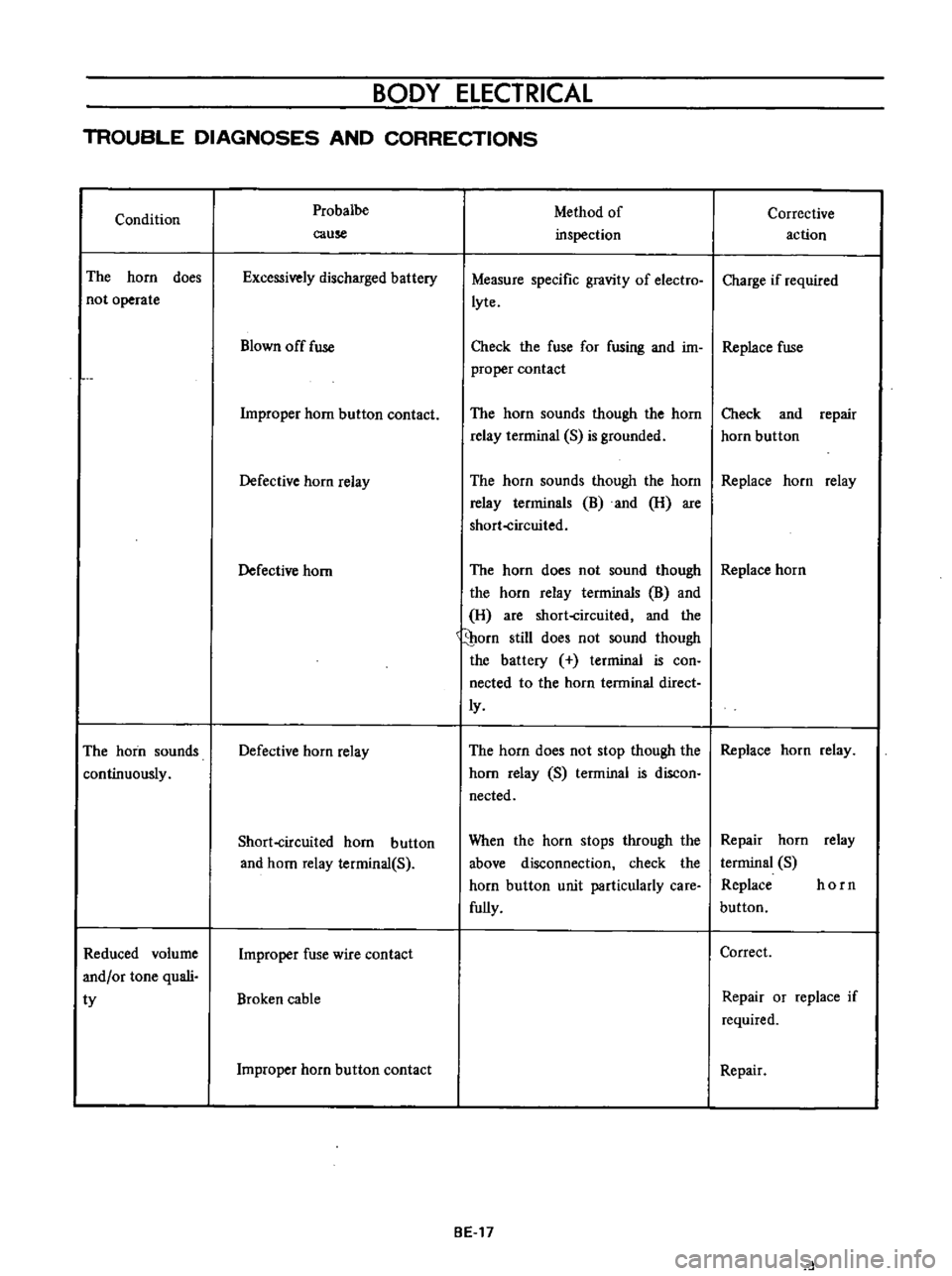
BODY
ELECTRICAL
TROUBLE
DIAGNOSES
AND
CORRECTIONS
Condition
The
horn
does
not
operate
The
horn
sounds
continuously
Reduced
volume
and
or
tone
quali
ty
Probalbe
cause
Excessively
discharged
battery
Blown
off
fuse
Improper
horn
button
contact
Defective
horn
relay
Defective
horn
Defective
horn
relay
Short
circuited
horn
button
and
horn
relay
terminal
S
Improper
fuse
wire
contact
Broken
cable
Improper
horn
button
contact
Method
of
inspection
Measure
specific
gravity
of
electro
lyte
Corrective
action
Charge
if
required
Check
the
fuse
for
fusing
and
im
Replace
fuse
proper
contact
The
horn
sounds
though
the
horn
relay
terrninal
S
is
grounded
Check
and
repair
horn
button
The
horn
sounds
though
the
horn
Replace
horn
relay
relay
terrninals
B
and
H
are
short
circuited
The
horn
does
not
sound
though
Replace
horn
the
horn
relay
terminals
B
and
H
are
short
circuited
and
the
porn
still
does
not
sound
though
the
battery
terminal
is
con
nected
to
the
horn
terminal
direct
ly
The
horn
does
not
stop
though
the
Replace
horn
relay
horn
relay
S
terminal
is
discon
nected
When
the
horn
stops
through
the
above
disconnection
check
the
horn
button
unit
particularly
care
fully
BE
17
Repair
horn
relay
terminal
S
Replace
horn
button
Correct
Repair
or
replace
if
required
Repair
d
Page 268 of 513
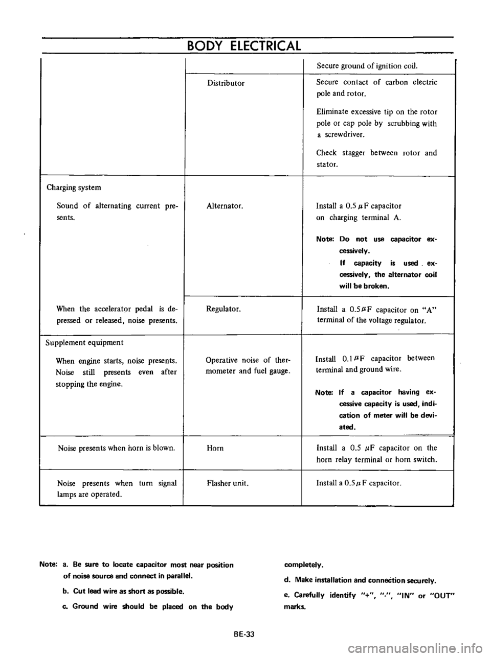
BODY
ELECTRICAL
Distributor
Secure
ground
of
ignition
coil
Secure
contact
of
carbon
electric
pole
and
rotor
Eliminate
excessive
tip
on
the
rotor
pole
or
cap
pole
by
scrubbing
with
a
screwdriver
Check
stagger
between
rotor
and
stator
Charging
system
Sound
of
alternating
current
pre
sents
Alternator
Install
a
0
5
l
F
capacitor
on
charging
terminal
A
Note
Do
not
use
capacitor
ex
cessively
If
capacity
is
used
ex
cessively
the
alternator
coil
will
be
broken
When
the
accelerator
pedal
is
de
pressed
or
released
noise
presents
Regulator
Install
a
0
5
l
F
capacitor
on
A
terrninal
of
the
voltage
regulator
Supplement
equipment
When
engine
starts
noise
presents
Noise
still
presents
even
after
stopping
the
engine
Operative
noise
of
ther
rnometer
and
fuel
gauge
Install
0
1
l
F
capacitor
between
terminal
and
ground
wire
Note
If
a
capacitor
having
ex
cessive
capacity
is
used
indi
cation
of
meter
will
be
devi
ated
Noise
presents
when
horn
is
blown
Horn
Install
a
0
5
IF
capacitor
on
the
horn
relay
terminal
or
horn
switch
Noise
presents
when
turn
signal
lamps
are
operated
Flasher
unit
Install
a
0
5
l
F
capacitor
Note
a
Be
sure
to
locate
capacitor
most
near
position
of
noise
source
and
connect
in
parallel
completely
d
Make
installation
and
conneCtion
securely
b
Cut
lead
wire
as
short
as
possible
c
Ground
wire
should
be
placed
on
the
body
e
Carefully
identify
marks
IN
or
OUT
BE
33
Page 344 of 513
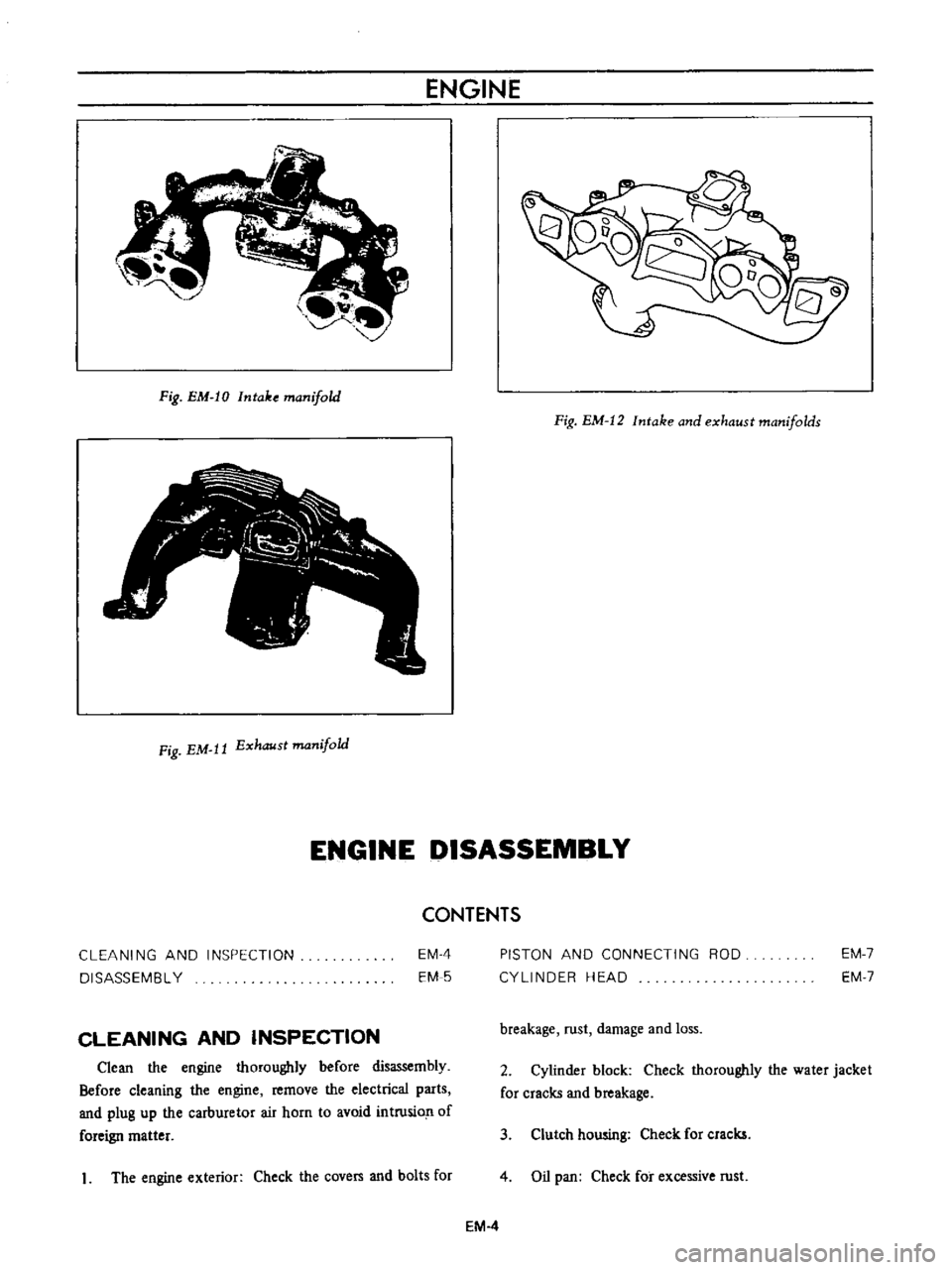
ENGINE
Fig
EM
IO
Intake
manifold
Fig
EM
12
Intake
and
exhaust
manifolds
Fig
EM
It
Exhaust
manifold
ENGINE
DISASSEMBLY
CONTENTS
CLEANING
AND
INSPECTION
DISASSEMBL
Y
EM
4
EM
5
PISTON
AND
CONNECTING
ROD
CYLINDER
HEAD
EM
7
EM
7
CLEANING
AND
INSPECTION
breakage
rust
damage
and
loss
Clean
the
engine
thoroughly
before
disassembly
Before
cleaning
the
engine
remove
the
electrical
parts
and
plug
up
the
carburetor
air
horn
to
avoid
intrusio
n
of
foreign
matter
2
Cylinder
block
Check
thoroughly
the
water
jacket
for
cracks
and
breakage
3
Clutch
howing
Check
for
cracks
1
The
engine
exterior
Check
the
covers
and
bolts
for
4
Oil
pan
Check
for
excessive
rust
EM
4