1973 DATSUN B110 weight
[x] Cancel search: weightPage 37 of 513

AUTOMATIC
TRANSMISSION
REMOVAL
AND
INSTAllATION
TRANSMISSION
ASSEMBLY
Removal
Installation
TRANSMISSION
ASSEMBLY
When
dismounting
the
automatic
transmission
from
a
vehicle
pay
at
tention
to
the
following
points
1
Before
dismounting
the
trans
mission
rigidly
inspect
it
by
aid
of
the
Troubleshooting
Chart
and
dis
mount
it
only
when
considered
to
be
necessary
2
Dismount
the
transmission
with
utmost
care
and
when
mounting
observe
the
tightening
torque
indi
cated
on
another
table
not
to
exert
excessive
force
Removal
In
dismounting
automatic
transmis
sion
from
vehicle
proceed
as
follows
i
Disconnect
battery
ground
cable
from
terminal
2
Jack
up
car
and
support
its
weight
on
safety
stands
Recommend
a
hydraulic
hoist
or
open
pit
be
utilized
if
available
Make
sure
that
safety
is
insured
3
Remove
propeller
shaft
Note
Plug
up
the
opening
in
the
rear
extension
to
prevent
oil
from
flowing
out
4
Disconnect
front
exhaust
tube
5
Disconnect
selector
range
lever
from
manual
shaft
6
Disconnect
wire
connections
at
inhibitor
switch
CONTENTS
AT
33
AT
33
AT
33
TRANSMISSION
CONTROL
LINKAGE
Removal
and
installation
Adjustment
AT
35
AT
36
AT
36
7
Disconnect
vacuum
tube
from
vacuum
diaphragm
and
wire
connec
tions
at
downshift
solenoid
8
Disconnect
speedometer
cable
from
rear
extension
9
Disconnect
oil
charging
pipe
10
Support
engine
by
locating
a
jack
under
oil
pan
with
a
wooden
block
used
between
oil
pan
and
jack
Support
transmission
by
means
of
3
transmission
jack
11
Detach
converter
housing
dust
cover
Remove
bolts
securing
torque
converter
to
drive
plate
See
Figure
AT
47
AT265
Fig
AT
47
Removing
torque
converter
attaching
bolt
Note
Before
removing
torque
con
verter
scribe
match
marks
on
two
parts
so
that
they
may
be
replaced
in
their
original
posi
tions
at
assembly
12
Disconnect
engine
moun
t
and
hand
lever
bracket
by
removing
two
2
rear
engine
mount
securing
bolts
and
two
2
crossmember
mounting
bolts
13
Remove
starter
motor
14
Remove
bolts
securing
transmis
sion
to
engine
After
removing
these
AT
33
bolts
support
engine
and
transmission
with
jack
and
lower
the
jack
gradually
until
transmission
can
be
removed
and
take
out
transmission
under
the
car
Note
Plug
up
the
opening
such
as
oil
charging
pipe
rear
extension
etc
Installation
Installation
of
automatic
transmis
sion
on
vehicle
is
reverse
order
of
removal
However
observe
the
follow
ing
installation
notes
Drive
plate
mnout
Turn
crankshaft
one
full
turn
and
measure
drive
plate
mnou
t
with
indi
cating
finger
of
a
dial
gauge
rested
against
plate
See
Figure
AT48
Replace
drive
plate
if
in
excess
of
0
5
mm
0
020
in
Maximum
allowable
mnout
0
3
mm
0
012
in
A
T266
Fig
A
T
48
Measuring
drive
plate
runout
2
Installation
of
torque
converter
Line
up
notch
in
torque
converter
with
that
in
oil
pump
Be
extremely
careful
not
to
cause
undue
stresses
in
parts
in
installing
torque
converter
See
Figure
A
T
49
Page 79 of 513
CHASSIS
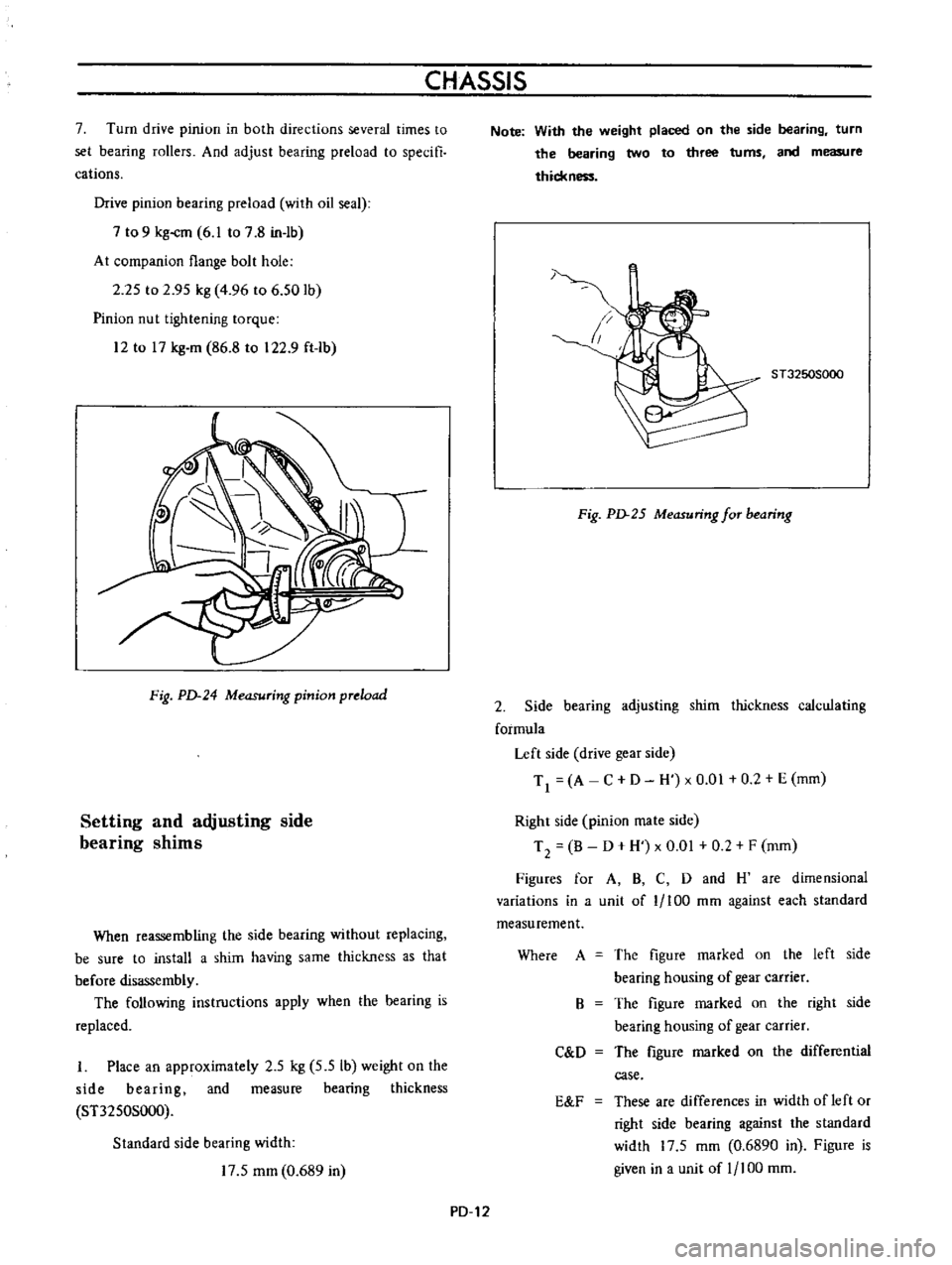
7
Turn
drive
pinion
in
both
directions
several
times
to
set
bearing
rollers
And
adjust
bearing
preload
to
specifi
cations
Drive
pinion
bearing
preload
with
oil
seal
7
to
9
kg
cm
6
1
to
7
8
in
1b
At
companion
flange
bolt
hole
2
25
to
2
95
kg
4
96
to
6
50
1b
Pinion
nut
tightening
torque
12
to
17
kg
m
86
8
to
122
9
ft
1b
Fig
PD
24
Measuring
pinion
preload
Setting
and
adjusting
side
bearing
shims
When
reassembling
the
side
bearing
without
replacing
be
sure
to
install
a
shim
having
same
thickness
as
that
before
disassembly
The
following
instructions
apply
when
the
hearing
is
replaced
I
Place
an
approximately
2
5
kg
5
5
Ib
weight
on
the
side
bearing
and
measure
bearing
thickness
ST3250S000
Standard
side
bearing
width
17
5
mm
0
689
in
Note
With
the
weight
placed
on
the
side
bearing
turn
the
bearing
two
to
three
turns
and
measure
thickn
1
ST3250S000
Fig
PD
25
Measuring
for
bearing
2
Side
bearing
adjusting
shim
thickness
calculating
formula
Left
side
drive
gear
side
Tl
A
C
D
H
xO
01
0
2
E
mm
Right
side
pinion
mate
side
T
2
B
D
H
x
0
01
0
2
F
mm
Figures
for
A
B
C
D
and
H
are
dimensional
variations
in
a
unit
of
1
100
mm
against
each
standard
measurement
Where
A
The
figure
marked
on
the
left
side
bearing
housing
of
gear
carrier
The
figure
marked
on
the
right
side
bearing
housing
of
gear
carrier
The
figure
marked
on
the
differential
case
B
C
D
E
F
These
are
differences
in
width
of
left
or
right
side
bearing
against
the
standard
width
17
5
mm
0
6890
in
Figure
is
given
in
a
unit
of
1
100
mm
PD
12
Page 116 of 513
REAR
AXLE
REAR
SUSPENSION
REAR
AXLE
CONTENTS
DESCRIPTION
REAR
AXLE
SHAFTS
Removal
RA
1
RA
l
RA
l
8
Inspection
Assembly
RA
3
RA
3
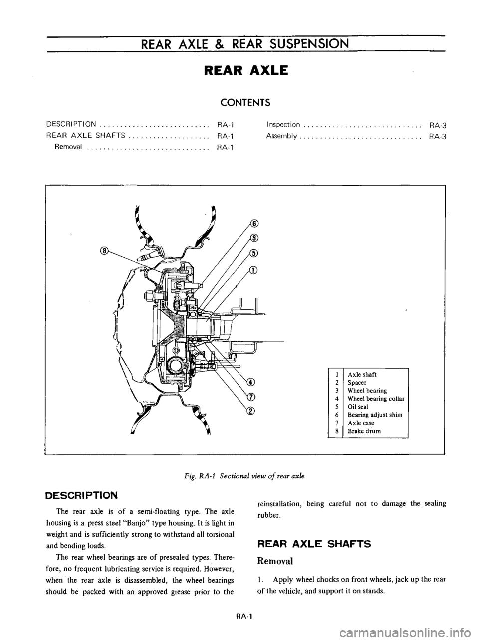
1
Axle
shaft
2
Spacer
3
Wheel
bearing
4
Wheel
bearing
collar
5
Oil
seal
6
Bearing
adjust
shim
7
Axle
case
8
Brake
drum
DESCRIPTION
Fig
RA
l
Sectional
view
of
rear
axle
The
rear
axle
is
of
a
semi
floating
type
The
axle
housing
is
a
press
steel
Banjo
type
housing
It
is
light
in
weight
and
is
sufficiently
strong
to
withstand
all
torsional
and
bending
loads
The
rear
wheel
bearings
are
of
presea1ed
types
There
fore
no
frequent
lubricating
service
is
required
However
when
the
rear
axle
is
disassembled
the
wheel
bearings
should
be
packed
with
an
approved
grease
prior
io
the
reinstallation
being
careful
not
to
damage
the
sealing
rubber
REAR
AXLE
SHAFTS
Removal
Apply
wheel
chocks
on
front
wheels
jack
up
the
rear
of
the
vehicle
and
support
it
on
stands
RA
l
Page 157 of 513

CHASSIS
Tire
rotation
Tires
wear
unevenly
and
become
unbalanced
according
to
running
distance
Uneven
tire
wear
often
results
in
tire
noise
whkh
is
attributed
to
rear
axle
gears
bearing
ell
Meanwhile
the
front
tires
tend
to
wear
unevenly
because
of
front
wheel
alignment
Accordingly
to
equalize
tire
wear
it
is
necessary
to
rotate
tires
every
10
000
km
6
000
miles
of
operation
RIGHT
FRONT
RIGHT
REAR
r
1
Xl
L
J
LEFT
FRONT
LEFT
REAR
Fig
WT
2
Tire
rotation
The
tires
are
provided
with
tread
wear
indicator
at
six
places
around
tire
circumference
indicating
1
6
nun
0
16
in
tread
depth
When
the
tires
wear
and
then
the
marks
a
ppear
replace
them
with
new
ones
TREAD
WEAR
INDICATOR
7
TREAD
m
Y
X
W
X
v
w
WH024
Fig
WI
3
Tread
wear
illdicator
To
change
tire
with
wheel
using
a
jack
in
the
safe
manner
observe
the
following
procedures
I
Apply
parking
brake
and
block
front
wheels
when
rear
wheel
is
being
changed
2
Remove
wheel
cap
and
loosen
wheel
nuts
3
Place
jack
at
jacking
point
instructed
under
General
Information
and
raise
car
until
wheel
clears
ground
4
Remove
wheel
nuts
and
whed
from
drum
5
To
install
wheel
reverse
the
above
steps
Tighten
whed
nuts
in
criss
cross
fashion
to
8
0
to
9
0
kg
m
58
to
65
ft
lb
Note
Never
get
under
the
car
while
it
is
supported
only
by
the
jack
Always
use
safety
stands
to
support
the
side
member
of
body
construction
when
you
must
get
beneath
the
car
INSPECTION
Wheel
balance
The
wheel
and
tire
assembly
should
be
kept
balanced
statically
and
dynamically
Proper
tire
balance
is
necessary
when
driving
the
car
at
high
speeds
Consequently
the
wheel
and
tire
assembly
should
be
properly
rebalanced
whenever
puncture
is
repaired
The
wheel
and
tire
assembly
becomes
out
of
balance
according
to
uneven
tire
wear
Severe
acceleration
and
braking
or
fast
cornering
is
the
cause
of
wear
on
tire
resulting
in
unbalance
of
tire
and
wheel
assembly
The
symptom
of
unbalance
appears
as
tramp
car
shake
and
steering
trouble
To
correct
unbalance
use
proper
wheel
balancer
Maximum
allowable
unbalance
165
gr
cm
2
3
in
ol
at
rim
circumferences
Balance
weight
10
to
70
gr
0
35
to
2
47
Ol
at
10
gr
0
35
Ol
interval
Note
Be
sure
to
place
the
correct
balance
weights
on
the
inner
edge
of
rim
as
shown
in
Figure
WT
4
Wheel
and
tire
In
order
to
ensure
satisfactory
steering
condition
as
well
as
maximum
tire
life
proceed
as
follows
I
Check
wheel
rim
especially
rim
flange
and
bead
seat
for
rust
distortion
cracks
or
other
defects
which
might
cause
air
leaks
Function
of
tubeless
tire
depends
on
a
good
seal
between
tire
bead
and
wheel
rim
Thoroughly
remove
rust
dust
oxidized
rubber
or
sand
from
wheel
rim
with
wire
brush
emery
cloth
or
paper
Use
dial
gauge
to
examine
wheel
rim
for
lateral
and
diametral
run
out
WT
4
Page 200 of 513
pointer
used
at
the
rearward
lut
atiol1
With
the
proper
scttings
the
tram
bar
will
be
on
a
piane
parallel
to
that
of
the
body
The
exception
to
this
would
be
wht
n
one
of
the
reterence
locations
is
induded
in
the
misaligned
area
then
the
parallel
plane
between
the
body
and
the
tram
bar
may
not
prevail
After
completiun
of
the
repairs
the
tram
gauge
should
be
set
at
the
specitled
dimension
to
check
the
accuracy
of
the
repair
operation
CAR
PREPARATION
Preparing
the
car
for
the
underbody
alignment
check
involves
the
following
Place
the
car
on
a
level
surface
2
The
weight
of
the
car
should
be
supported
at
the
wheel
locations
3
A
visual
damage
inspection
should
be
made
to
eliminate
unnecessary
measuring
Obviously
damaged
or
misaligned
areas
may
often
be
located
visually
BODY
TRAMMING
SEQUENCE
The
tramming
sequence
will
varv
depending
upon
the
nature
and
IOl
atiun
uf
the
misaligned
area
Priur
to
performing
any
tramming
uperation
the
h
uracy
of
refereJlce
points
to
be
used
must
be
determined
A
measurement
that
originates
from
a
reference
point
included
in
a
damaged
area
will
produce
untrue
results
and
confuse
the
evaluation
of
the
underbody
condition
Unlike
the
conventional
type
of
frame
design
the
unitized
type
of
body
construction
seldom
develops
the
condition
of
diamond
in
the
floor
pan
area
as
a
result
of
front
or
rear
end
collision
Therefore
underbody
alignment
checking
can
usually
originate
from
the
body
floor
pan
area
If
inspection
indicates
that
these
locations
have
been
disturbed
and
are
not
suitable
for
measuring
one
of
the
undamaged
suspension
locations
should
be
used
as
an
initial
reference
point
If
a
rare
situation
should
exist
where
all
of
these
lucalions
are
not
suitable
as
reference
points
repair
operations
should
begin
with
the
body
floor
pan
area
All
other
underbody
components
should
be
aligned
progressively
from
this
area
MEMO
BF
10
Page 230 of 513
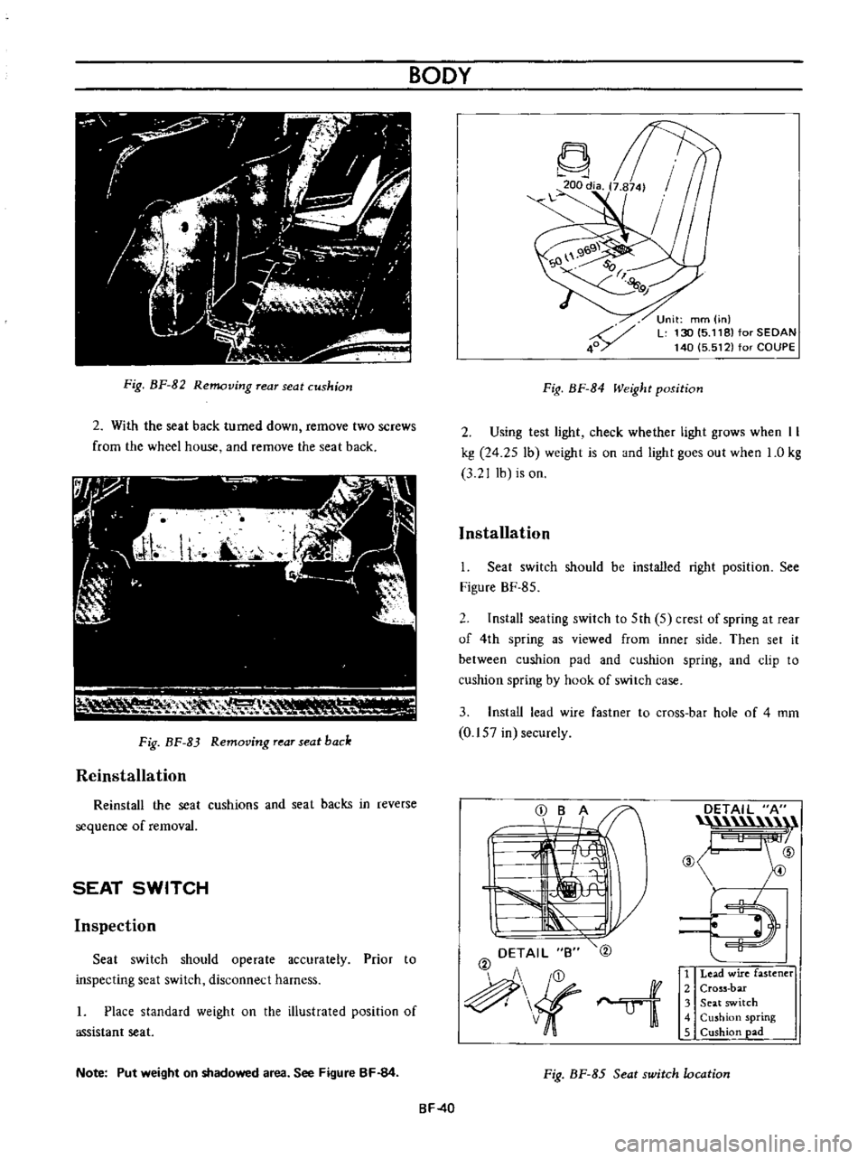
Fig
BF
82
Removing
rear
seat
cushion
2
With
the
seat
back
turned
down
remove
two
screws
from
the
wheel
house
and
remove
the
seat
back
111
I
V
RH
0
1
lr
Fig
BF
83
Removing
rear
seat
back
Reinstallation
Reinstall
the
seat
cushions
and
seat
backs
in
reverse
sequence
of
removal
SEAT
SWITCH
Inspection
Seat
switch
should
operate
accurately
Prior
to
inspecting
seat
switch
disconnect
harness
I
Place
standard
weight
on
the
illustrated
position
of
assistant
seat
Note
Put
weight
on
shadowed
area
See
Figure
BF
84
BODY
Fig
BF
84
Weight
position
Unit
mm
in
L
130
15
118
for
SEDAN
140
5
512
for
COUPE
2
Using
test
light
check
whether
light
grows
when
II
kg
24
25
lb
weight
is
on
and
light
goes
out
when
1
0
kg
3
2
J
lb
is
on
Installation
I
Seat
switch
should
be
installed
right
position
See
Figure
BF
85
2
Install
seating
switch
to
5th
5
crest
of
spring
at
rear
of
4th
spring
as
viewed
from
inner
side
Then
set
it
between
cushion
pad
and
cushion
spring
and
clip
to
cushion
spring
by
hook
of
switch
case
3
Install
lead
wire
fastner
to
cross
bar
hole
of
4
mm
0
157
in
securely
DETAIL
B
@
ui
DETAIL
A
n
@
ID
E
l
1
Lead
wire
fastener
2
Cross
bar
3
Seat
switch
4
Cushion
spring
5
Cushion
pad
Fig
BF
85
Seat
switch
location
BF
40
Page 282 of 513
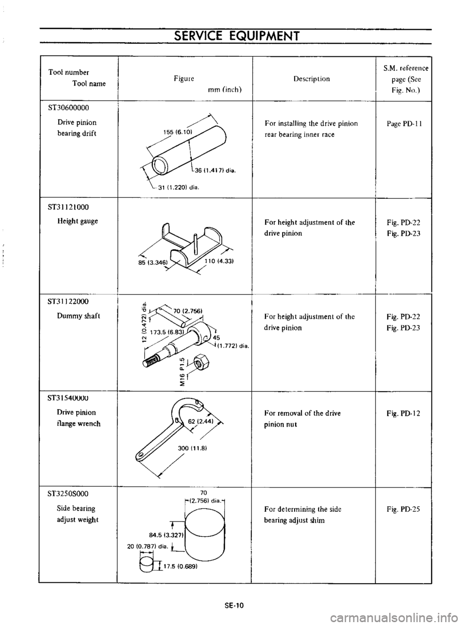
Tool
number
Tool
name
ST30600000
Drive
pinion
bearing
drift
ST31121000
Heigh
t
gauge
ST31122000
Dummy
shaft
ST3154llllUll
Drive
pinion
flange
wrench
ST3250S000
Side
bearing
adjust
weight
SERVICE
EQUIPMENT
Figure
mm
inch
15516
101
36114171dia
31
1
220
dia
70
2
756
cHa
r
84
513
271
20
O
Je7l
diil
L
9I17510Y
sE
lO
Description
For
installing
the
drive
pinion
rear
bearing
inner
race
For
height
adjustment
of
the
drive
pinion
For
height
adjustment
of
the
drive
pinion
For
removal
of
the
dri
ve
pinion
nut
For
determining
the
side
bearing
adjust
shim
S
M
reference
page
See
Fig
No
Page
PD
II
Fig
PD
22
Fig
PD
23
Fig
PD
22
Fig
PD
23
Fig
PD
12
Fig
PD
25
Page 286 of 513
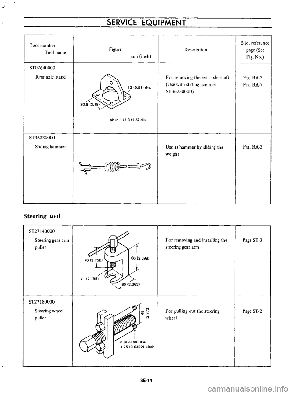
Tool
number
Tool
name
ST07640000
Rear
axle
stand
ST36230000
Sliding
hammer
Steering
tool
ST27140000
Steering
gear
arm
puller
ST27
I
80000
Steering
wheel
puller
SERVICE
EQUIPMENT
Figure
mm
inch
pitch
114
3
4
51
dia
J
l
VJJJJ1
P
J
SE
14
Description
For
removing
the
rear
axle
shaft
Use
with
sliding
hammer
ST36230000
Use
as
hammer
by
sliding
the
weight
For
removing
and
installIng
the
steering
gear
arm
For
pulling
out
the
steering
wheel
S
M
refelcTu
e
page
See
Fig
No
Fig
RA
3
Fig
RA
7
Fig
RA
3
Page
ST
3
Page
ST
2