1973 DATSUN B110 remote control
[x] Cancel search: remote controlPage 7 of 513
AUTOMATIC
TRANSMISSION
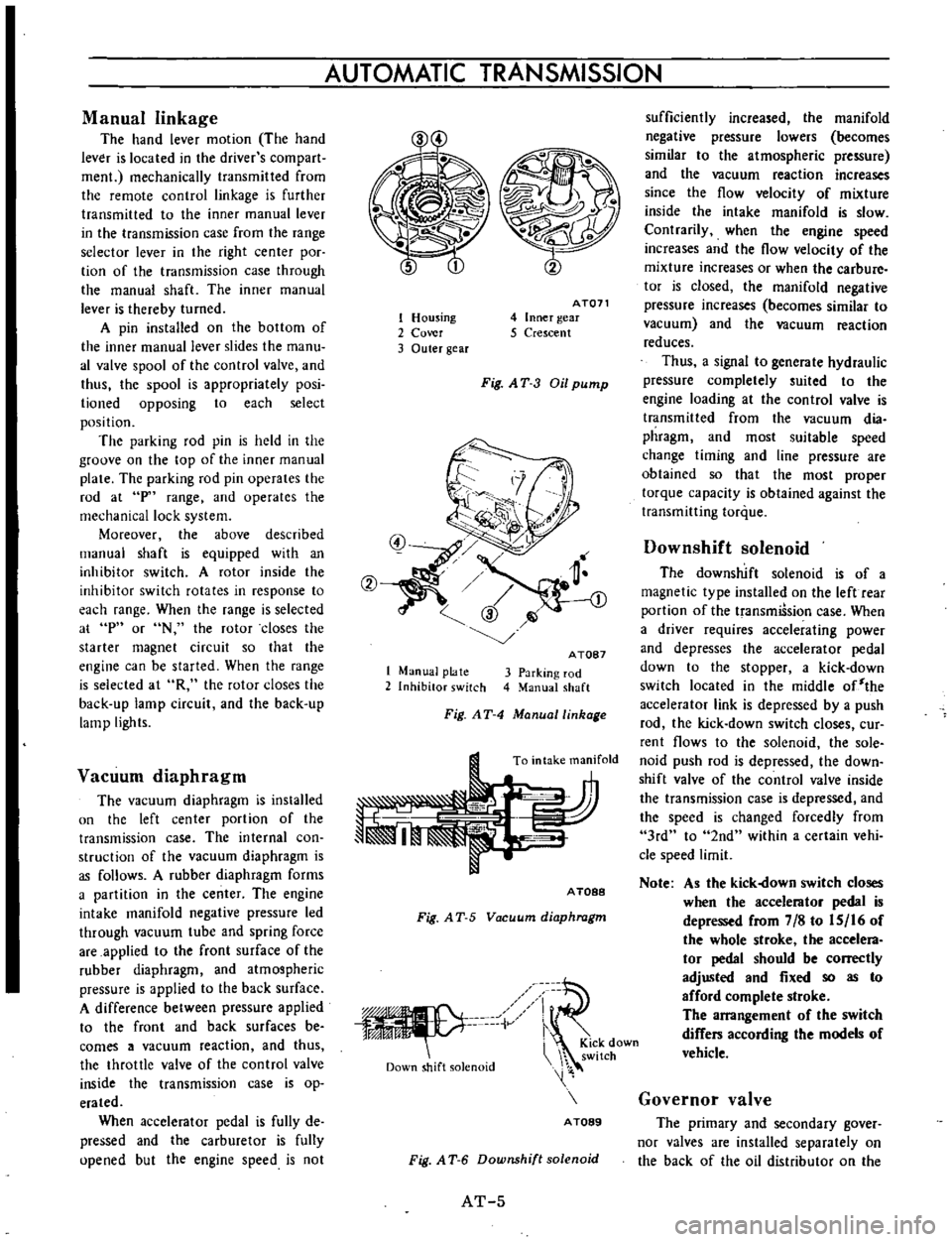
Manual
linkage
The
hand
lever
motion
The
hand
lever
is
located
in
the
driver
s
com
part
men
mechanically
transmitted
from
the
remote
control
linkage
is
further
transmitted
to
the
inner
manual
lever
in
the
transmission
case
from
the
range
selector
lever
in
the
right
center
poc
tion
of
the
transmission
case
through
the
manual
shaft
The
inner
manual
lever
is
thereby
turned
A
pin
installed
on
the
bottom
of
the
inner
manual
lever
slides
the
manu
al
valve
spool
of
the
control
valve
and
thus
the
spool
is
appropriately
posi
lioned
opposing
to
each
select
position
The
parking
rod
pin
is
held
in
the
groove
on
the
top
of
the
inner
manual
plate
The
parking
rod
pin
operates
the
rod
at
p
range
and
operates
the
mechanical
lock
system
Moreover
the
above
described
manual
shaft
is
equipped
with
an
inhibitor
switch
A
rotor
inside
the
inhibitor
switch
rotates
in
response
to
each
range
When
the
range
is
selected
at
p
or
N
the
rotor
closes
the
starter
magnet
circuit
so
that
the
engine
can
be
started
When
the
range
is
selected
at
R
the
rotor
closes
the
back
up
lamp
circuit
and
the
back
up
lamp
lights
Vacuum
diaphragm
The
vacuum
diaphragm
is
installed
un
the
left
center
portion
of
the
transmission
case
The
internal
con
struction
of
the
vacuum
diaphragm
is
as
follows
A
rubber
diaphragm
forms
a
partition
in
the
center
The
engine
intake
manifold
negative
pressure
led
through
vacuum
tube
and
spring
force
are
applied
to
the
front
surface
of
the
rubber
diaphragm
and
atmospheric
pressure
is
applied
to
the
back
surface
A
difference
between
pressure
applied
to
the
front
and
back
surfaces
be
comes
a
vacuum
reaction
and
thus
the
throttle
valve
of
the
control
valve
inside
the
transmission
case
is
op
erated
When
accelerator
pedal
is
fully
de
pressed
and
the
carburetor
is
fully
upened
but
the
engine
speed
is
not
1
Housing
2
Cover
3
Outer
gear
AT071
4
Inner
gear
5
Crescent
Fig
AT
3
Oil
pump
1
Manual
plate
2
Inhibitor
switch
A
TOB7
3
Parking
rod
4
Manual
shaft
Fig
AT
4
Manuallinhage
To
intake
manifold
A
TOBB
Fig
A
T
5
Vacuum
diaphragm
iV
Down
shift
solenoid
i
KiCk
down
switch
A
TOB9
Fig
A
T
6
Downshift
solenoid
AT
5
sufficiently
increased
the
manifold
negative
pressure
lowers
becomes
similar
to
the
atmospheric
pressure
and
the
vacuum
reaction
increases
since
the
flow
velocity
of
mixture
inside
the
intake
manifold
is
slow
Contrarily
when
the
engine
speed
increases
and
the
flow
velocity
of
the
mixture
increases
or
when
the
carbure
tor
is
closed
the
manifold
negative
pressure
increases
becomes
similar
to
vacuum
and
the
vacuum
reaction
reduces
Thus
a
signal
to
generate
hydraulic
pressure
completely
suited
to
the
engine
loading
at
the
control
valve
is
transmitted
from
the
vacuum
dia
phragm
and
most
suitable
speed
change
timing
and
line
pressure
are
obtained
so
that
the
most
proper
torque
capacity
is
obtained
against
the
transmitting
torque
Downshift
solenoid
The
downshift
solenoid
is
of
a
magnetic
type
installed
on
the
left
rear
portion
of
the
transmiSsion
case
When
a
driver
requires
accelerating
power
and
depresses
the
accelerator
pedal
down
to
the
stopper
a
kick
down
switch
located
in
the
middle
of
the
accelerator
link
is
depressed
by
a
push
rod
the
kick
down
switch
closes
cur
rent
flows
to
the
solenoid
the
sole
noid
push
rod
is
depressed
the
down
shift
valve
of
the
control
valve
inside
the
transmission
case
is
depressed
and
the
speed
is
changed
forcedly
from
3rd
to
2nd
within
a
certain
vehi
cle
speed
limit
Note
As
the
kick
own
switch
closes
when
the
accelerator
pedal
is
depressed
from
7
8
to
IS
16
of
the
whole
stroke
the
accelera
tor
pedal
should
be
correctly
adjusted
and
fixed
so
as
to
afford
complete
stroke
The
arrangement
of
the
switch
differs
according
the
models
of
vehicle
Governor
valve
The
primary
and
secondary
gover
nor
valves
are
installed
separately
on
the
back
of
the
oil
distributor
on
the
Page 218 of 513
IT
f
r
J
e
@
@
BODY
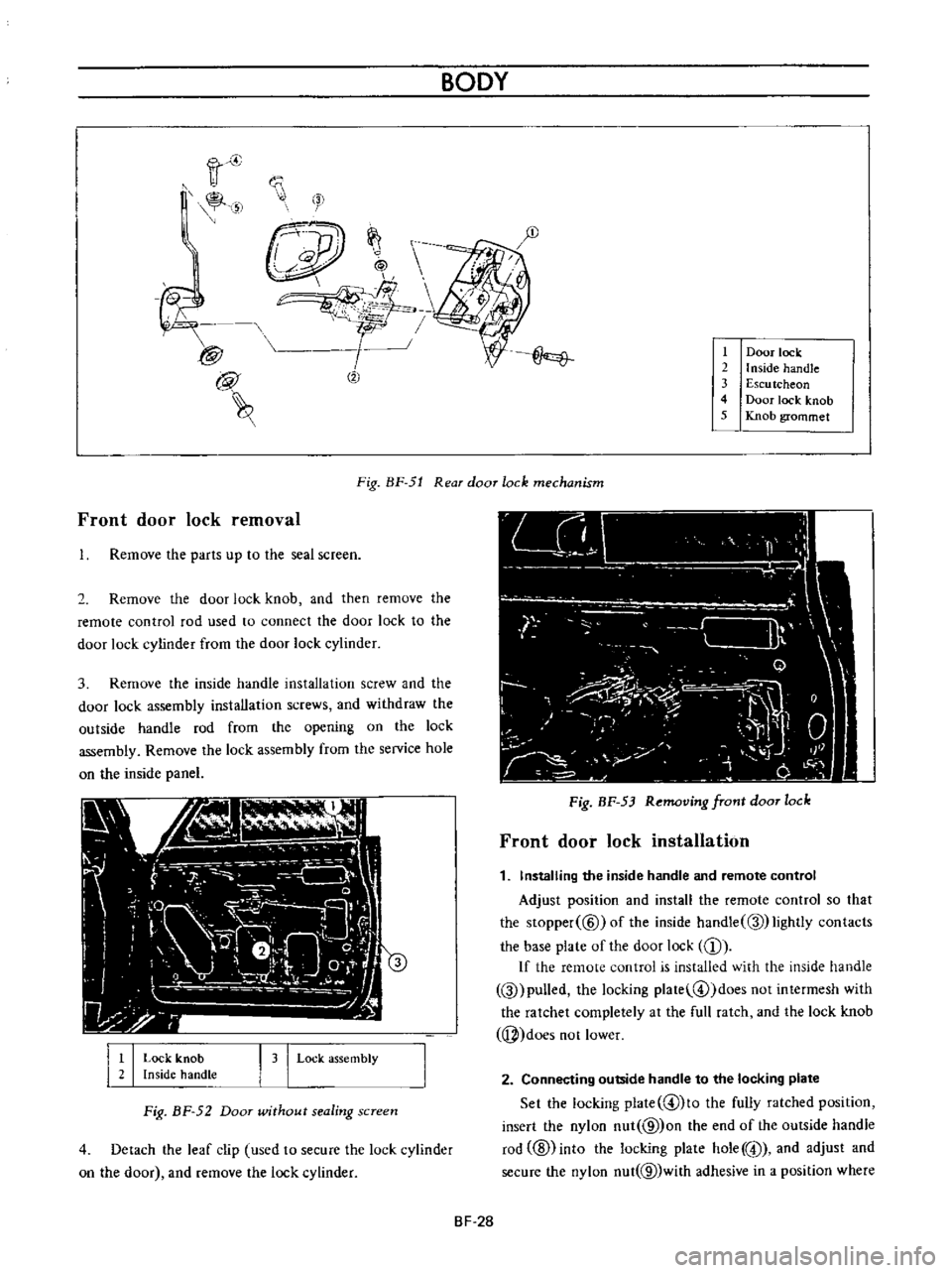
Door
lock
2
I
nside
handle
3
Escu
tcheon
4
Door
lock
knob
5
Knob
grommet
Front
door
lock
removal
Fig
BF
51
Rear
door
lock
mechanism
Remove
the
parts
up
to
the
seal
screen
2
Remove
the
door
lock
knob
and
then
remove
the
remote
control
rod
used
to
connect
the
door
lock
to
the
door
lock
cylinder
from
the
door
lock
cylinder
3
Remove
the
inside
handle
installation
screw
and
the
door
lock
assembly
installation
screws
and
withdraw
the
outside
handle
rod
from
the
opening
on
the
lock
assembly
Remove
the
lock
assembly
from
the
service
hole
on
the
inside
panel
I
I
Lock
knob
Inside
handLe
I
3
I
Lock
assembly
Fig
BF
52
Door
wUhout
sealing
screen
4
Detach
the
leaf
clip
used
to
secure
the
lock
cylinder
on
the
door
and
remove
the
lock
cylinder
Fig
BF
53
Removing
front
door
lock
Front
door
lock
installation
1
Installing
the
inside
handle
and
remote
control
Adjust
position
and
install
the
remote
control
so
that
the
Slopper
@
ofthe
inside
handle
Q
lightly
contacts
the
base
plate
of
the
door
lock
CD
If
the
remote
control
is
installed
with
the
inside
handle
Q
pulled
the
locking
plate
@
doesnotintermesh
with
the
ratchet
completely
at
the
full
ratch
and
the
lock
knob
j
does
not
lower
2
Connecting
outside
handle
to
the
locking
plate
Set
the
locking
plate
@lto
the
fully
ratched
position
insert
the
nylon
nut
@
on
the
end
of
the
outside
handle
rod
ID
into
the
locking
plate
hole
@
and
adjust
and
secure
the
nylon
nut
@
with
adhesive
in
a
position
where
BF
28
Page 219 of 513
the
outside
handle
rod
@
is
provided
with
2
to
3
mm
0
0787
to
0
1181
in
play
in
the
stroke
If
the
nylon
nut
@
is
positioned
too
low
the
locking
plate
@
is
depressed
at
the
full
ratch
the
locking
plate
does
not
intermesh
with
the
ratchet
completely
and
the
knob
cannot
be
locked
If
play
in
stroke
of
the
outside
handle
rod
@
is
excessive
may
be
unlocked
up
to
5
mm
0
1967
in
stroke
of
the
outside
handle
will
be
insufficient
If
the
nylon
nut
is
loosened
the
above
described
trouble
occurs
Be
sure
to
secure
the
nut
completely
by
means
of
adhesive
Check
the
springs
@
and
@
for
rust
and
replace
as
required
Tightening
torque
Door
lock
installation
screw
0
12
to
0
2
kg
m
0
9
to
I
4
ft
lb
Door
lock
remote
control
installation
screw
0
12
to
0
2
kg
m
0
9
to
14
ft
lb
Outside
handle
installation
nut
0
2
to
0
3
kg
m
1
4
to
2
2
ft
Ib
Rear
door
lock
removal
1
Remove
the
parts
up
to
the
seal
screen
2
Raise
the
door
glass
to
the
top
and
remove
the
door
DOOR
GLASS
AND
REGULATOR
i
v
BODY
lock
knob
3
Remove
the
bell
crank
installation
screw
Hereinafter
the
instructions
for
removal
of
the
front
door
lock
apply
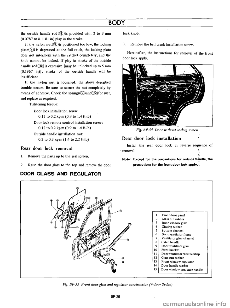
Fig
BF
54
Door
without
sealing
screen
Rear
door
lock
installation
Install
the
rear
door
lock
in
reverse
sequence
of
removal
Note
Except
for
the
precautions
for
outside
handle
the
precautions
for
the
front
door
lock
apply
AD
1
Front
door
panel
2
Glass
run
rubber
3
Door
window
glass
4
Glazing
rubber
5
Bottom
channel
6
Door
ventilator
frame
7
Ventilator
glass
channel
8
Catch
handle
9
Door
ventilator
glass
10
Pivot
bracket
11
Door
ventilator
weatherstrip
12
Glass
run
rubber
13
Front
window
regulator
14
Door
handle
washer
15
Door
window
regulator
handle
Fig
BF
55
Front
door
glass
and
regulator
construction
4
door
Sedan
SF
29
Page 468 of 513
ENGINE
REMOVAL
INSTAllATION
5
Disconnecting
clutch
wire
on
right
hand
drive
model
On
left
hand
drive
model
disconnect
hydraulic
line
from
the
clutch
slave
cylinder
Disconnect
the
clutch
wire
at
the
portion
of
the
withdrawal
lever
See
the
section
covering
the
clutch
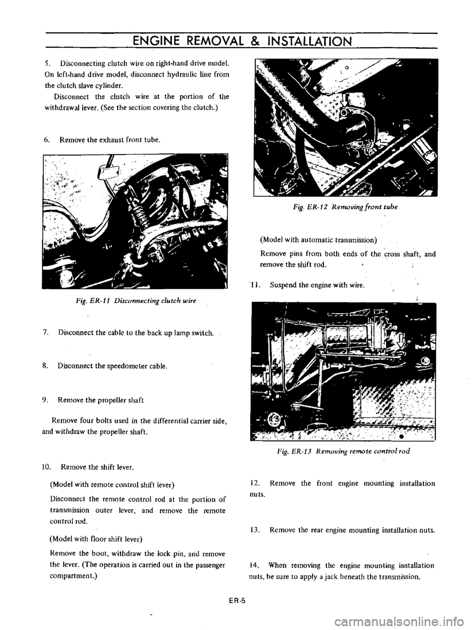
6
Remove
the
exhaust
front
tube
ij
f
I
Fig
ER
11
Disconnecting
dutch
wire
7
Disconnect
the
cable
to
the
back
up
lamp
switch
8
Disconnect
the
speedometer
cable
9
Remove
the
propeller
shaft
Remove
four
bolts
used
in
the
differential
carrier
side
and
withdraw
the
propeller
shaft
10
Remove
the
shift
lever
Model
with
remote
control
shift
lever
Disconnect
the
remote
control
rod
at
the
portion
of
transmission
outer
lever
and
remove
the
remote
control
rod
Model
with
floor
shift
lever
Remove
the
boot
withdraw
the
lock
pin
and
remove
the
lever
The
operation
is
carried
out
in
the
passenger
compartment
Fig
ER
12
Removing
fTont
tube
Model
with
automatic
transmission
Remove
pins
from
both
ends
of
the
cross
shaft
and
remove
the
shift
rod
II
Suspend
the
engine
with
wire
Fig
ER
13
Removing
remote
control
rod
12
Remove
the
front
engine
mounting
installation
nuts
13
Remove
the
rear
engine
mounting
installation
nuts
14
When
removing
the
engine
mounting
installation
nuts
be
sure
to
apply
a
jack
beneath
the
transmission
ER
5
Page 490 of 513
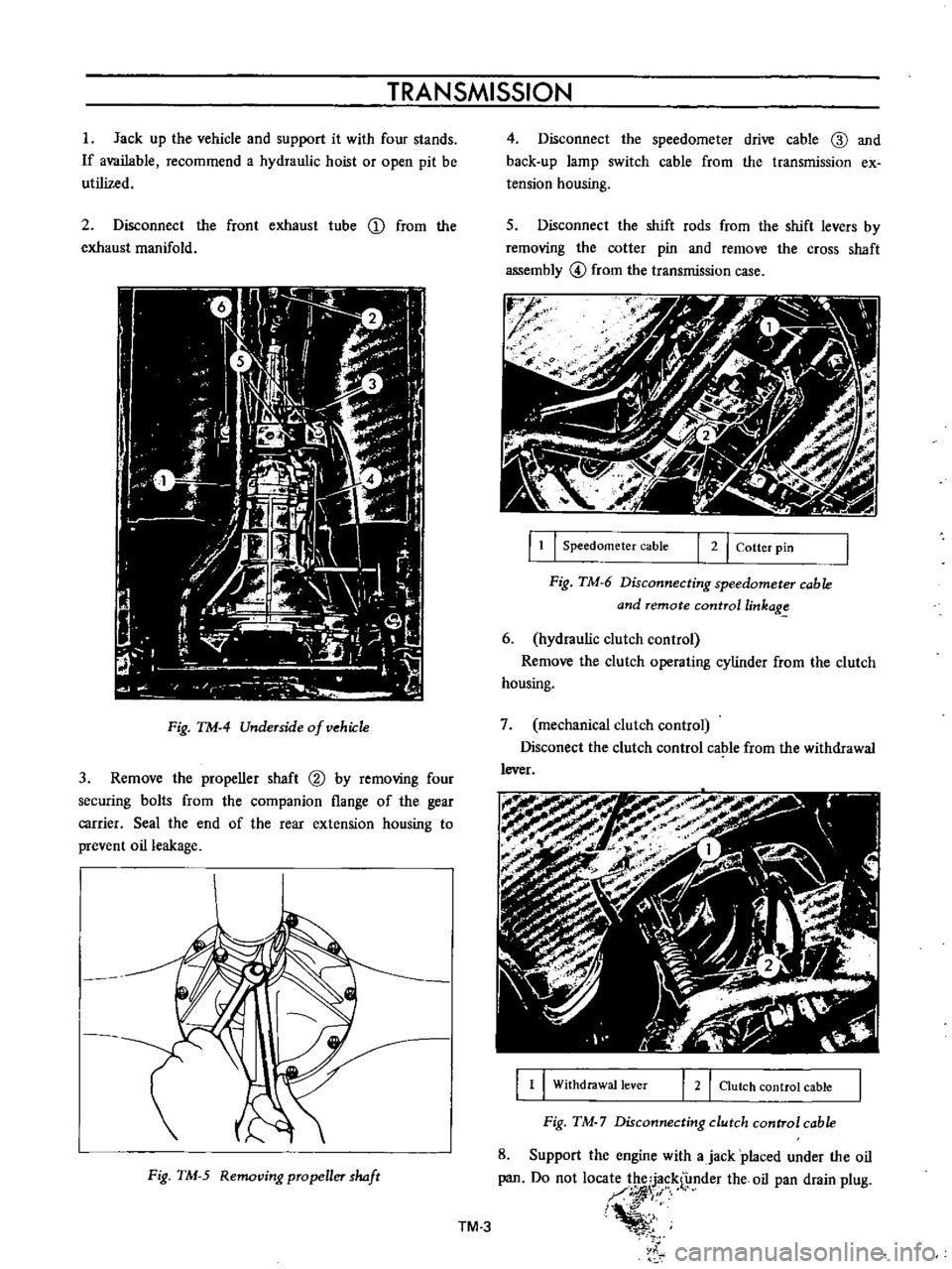
TRANSMISSION
I
Jack
up
the
vehicle
and
support
it
with
four
stands
If
available
recommend
a
hydraulic
hoist
or
open
pit
be
utilized
2
Disconnect
the
front
exhaust
tube
D
from
the
exhaust
manifold
Fig
TM
4
Underside
of
vehiJ
1e
3
Remove
the
propeller
shaft
@
by
removing
four
securing
bolts
from
the
companion
flange
of
the
gear
carrier
Seal
the
end
of
the
rear
extension
housing
to
prevent
oil
leakage
Fig
TM
5
Removing
propeller
haft
4
Disconnect
the
speedometer
drive
cable
ID
and
back
up
lamp
switch
cable
from
the
transmission
ex
tension
housing
s
Disconnect
the
shift
rods
from
the
shift
levers
by
removing
the
cotter
pin
and
remove
the
cross
shaft
assembly
@
from
the
transmission
case
r
J
f
f
1
I
Speedometer
cable
I
2
I
Cotter
pin
Fig
TM
6
Disconnecting
speedometer
cable
and
remote
controllinkag
6
hydraulic
clutch
control
Remove
the
clutch
operating
cylinder
from
the
clutch
housing
7
mechanical
clutch
control
Disconect
the
clutch
control
cable
from
the
withdrawal
lever
1
1
Withdrawal
lever
2
I
Clutch
control
cable
Fig
TM
7
Disconnecting
clutch
control
cable
8
Support
the
engine
with
ajack
placed
under
the
oil
pan
Do
not
loca
1
f
nder
the
oil
pan
drain
plug
I
i
l
TM
3
Page 503 of 513
CHASSIS
REINSTALLATION
Remount
the
transmission
in
reverse
sequence
of
dismounting
TRANSMISSION
GEAR
CONTROL
CONTENTS
DESCRIPTION
COLUMN
SHIFT
CONTROL
SYSTEM
Removal
TM
16
TM
17
TM
17
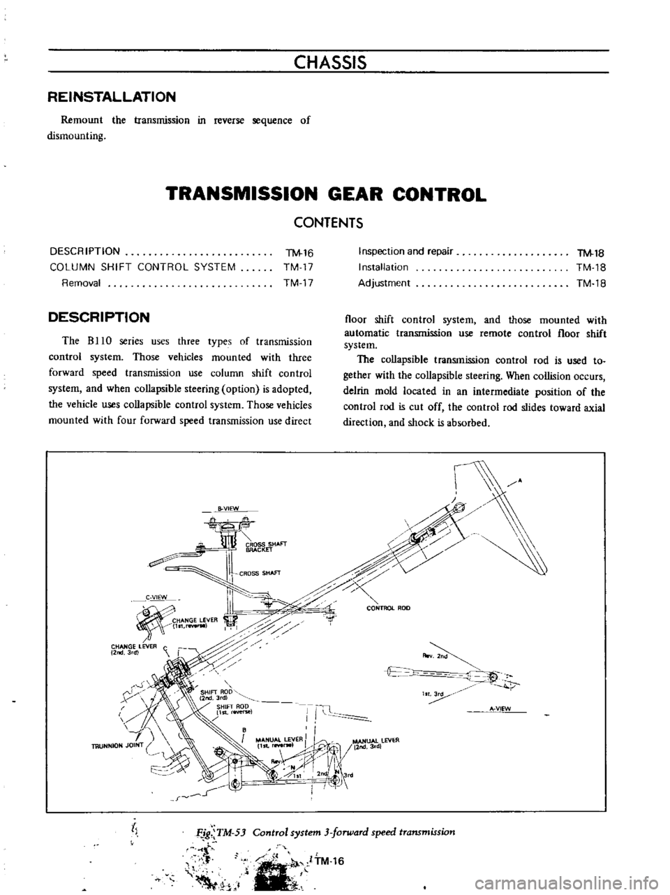
DESCRIPTION
The
B
10
series
uses
three
types
of
transmission
control
system
Those
vehicles
mounted
with
three
forward
speed
transmission
use
column
shift
control
system
and
when
collapsible
steering
option
is
adopted
the
vehicle
uses
collapsible
control
system
Those
vehicles
mounted
with
four
forward
speed
transmission
use
direct
B
VIEW
CROSS
SHAFT
BRACKET
CROSS
SHAfT
C
VIEW
HANGE
LEVER
l
rwIl
CHANGE
LEVER
C
2
3rdl
r
X
h
Inspection
and
repair
Installation
Adjustment
TM
18
TM
18
TM
18
floor
shift
control
system
and
those
mounted
with
automatic
transmission
use
remote
control
floor
shift
system
The
collapsible
transmission
control
rod
is
used
to
gether
with
the
collapsible
steering
When
collision
occurs
delrin
mold
located
in
an
intermediate
position
of
the
control
rod
is
cut
off
the
control
rod
slides
toward
axial
direction
and
shock
is
absorbed
c
0
CONTROL
ROD
r
A
v
t
c
t
IT
Ii
A
VIEW
MANUAL
LEVER
II
l
MANUAl
lEVER
11st
r
lW1
11nd3rd
IIooV
j
II
1
0SI
2nd
Jrd
I
I
j
tl
Control
system
3
forward
speed
transmission
Ffg
TM
53
t
f
Voo
1
ITM
16