1973 DATSUN B110 battery
[x] Cancel search: batteryPage 37 of 513

AUTOMATIC
TRANSMISSION
REMOVAL
AND
INSTAllATION
TRANSMISSION
ASSEMBLY
Removal
Installation
TRANSMISSION
ASSEMBLY
When
dismounting
the
automatic
transmission
from
a
vehicle
pay
at
tention
to
the
following
points
1
Before
dismounting
the
trans
mission
rigidly
inspect
it
by
aid
of
the
Troubleshooting
Chart
and
dis
mount
it
only
when
considered
to
be
necessary
2
Dismount
the
transmission
with
utmost
care
and
when
mounting
observe
the
tightening
torque
indi
cated
on
another
table
not
to
exert
excessive
force
Removal
In
dismounting
automatic
transmis
sion
from
vehicle
proceed
as
follows
i
Disconnect
battery
ground
cable
from
terminal
2
Jack
up
car
and
support
its
weight
on
safety
stands
Recommend
a
hydraulic
hoist
or
open
pit
be
utilized
if
available
Make
sure
that
safety
is
insured
3
Remove
propeller
shaft
Note
Plug
up
the
opening
in
the
rear
extension
to
prevent
oil
from
flowing
out
4
Disconnect
front
exhaust
tube
5
Disconnect
selector
range
lever
from
manual
shaft
6
Disconnect
wire
connections
at
inhibitor
switch
CONTENTS
AT
33
AT
33
AT
33
TRANSMISSION
CONTROL
LINKAGE
Removal
and
installation
Adjustment
AT
35
AT
36
AT
36
7
Disconnect
vacuum
tube
from
vacuum
diaphragm
and
wire
connec
tions
at
downshift
solenoid
8
Disconnect
speedometer
cable
from
rear
extension
9
Disconnect
oil
charging
pipe
10
Support
engine
by
locating
a
jack
under
oil
pan
with
a
wooden
block
used
between
oil
pan
and
jack
Support
transmission
by
means
of
3
transmission
jack
11
Detach
converter
housing
dust
cover
Remove
bolts
securing
torque
converter
to
drive
plate
See
Figure
AT
47
AT265
Fig
AT
47
Removing
torque
converter
attaching
bolt
Note
Before
removing
torque
con
verter
scribe
match
marks
on
two
parts
so
that
they
may
be
replaced
in
their
original
posi
tions
at
assembly
12
Disconnect
engine
moun
t
and
hand
lever
bracket
by
removing
two
2
rear
engine
mount
securing
bolts
and
two
2
crossmember
mounting
bolts
13
Remove
starter
motor
14
Remove
bolts
securing
transmis
sion
to
engine
After
removing
these
AT
33
bolts
support
engine
and
transmission
with
jack
and
lower
the
jack
gradually
until
transmission
can
be
removed
and
take
out
transmission
under
the
car
Note
Plug
up
the
opening
such
as
oil
charging
pipe
rear
extension
etc
Installation
Installation
of
automatic
transmis
sion
on
vehicle
is
reverse
order
of
removal
However
observe
the
follow
ing
installation
notes
Drive
plate
mnout
Turn
crankshaft
one
full
turn
and
measure
drive
plate
mnou
t
with
indi
cating
finger
of
a
dial
gauge
rested
against
plate
See
Figure
AT48
Replace
drive
plate
if
in
excess
of
0
5
mm
0
020
in
Maximum
allowable
mnout
0
3
mm
0
012
in
A
T266
Fig
A
T
48
Measuring
drive
plate
runout
2
Installation
of
torque
converter
Line
up
notch
in
torque
converter
with
that
in
oil
pump
Be
extremely
careful
not
to
cause
undue
stresses
in
parts
in
installing
torque
converter
See
Figure
A
T
49
Page 207 of 513

BODY
FRONT
FENDER
AND
FRONT
END
CONTENTS
FRONT
FENDER
Removal
FRONT
BUMPER
BF
17
BF
17
BF
18
FRONT
FENDER
i
RADIATOR
GRILLE
OUTSIDE
MIRROR
BF
18
BF18
1
Front
fender
2
Cowl
top
sealer
3
Front
fender
sealer
4
Cowl
top
5
Side
dash
board
6
Front
pillar
7
Front
bumper
8
Front
bumper
stay
9
Front
bumper
side
bracket
10
Bumper
side
bracket
shim
Removal
Fig
BF
27
Front
fender
and
front
end
components
I
Open
the
hood
disconnect
the
battery
terrninal
for
the
sake
of
safety
and
disconnect
wirings
for
the
head
lamp
and
side
marker
lamp
at
their
connecting
terminals
2
Remove
the
front
bumper
radiator
grille
and
radiator
grille
surround
3
Remove
the
sm
moulding
and
holding
the
fender
remove
it
Fig
BF
28
Removing
front
fender
I
BF
17
Page 232 of 513

BODY
INSTRUMENT
PANEL
CONTENTS
REMOVAL
BF
42
REMOVAL
Fig
BF
88
Removing
instrument
panel
Note
There
are
two
types
of
instrument
panel
square
type
and
round
type
However
both
of
them
are
removed
and
reinstalled
in
the
same
manner
Disconnect
the
battery
cable
at
the
battery
terminal
2
Disconnect
the
wiring
harness
connector
units
Disconnect
the
instrument
harness
from
the
engine
compartment
harness
Disconnect
the
instrument
harness
from
the
turn
signal
switch
Disconnect
the
instrument
harness
frorn
the
body
harness
Disconnect
the
instrumen
t
harness
connected
to
the
door
switch
stop
lamp
switch
flasher
unit
and
passing
light
relay
option
REINSTALLATION
BF
43
Note
When
disconnecting
the
wiring
harness
recom
mend
to
use
tags
for
identifying
their
relationship
3
Disconnect
cables
for
radio
antenna
and
speaker
4
Remove
the
package
tray
the
shell
cover
and
turn
signal
switch
Note
Work
may
be
carried
out
without
removing
die
steering
wheel
However
it
is
recommended
to
remove
the
steering
wheel
50
that
work
can
be
carried
out
more
easily
5
Disconnect
the
speedometer
cable
from
the
speedometer
unit
6
Disconnect
the
heater
control
cable
at
the
heater
side
Fig
BF
89
Removing
imtrument
panel
Ii
BF
42
Page 241 of 513

INSPECTION
Referring
to
the
wiring
diagram
check
the
wiring
harness
for
connection
with
electrical
equipment
and
connector
for
conned
ion
and
installation
When
checking
the
wiring
harness
note
the
following
matters
Connected
unit
should
not
be
loose
rusted
or
contaminated
2
Cable
insulator
cover
should
not
be
damaged
crack
ed
or
insulating
material
should
not
be
deteriorated
3
For
those
parts
which
are
grounded
through
the
installation
bolts
the
bolts
should
be
in
contact
with
the
body
completely
so
that
continuity
is
provided
in
between
the
body
and
bolts
4
Terminals
of
unit
through
which
current
flows
should
not
come
into
contact
with
other
metal
parts
5
No
erroneous
connection
should
be
present
DESCRIPTION
When
an
overcunent
exceeding
the
rated
amperage
flows
to
a
circuit
the
fuse
is
heated
and
melted
the
circuit
is
interrupted
and
thus
cables
and
electrical
equipment
are
protected
from
damaging
due
to
burning
or
damaging
is
limited
to
the
minimum
This
vehicle
is
equipped
with
six
fuses
and
one
fusible
link
The
fuses
are
located
in
the
fuse
box
and
used
to
protect
illumination
signal
and
other
systems
and
the
fusible
link
is
adopted
in
the
cable
between
the
battery
and
alternator
to
protect
the
charging
and
starting
circuits
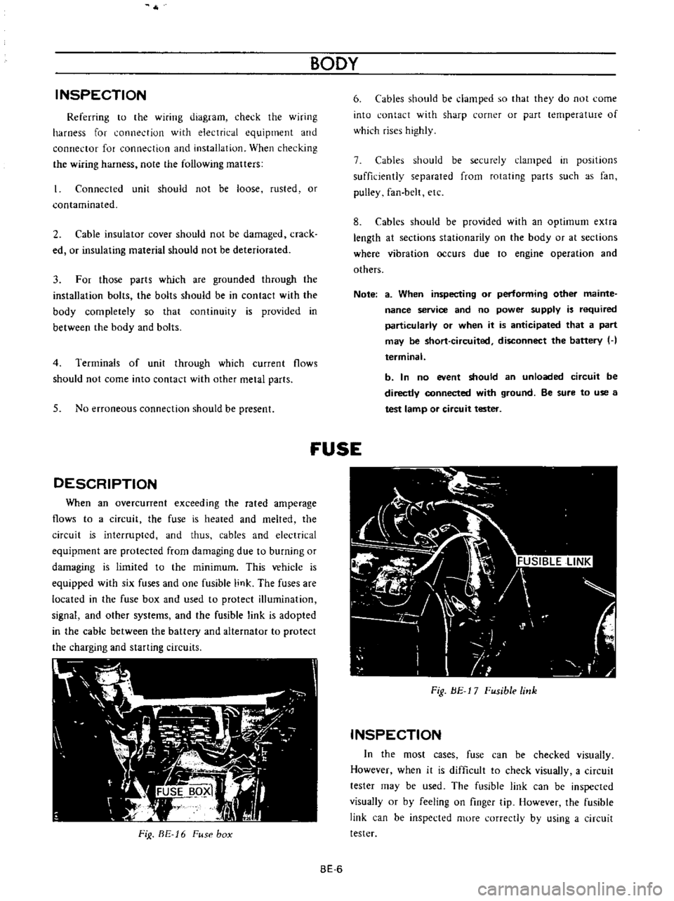
FiJ
BE
16
Fuse
box
BODY
6
Cables
should
be
damped
so
that
they
do
not
come
into
contact
with
sharp
corner
or
part
lernperature
of
which
rises
highly
7
Cables
should
be
securely
clamped
in
posItions
sufficiently
separated
from
rotating
parts
such
as
fan
pulley
fan
belt
etc
8
Cables
should
be
provided
with
an
optimum
extra
length
at
sections
stationarity
on
the
body
or
at
sections
where
vibration
occurs
due
to
engine
operation
and
others
Note
a
When
inspecting
or
performing
other
mainte
nance
service
and
no
power
supply
is
required
particularly
or
when
it
is
anticipated
that
a
part
may
be
short
circuited
disconnect
the
battery
H
terminal
b
In
no
event
should
an
unloaded
circuit
be
directly
connected
with
ground
Be
sure
to
use
a
test
lamp
or
circuit
tester
fUSE
Fig
BE
17
Fusible
link
INSPECTION
In
the
most
cases
fuse
can
be
checked
visually
However
when
it
is
difficult
to
check
visually
a
circuit
tester
may
be
used
The
fusible
link
can
be
inspected
visually
or
by
feeling
on
finger
tip
However
the
fusible
link
can
be
inspected
more
correctly
by
using
a
circuit
tester
BE
6
Page 248 of 513

BODY
ELECTRICAL
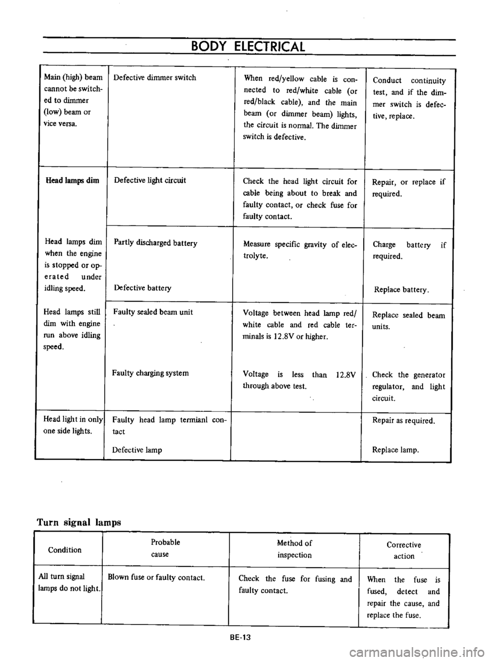
Main
high
beam
Defective
dimmer
switch
cannot
be
switch
ed
to
dimmer
low
beam
or
vice
versa
Head
lamps
dim
Defective
light
circuit
Head
lamps
dim
Partly
discharged
battery
when
the
engine
is
stopped
or
op
era
ted
under
idling
speed
Defective
battery
Head
lamps
still
Faulty
sealed
beam
unit
dim
with
engine
run
above
idling
speed
Faulty
charging
system
Head
light
in
only
one
side
lights
Faulty
head
lamp
terrnianl
con
tact
Defective
lamp
Turn
signal
lamps
Probable
Condition
cause
All
turn
signal
Blown
fuse
or
faulty
contact
lamps
do
not
light
When
red
yellow
cable
is
con
nected
to
red
white
cable
or
red
black
cable
and
the
main
beam
or
dimmer
beam
lights
the
circuit
is
nonnal
The
dimmer
switch
is
defective
Check
the
head
light
circuit
for
cable
being
about
to
break
and
faulty
contact
or
check
fuse
for
faulty
contact
Measure
specific
gravity
of
elec
trolyte
Voltage
between
head
lamp
red
white
cable
and
red
cable
ter
minals
is
12
8V
or
higher
Voltage
is
less
than
12
8V
through
above
test
Method
of
inspection
Check
the
fuse
for
fusing
and
faulty
contact
BE
13
Conduct
continuity
test
and
if
the
dirn
mer
switch
is
defec
tive
replace
Repair
or
replace
if
required
Charge
battery
if
required
Replace
battery
Replace
sealed
beam
units
Check
the
generator
regulator
and
light
circuit
Repair
as
required
Replace
lamp
Corrective
action
When
the
fuse
is
fused
detect
and
repair
the
cause
and
replace
the
fuse
Page 251 of 513

9HORN
r
I
01
8ATTERY
HI
IGI
s
ILl
C
iORN
BODY
FUSE
H
S
HORN
BUTTON
BGI
J
H
B
S
Il
I
n6lm
I
L
J
L
HORN
RELAY
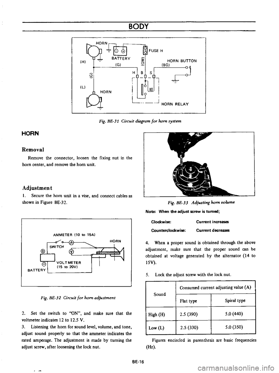
Fig
BE
3l
Circuit
diagram
for
hom
syrtem
HORN
Removal
Remove
the
connector
loosen
the
fixing
nut
in
the
horn
center
and
remove
the
horn
unit
Adjustment
1
Secure
the
horn
unit
in
a
vise
and
connect
cables
as
shown
in
Pigure
BE
32
AMMETER
110
to
15AI
Isw
f
@
113
I
VOLTMETER
I
15
to
20VI
BATTERY
HORN
Fig
BE
32
Circuit
for
ham
adjustment
2
Set
the
switch
to
ON
and
rnake
sure
that
the
voltmeter
indicates
12
to
12
5
V
3
Listening
the
horn
for
sound
level
volurne
and
tone
adjust
sound
properly
so
that
the
amrneter
indicates
the
rated
amperage
The
adjustment
is
made
by
turning
the
adjust
screw
after
loosening
the
lock
nut
Fig
BE
33
Adjusting
hom
IIOlume
Note
When
the
adjust
screw
is
turned
Clockwise
Counterclockwise
Current
increases
Current
decreases
4
When
a
proper
sound
is
obtained
through
the
above
adjustment
rnake
sure
that
the
proper
sound
can
be
obtained
at
voltage
generated
by
the
alternator
14
to
l5V
5
Lock
the
adjust
screw
with
the
lock
nut
Consumed
current
adjusting
value
A
Sound
Plat
type
Spiral
type
High
H
2
5
390
5
0
440
Low
L
2
5
330
5
0
350
Figures
encircled
in
parenthesis
are
basic
frequencies
Hz
BE
16
Page 252 of 513

BODY
ELECTRICAL
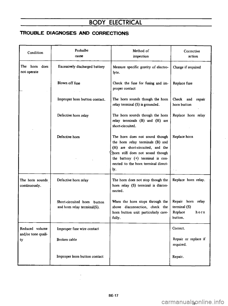
TROUBLE
DIAGNOSES
AND
CORRECTIONS
Condition
The
horn
does
not
operate
The
horn
sounds
continuously
Reduced
volume
and
or
tone
quali
ty
Probalbe
cause
Excessively
discharged
battery
Blown
off
fuse
Improper
horn
button
contact
Defective
horn
relay
Defective
horn
Defective
horn
relay
Short
circuited
horn
button
and
horn
relay
terminal
S
Improper
fuse
wire
contact
Broken
cable
Improper
horn
button
contact
Method
of
inspection
Measure
specific
gravity
of
electro
lyte
Corrective
action
Charge
if
required
Check
the
fuse
for
fusing
and
im
Replace
fuse
proper
contact
The
horn
sounds
though
the
horn
relay
terrninal
S
is
grounded
Check
and
repair
horn
button
The
horn
sounds
though
the
horn
Replace
horn
relay
relay
terrninals
B
and
H
are
short
circuited
The
horn
does
not
sound
though
Replace
horn
the
horn
relay
terminals
B
and
H
are
short
circuited
and
the
porn
still
does
not
sound
though
the
battery
terminal
is
con
nected
to
the
horn
terminal
direct
ly
The
horn
does
not
stop
though
the
Replace
horn
relay
horn
relay
S
terminal
is
discon
nected
When
the
horn
stops
through
the
above
disconnection
check
the
horn
button
unit
particularly
care
fully
BE
17
Repair
horn
relay
terminal
S
Replace
horn
button
Correct
Repair
or
replace
if
required
Repair
d
Page 253 of 513

BODY
METERS
AND
GAUGES
CONTENTS
CLUSTER
LID
Oescri
ption
Removal
SPEEDOMETER
Replacement
FUEL
GAUGE
AND
TEMPERATURE
GAUGE
Description
Replacement
BE
1B
BE
18
BE
18
BE
19
BE
19
BE
19
BE
19
BE
20
CLUSTER
LID
Description
The
cluster
lid
holds
various
rneters
indicators
and
clock
located
around
the
speedorneter
Printed
circuit
board
is
used
at
the
back
of
the
meter
as
shown
in
Figure
BE
38
and
the
printed
circuit
board
is
connected
with
multiple
connectors
Thus
the
meters
Can
be
inspected
and
serviced
extremely
easily
Except
for
the
speed
ometer
all
rneters
are
operated
electrically
The
fuel
gauge
and
therrnometer
are
very
reliable
and
they
are
equipped
with
bimetal
devices
F
a
o
ill
I
1
a
a
Fig
BE
34
Combination
meters
Removal
Disconnect
the
battery
terminal
depressing
the
OIL
PRESSURE
AND
IGNITION
WARNING
LAMPS
HAND
BRAKE
WARNING
LAMP
BULB
SPECIFICATIONS
TROUBLE
DIAGNOSES
AND
CORRECTIONS
Speedometer
Thermometer
and
fuel
meter
Oil
pressure
and
ignition
warning
lamps
BE
20
BE
21
BE
21
BE
22
BE
22
BE
23
BE
25
windshield
wiper
switch
lighting
switch
and
choke
lever
knobs
turn
them
counterclockwise
to
remove
Remove
the
escutcheon
2
Inserting
your
hand
into
back
of
the
cluster
lid
disconnect
the
cigarette
lighter
cable
and
turn
and
remove
the
cigarette
lighter
outer
case
3
Remove
the
radio
and
heater
control
knobs
4
Remove
the
shell
cover
from
the
steering
tube
loosen
the
screws
used
to
secure
the
meter
housing
to
the
instrument
panel
and
remove
the
cluster
lid
5
Pull
out
the
l2
pole
round
shape
connector
and
remove
the
speedometer
cable
union
nut
6
Remove
the
cluster
lid
from
the
instrument
panel
Fig
BE
35
Removing
clllSter
jd
BE
18