1973 DATSUN B110 battery
[x] Cancel search: batteryPage 261 of 513

The
lamp
does
not
go
out
when
the
engine
is
started
Faulty
charging
system
BODY
Inspect
the
charging
system
WINDSHIELD
WIPER
AND
WASHER
Description
Wiper
motor
replacement
Wiper
blade
operating
range
CONTENTS
BE
26
BE
27
BE
27
Description
The
windshield
wipers
consist
of
wiper
motor
link
mechanism
wiper
arms
and
blades
The
wiper
motor
unit
consists
of
a
motor
and
auto
stop
mechanism
The
wiper
rnotor
is
of
a
2
speed
type
When
the
wiper
switch
knob
is
pulled
to
the
I
st
step
the
windshield
wipers
operate
at
low
speed
and
when
pulled
to
the
2nd
step
operate
at
high
speed
The
wiper
motor
unit
is
located
on
the
cowl
dash
in
BATTERY
Cl
WIPER
MOTOR
rrQ
J
WASHER
MOTOR
IB
ILRI
L
CJ
LA
t
Y
I
Ll
j
IBI
1
f
I
LW
I
Wiper
washer
switch
replacement
Washer
nozzle
adjustment
TROUBLE
OIAGNOSES
ANO
CORRECTIONS
BE
27
BE
27
BE
28
the
engine
compartment
and
the
link
mechanism
is
located
behind
the
instrument
panel
The
electrically
operated
windshield
washer
consists
of
washing
fluid
lank
with
rnotor
and
pump
washer
nozzles
and
vinyl
tube
used
to
connect
those
compo
nents
The
windshield
washer
switch
is
combined
with
the
windshield
wiper
switch
to
a
single
unit
When
operating
the
washer
twist
the
switch
knob
IG
FUSE
W
v
l
i
f
WIPER
SWITCH
10FFI
I
2
I
TWIST
I
y
ILl
I
b
I
J
6
I
BLII
Fig
BE
43
Circuit
diagram
for
windshield
wiper
washer
system
BE
26
Page 265 of 513
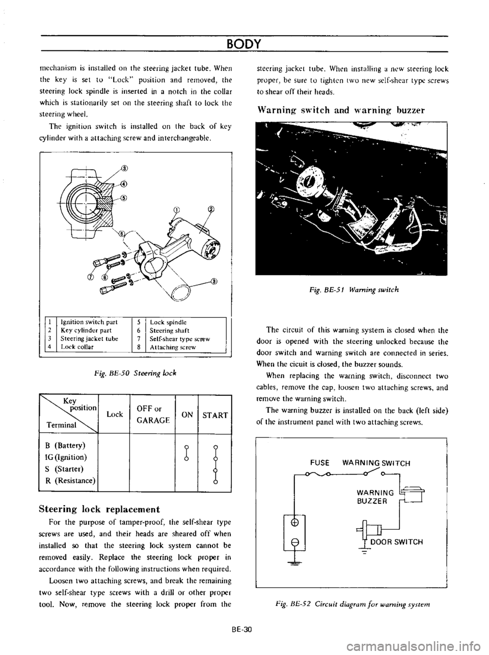
mechanism
is
installed
on
the
steering
jacket
tube
When
the
key
is
set
to
Lock
position
and
removed
the
steering
lock
spindle
is
inserted
in
a
notch
in
the
collar
which
is
stationarity
set
on
the
steering
shaft
to
lock
the
steering
wheel
The
ignitiun
switch
is
installed
on
the
back
of
key
cylinder
with
a
attaching
screw
and
interchangeable
tf
iY
t
7
a
1
Ignition
switch
part
2
Key
cylinder
part
3
Steering
jacket
tube
4
Lock
collar
5
Lock
pindle
6
Steering
shaft
7
Self
shear
type
screw
8
Attaching
screw
Fig
BE
50
Steering
lock
Key
position
Terminal
OFFor
GARAGE
Lock
ON
ST
ART
B
Battery
IG
Ignition
S
Starter
R
Resistance
b
1
Steering
lock
replacement
For
the
purpuse
of
tamper
proof
the
self
shear
type
screws
are
used
and
their
heads
are
sheared
off
when
installed
so
that
the
steering
lock
system
cannot
be
removed
easily
Replace
the
steering
lock
proper
in
accordance
with
the
following
instructions
when
required
Loosen
two
attaching
screws
and
break
the
remaining
twu
self
shear
type
screws
with
a
drill
or
other
proper
tool
Now
remove
the
steering
lock
proper
from
the
BODY
BE
30
steering
jacket
tube
When
installing
a
new
steering
lock
proper
be
sure
tu
tighten
two
new
self
shear
type
screws
to
shear
off
their
heads
Warning
switch
and
warnmg
buzzer
Fig
BE
51
Warning
switch
The
circuit
of
this
warning
system
is
closed
when
the
door
is
opened
with
the
steering
unlocked
because
the
door
switch
and
warning
switch
are
connected
in
series
When
the
cicuit
is
closed
the
buzzer
sounds
When
replacing
the
warning
switch
disconnect
two
cables
remove
the
cap
loosen
two
attaching
screws
and
remove
the
warning
switch
The
warning
buzzer
is
installed
on
the
back
left
side
of
the
instrument
panel
with
two
attaching
screws
FUSE
WARNING
SWITCH
WARN
BUZZ
G
n
WITCH
t
Fig
BE
52
Circuit
diagram
for
warning
system
Page 306 of 513

EMISSION
CONTROL
AND
TUNE
UP
EMISSION
CONTROL
SYSTEM
AN
D
ENGINE
TUNE
UP
CONTENTS
BASIC
MECHANICAL
SYSTEM
ET
Checking
and
adjusting
dash
pot
Adjusting
intake
and
exhaust
valve
automatic
transmission
model
only
ET
9
clearances
ET
1
Checking
carburetor
return
spring
ET
9
Checking
and
adjustin9
drive
belt
ET
2
Checking
choke
mechanism
choke
valve
Retightening
cylinder
head
bolts
manifold
and
linkagel
ET
9
nuts
and
carburetor
securing
nuts
ET
2
Checking
anti
dieseling
solenoid
ET
9
Checking
engine
oil
ET
2
Replacing
fuel
filter
ET
10
Replacing
oil
filter
ET
3
Checking
fuel
lines
hoses
pipings
Changing
engine
coolant
L
L
C
ET
3
connections
etc
ET10
Checking
cooling
system
hoses
and
THROTTLE
OPENER
CONTROL
SYSTEM
ET
10
connections
ET
4
Checking
and
adjusting
throttle
opener
ET
13
Checking
vacuum
fittings
hoses
and
TRANSMISSION
CONTROLLED
VACUUM
connections
ET
4
ADVANCE
SYSTEM
ET
17
Checking
engine
compression
ET
4
Checking
electrical
advance
control
system
ET
19
Checking
exhaust
manifold
heat
control
AUTOMATIC
TEMPERATURE
CONTROL
AIR
valve
ET
5
CLEANER
A
T
C
AIR
CLEANER
ET
20
IGNITION
AND
FUEL
SYSTEM
ET
5
Replacing
carburetor
air
cleaner
filter
ET
20
Checking
battery
ET
5
Checking
hot
air
control
valve
ET
20
Checking
and
adjusting
ignition
timing
ET
5
CRANKCASE
EMISSION
CONTROL
Checking
or
replacing
distributor
breaker
SYSTEM
ET
22
point
condenser
and
spark
plugs
ET
6
Checking
or
replacing
PCV
valve
ET
23
Checking
distributor
ignition
wiring
and
Checking
ventilation
hoses
ET
23
ignition
coil
ET
7
EVAPORATIVE
EMISSION
CONTROL
Checking
distributor
cap
and
rotor
ET
7
SYSTEM
ET
23
Adjusting
carburetor
id
Ie
rpm
and
Checking
engine
compartment
hose
mixture
ratio
ET
8
connections
and
fuel
vapor
control
valves
ET
23
Checking
fuel
tank
vacuum
relief
valve
operation
ET
24
BASIC
MECHANICAL
SYSTEM
1
Start
engine
and
run
it
until
it
is
heated
to
operating
temperature
or
at
least
more
than
800C
I760F
of
engine
oil
temperature
then
stop
engine
Adjusting
intake
and
exhaust
valve
clearances
Valve
clearance
adjustment
should
be
made
while
engine
is
stationary
To
adjust
proceed
as
follows
2
Rotate
crankshaft
to
bring
No
1
cylinder
in
top
dead
center
on
its
compression
stroke
3
Remove
valve
rocker
cover
to
gain
access
to
valve
ET
1
Page 310 of 513

EMISSION
CONTROL
AND
TUNE
UP
reading
cylinders
through
spark
plug
hole
Repeat
compression
check
on
these
cylinders
1
If
compression
improves
considerably
piston
rings
are
defective
2
If
compression
does
not
improve
valves
are
sticking
or
seating
improperly
3
If
two
adjacent
cylinders
indicate
low
compression
and
injecting
oil
on
pistons
does
not
increase
compres
sion
the
cause
may
be
a
cylinder
head
gasket
leak
between
the
cylinders
Engine
oil
and
coolant
in
cylinder
could
result
from
this
problem
Compression
pressure
12
S
to
14
S
kg
cm2
178
to
206
psi
at
3S0
rpm
Checking
exhaust
manifold
heat
control
valve
Check
heat
control
valve
for
proper
operation
If
it
does
not
operate
properly
trouble
is
due
to
excess
carbon
on
shaft
or
damaged
shaft
Clean
if
necessary
The
bimetal
should
be
also
checked
for
proper
function
IGNITION
AND
FUEL
SYSTEM
Checking
battery
Check
electrolyte
level
in
each
battery
celL
L
Unscrew
each
filler
cap
and
inspect
fluid
leveL
If
fluid
level
is
low
add
distilled
water
to
bring
level
up
to
app
roximately
10
to
20
mm
0
3937
to
0
7874
in
above
plates
Do
not
overfilL
2
Measure
specific
gravity
of
battery
electrolyte
ET002
Fig
ET
B
Checking
the
specific
gravity
of
battery
electrolyte
Permissible
Full
charge
value
value
at
200C
68OF
Frigid
climates
Over
1
22
1
28
Tropical
climates
Over
1
18
1
23
Other
climates
Over
L
20
1
26
Clean
the
top
of
battery
and
terminals
with
a
solu
lion
of
baking
soda
and
water
Rinse
off
and
dry
with
compressed
air
The
top
of
battery
must
be
clean
to
prevent
current
leakage
between
terminals
and
from
positive
terminal
to
hold
down
clamp
In
addition
to
current
leakage
prolonged
accumulation
of
acid
and
dirt
on
the
top
of
battery
may
cause
blistering
of
the
material
covering
connector
straps
and
corrosion
of
straps
After
tightening
terminals
coat
them
with
petro
laturn
vaseline
to
protect
them
from
corrosion
Checking
and
adjusting
ignition
timing
I
Check
spark
plugs
and
distributor
breaker
points
for
condition
2
Thoroughly
wipe
off
dirt
and
dust
from
timing
marks
on
crank
pulley
and
front
cover
3
Warm
up
engine
sufficiently
ET
5
Page 316 of 513
EMISSION
CONTROL
AND
TUNE
UP
Ignition
switch
0
Speed
switch
Ignition
switch
6
Transmission
A12
Engine
with
Manual
Transmission
l
Battery
J
Below
10
mph
switch
ON
To
throttle
opener
Servo
diaphragm
Needle
valve
To
air
cleaner
To
intake
manifold
f
Vacuum
control
valve
p
Throttle
opener
noid
ON
Car
speed
below
16
km
h
10
MPH
OFF
Car
speed
above
16
km
h
10
MPH
A12
Engine
with
Automatic
Transmission
Inhibitor
switch
1
J
Battery
To
intake
manifold
t
ET
11
OFF
ON
Fig
BY
16
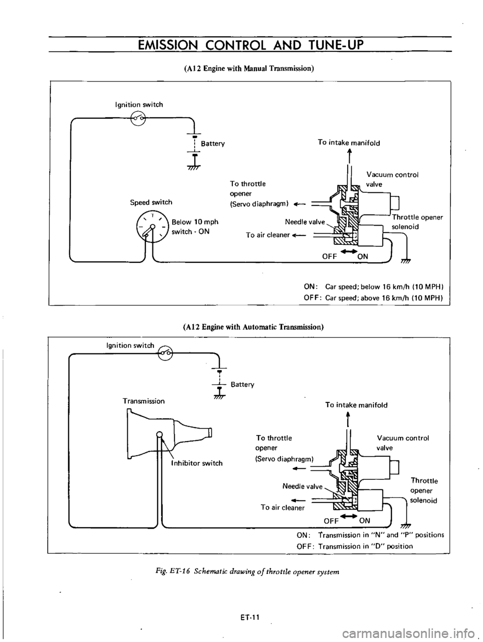
Schematic
drawing
of
throttle
opener
system
To
throttle
opener
Servo
diaphragm
Vacuum
control
valve
P
Throttle
t
opener
solenoid
7
7
ON
transmission
in
N
and
P
positions
OFF
Transmission
in
0
position
Page 323 of 513
ENGINE
Gear
Vacuum
advance
Note
R
No
1st
No
2nd
No
3rd
No
4th
Yes
Immediately
after
starting
the
engine
in
cold
weather
vacuum
advance
is
available
for
all
gear
positions
A12
Engine
with
Manual
Transmission
Distributor
Ignition
switch
8
1
J
Battery
Thermo
switch
9
Transmission
L
r
l
r
Vacuum
advance
unit
To
carburetor
Needle
valve
OFF
l
To
air
cleaner
ON
Vacuum
cutting
valve
solenoid
Top
switch
Top
off
I
7
1
OFF
Vacuum
actuated
ON
Vacuum
eminated
into
atmosphere
Fig
ET
28
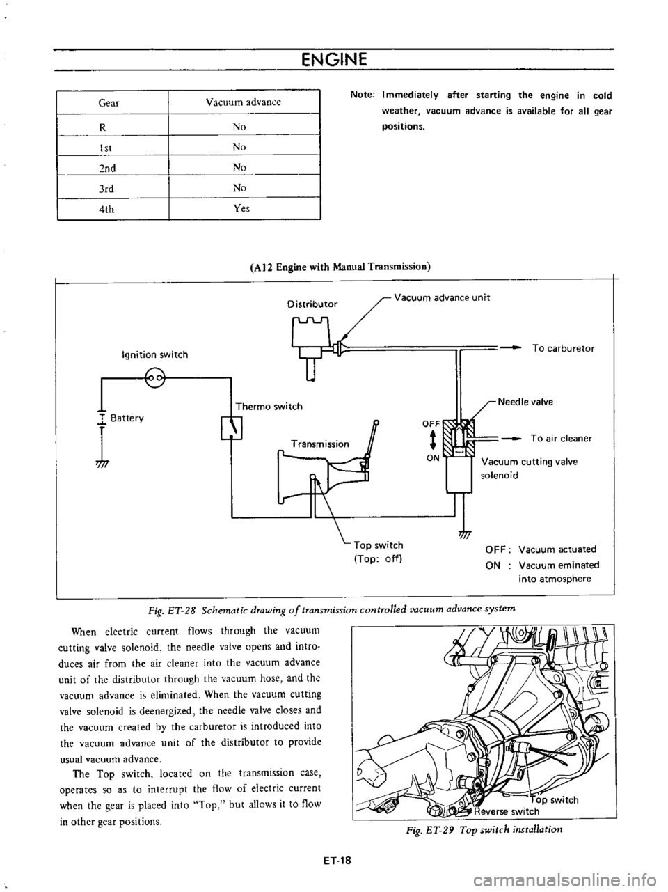
Schematic
drawing
of
transmission
controlled
vacuum
advance
system
When
electric
current
flows
through
the
vacuum
cutting
valve
solenoid
the
needle
valve
opens
and
intro
duces
air
from
the
air
cleaner
into
the
vacuum
advance
unit
of
the
distributor
through
the
vacuum
hose
and
the
vacuum
advance
is
eliminated
When
the
vacuum
cutting
valve
solenoid
is
deenergized
the
needle
valve
closes
and
the
vacuum
created
by
the
carburetor
is
introduced
into
the
vacuum
advance
unit
of
the
distributor
to
provide
usual
vacuum
advance
The
Top
switch
located
on
the
transmission
case
operates
so
as
to
interrupt
the
flow
of
electric
current
when
the
gear
is
placed
into
Top
but
allows
it
to
flow
in
other
gear
positions
Fig
ET
29
Top
switch
installation
ET
18
Page 330 of 513
EMISSION
CONTROL
AND
TUNE
UP
SERVICE
DATA
AND
SPECIFICATIONS
Valve
clearance
Hot
Intake
Exhaust
mm
in
rom
in
rom
in
kg
lb
0
35
0
014
0
35
0
014
10
to
15
0
394
to
0
591
10
22
Fan
belt
tension
Tightening
torque
Cold
Cylinder
head
bolts
kg
m
ft
lb
1st
turn
2nd
turn
Re
tightening
torque
Hot
Manifold
nuts
Carburetor
nuts
4
0
to
4
5
29
to
33
5
5
to
6
0
40
to
43
6
0
to
6
5
43
to
47
0
9
to
I
4
6
5
to
10
0
5
to
1
0
3
6
to
7
2
1
5
to
2
0
II
to
14
Spark
plugs
Oil
capacity
of
engine
including
oil
ftIter
Maximum
L
US
gal
Imp
gal
L
US
gal
Imp
gal
3
3
U
14
2
3
Ii
Minimum
Water
capacity
of
cooling
system
Without
heater
L
US
gal
Imp
gal
With
heater
L
US
gal
Imp
gal
4
2
1
U
4
9
I
4
11
12
5
to
14
5
I78
to
206
350
Compression
pressure
at
rpm
kg
em
psi
Battery
specific
gravity
Permissible
value
Fully
charged
value
at
200C
680F
Frigid
climates
Tropical
climates
Other
elima
tes
Over
1
22
Over
1
18
Over
1
20
1
28
1
23
1
26
Ignition
timing
degree
Distributor
50
B
T
D
C
Condenser
capacity
mm
in
degrees
IlF
Micro
Farad
0
45
to
0
55
0
018
to
0
022
49
to
55
0
22
5
Point
gap
Dwell
angle
Condenser
insulation
resistance
Mil
Mega
ohms
ET
25
Page 331 of 513
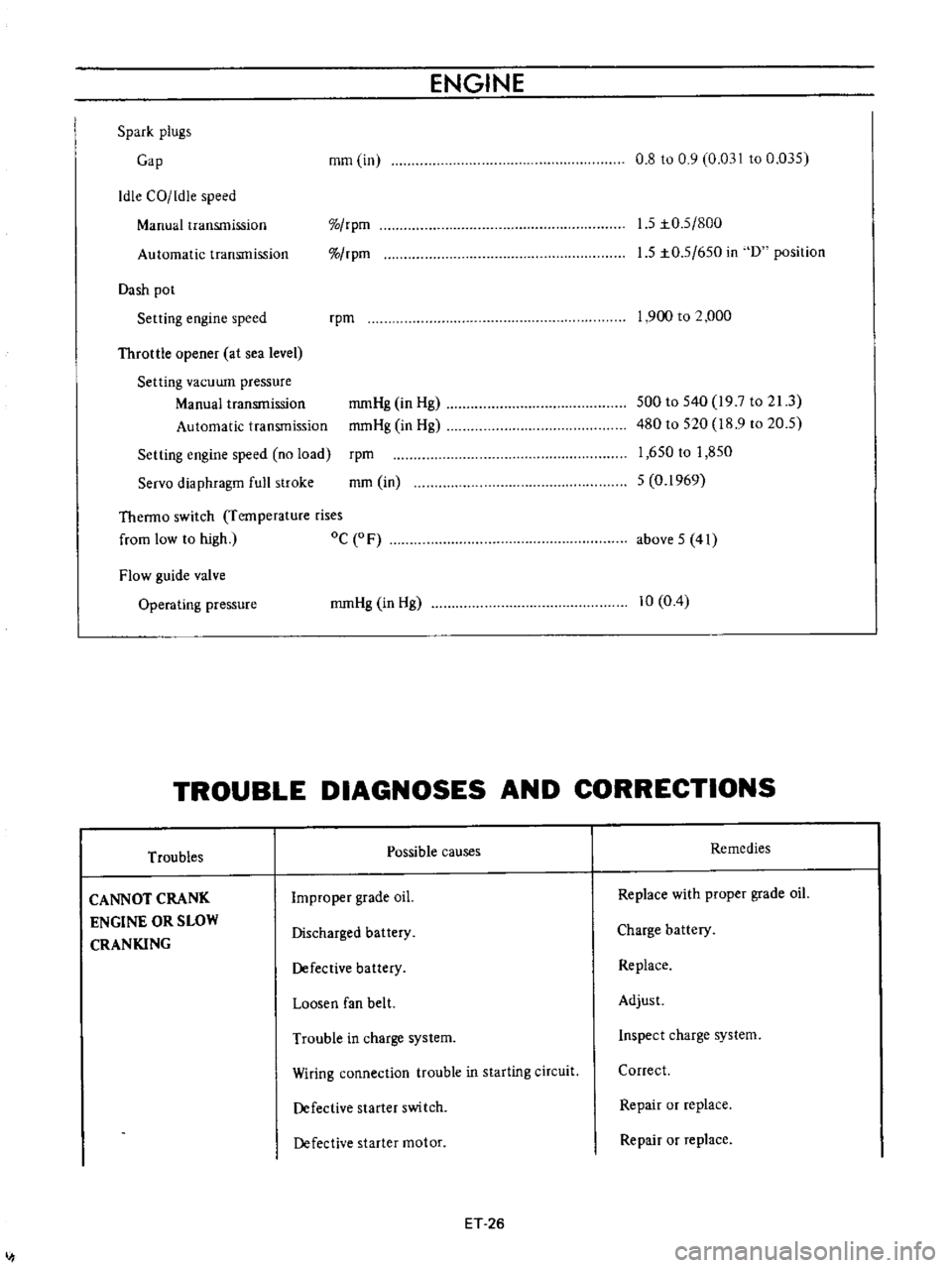
ENGINE
Spark
plugs
Cap
mm
in
0
8
to
0
9
0
03110
0
035
Idle
CO
ldie
speed
Manual
transmission
rpm
rpm
1
5
to
5
800
1
5
to
5
650
in
D
position
Automatic
transmission
Dash
pot
Setting
engine
speed
rpm
1
900
to
2
000
Throttle
opener
at
sea
level
Setting
vacuwn
pressure
Manual
transmission
Automatic
transmission
Setting
engine
speed
no
load
Servo
diaphragm
full
stroke
rpm
mm
in
500
to
540
19
7
to
21
3
480
to
520
18
9
to
20
5
1
650
to
1
850
5
0
1969
mmHg
in
Hg
mmHg
in
Hg
Theono
switch
Temperature
rises
from
low
to
high
oC
0
F
above
5
41
Flow
guide
valve
Opera
ting
pressure
mmHg
in
Hg
10
0
4
TROUBLE
DIAGNOSES
AND
CORRECTIONS
Troubles
Possible
causes
Remedies
CANNOT
CRANK
ENGINE
OR
SLOW
CRANKING
Improper
grade
oiL
Replace
with
proper
grade
oiL
Discharged
battery
Charge
battery
Defective
battery
Replace
Loosen
fan
belt
Adjust
Trouble
in
charge
system
Inspect
charge
system
Wiring
connection
trouble
in
starting
circuit
Correct
Defective
starter
switch
Repair
or
replace
Defective
starter
motor
Repair
or
replace
ET
26
I