1973 DATSUN B110 fuel type
[x] Cancel search: fuel typePage 315 of 513
ENGINE
Replacing
fuel
filter
Check
for
a
contamination
element
water
deposit
and
defection
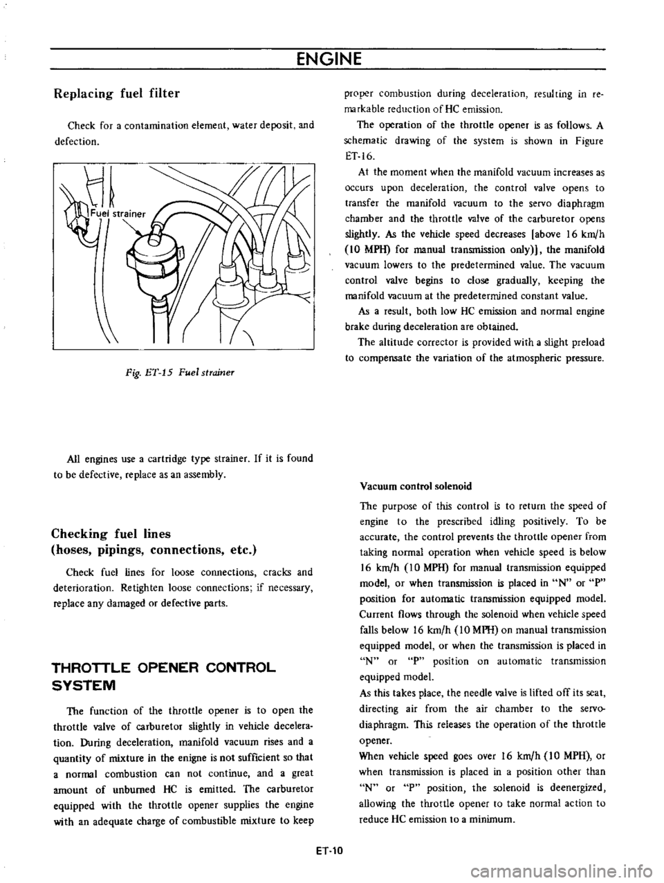
Fig
ET
15
Fuel
strcrineT
All
engines
use
a
cartridge
type
strainer
If
it
is
found
to
be
defective
replace
as
an
assembly
Checking
fuel
lines
hoses
pipings
connections
etc
Check
fuel
lines
for
loose
connections
cracks
and
deterioration
Retighten
loose
connections
if
necessary
replace
any
damaged
or
defective
parts
THROTTLE
OPENER
CONTROL
SYSTEM
The
function
of
the
throttle
opener
is
to
open
the
throttle
valve
of
carburetor
slightly
in
vehicle
decelera
tion
During
deceleration
manifold
vacuum
rises
and
a
quantity
of
mixture
in
the
enigne
is
not
sufficient
so
that
a
normal
combustion
can
not
continue
and
a
great
amount
of
unburned
HC
is
emitted
The
carburetor
equipped
with
the
throttle
opener
supplies
the
engine
with
an
adequate
charge
of
combustible
mixture
to
keep
proper
combustion
during
deceleration
resulting
in
re
markable
reduction
of
He
emission
The
operation
of
the
throttle
opener
is
as
follows
A
schematic
drawing
of
the
system
is
shown
in
Figure
ET
16
At
the
moment
when
the
manifold
vacuum
increases
as
occurs
upon
deceleration
the
control
valve
opens
to
transfer
the
manifold
vacuum
to
the
servo
diaphragm
chamber
and
the
throttle
valve
of
the
carburetor
opens
slightly
As
the
vehicle
speed
decreases
above
16
km
h
10
MPH
for
manual
transmission
only
the
manifold
vacuum
lowers
to
the
predetermined
value
The
vacuum
control
valve
begins
to
close
gradually
keeping
the
manifold
vacuum
at
the
predetermined
constant
value
As
a
result
both
low
HC
emission
and
normal
engine
brake
during
deceleration
are
obtained
The
altitude
corrector
is
provided
with
a
slight
preload
to
compensate
the
variation
of
the
atmospheric
pressure
Vacuum
control
solenoid
The
purpose
of
this
control
is
to
return
the
speed
of
engine
to
the
prescribed
idling
positively
To
be
accurate
the
control
prevents
the
throttle
opener
from
taking
normal
operation
when
vehicle
speed
is
below
16
km
h
IO
MPH
for
manual
transmission
equipped
model
or
when
transmission
is
placed
in
N
or
P
position
for
automatic
transmission
equipped
model
Current
flows
through
the
solenoid
when
vehicle
speed
falls
below
16
km
h
10
MPH
on
manual
transmission
equipped
model
or
when
the
transmission
is
placed
in
N
or
P
position
on
automatic
transmission
equipped
model
As
this
takes
place
the
needle
valve
is
lifted
off
its
seat
directing
air
from
the
air
chamber
to
the
servo
diaphragm
This
releases
the
operation
of
the
throttle
opener
When
vehicle
speed
goes
over
16
km
h
IO
MPH
or
when
transmission
is
placed
in
a
position
other
than
N
or
P
position
the
solenoid
is
deenergized
allowing
the
throttle
opener
to
take
normal
action
to
reduce
He
emission
to
a
minimum
ET
10
Page 325 of 513
ENGINE
Caution
lock
the
front
and
rear
wheels
by
fully
pulling
the
parking
brake
lever
before
con
ducting
this
test
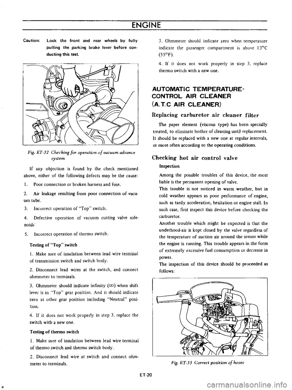
Fig
ET
32
Checking
for
operation
of
vacuum
advance
system
If
any
objection
is
found
by
the
check
mentioned
above
either
of
the
following
defects
may
be
the
cause
Poor
connection
or
broken
harness
and
fuse
2
Air
leakage
resulting
from
poor
connection
of
vacu
um
tube
3
Incorrect
operation
of
Top
switch
4
Defective
operation
of
vacuum
cutting
valve
sole
naid
5
Incorrect
operation
of
thermo
switch
Testing
of
Top
switch
1
Make
sure
of
insulation
between
lead
wire
terminal
of
transmission
switch
and
switch
body
2
Disconnect
lead
wires
at
the
switch
and
connect
ohmmeter
to
tenninals
3
Ohmmeter
should
indicate
infmity
co
when
shift
lever
is
in
Top
gear
position
And
it
should
indicate
zero
at
other
gear
position
including
Neutral
posi
tion
4
If
it
does
not
work
properly
in
step
3
replace
the
switch
with
a
new
one
Testing
of
thermo
switch
I
MaJ
e
sure
of
insulation
between
lead
wire
terminal
of
thermo
switch
and
thetmo
switch
body
2
Disconnect
lead
wire
at
switch
and
connect
ohm
meter
to
terminals
Ohmmeter
should
indicate
zero
when
temperature
indicate
the
passenger
compartment
is
above
l30C
550F
4
If
it
does
not
work
properly
in
step
3
replace
thermo
switch
with
a
new
one
AUTOMATIC
TEMPERATURE
CONTROL
AIR
CLEANER
A
T
C
AIR
CLEANER
Replacing
carburetor
air
cleaner
filter
The
paper
element
viscous
type
has
been
specially
treated
to
eliminate
bother
of
cleaning
until
replacement
It
should
be
replaced
with
a
new
one
at
regular
intervals
or
more
often
according
to
the
operating
conditions
Checking
hot
air
control
valve
Inspection
Among
the
possible
troubles
of
this
device
the
most
liable
is
the
permanent
opening
of
valve
This
trouble
is
not
noticed
in
warm
weather
but
in
cold
weather
appears
as
poor
performance
of
engine
such
as
tardy
acceleration
hesitation
or
engine
stall
In
such
case
first
inspect
this
device
before
checking
the
carburetor
Another
trouble
which
might
be
expected
is
that
the
underhood
air
is
kept
closed
by
the
valve
regardless
of
the
temperature
of
suction
air
around
the
sensor
while
the
engine
is
running
This
ttOuble
appears
in
the
form
of
extremely
excessive
fuel
consumption
or
decrease
in
power
The
inspection
of
this
device
should
be
proceeded
as
follows
Fig
ET
33
Correct
position
of
hoses
ET
20
Page 392 of 513
FUEl
SYSTEM
AUTOMATIC
TEMPERATURE
CONTROL
AIR
CLEANER
A
T
C
AIR
CLEANER
CONTENTS
DESCRIPTION
Air
cleaner
element
Automatic
temperature
control
air
cleaner
EF
1
EF
1
EF
2
TEMPERATURE
SENSOR
Removal
and
installation
EF
4
EF
4
DESCRIPTION
Air
cleaner
element
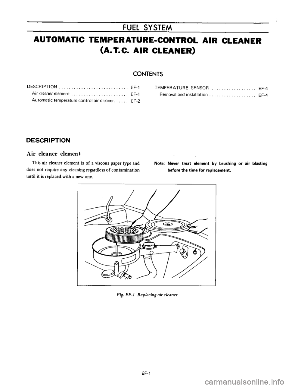
This
air
cleaner
element
is
of
a
viscous
paper
type
and
does
not
require
any
cleaning
regardless
of
contamination
until
it
is
replaced
with
a
new
one
Note
Never
treat
element
by
brushing
or
air
blasting
before
the
time
for
replacement
Fig
EF
l
Replacing
air
cleaner
EF
1
Page 396 of 513

FUEl
SYSTEM
FUEL
STRAINER
DESCRIPTION
The
fuel
strainer
is
of
a
cartridge
type
It
uses
paper
element
as
strainer
element
which
can
be
checked
for
condition
from
outside
This
strainer
cannot
be
cleaned
Replace
the
strainer
at
the
specified
service
interval
or
if
it
becomes
clogged
or
restricted
REMOVAL
Disconnect
inlet
and
outlet
fuel
lines
from
fuel
strainer
and
remove
fuel
strainer
Note
Before
disconnecting
fuel
lines
use
a
container
to
receive
the
remaining
fuel
in
lines
r
@
I
I
Il
QY
I
I
I
elementl
3
Cover
@
EF005
Fig
EF
10
Sectional
view
of
caTtridge
type
fuel
stTaineT
FUEL
PUMP
CONTENTS
DESCRIPTION
FUEL
PUMP
TESTING
Static
pressure
test
Capacity
test
EF
5
EF
6
EF
6
EF
6
DESCRIPTION
The
fuel
pump
transfers
gasoline
from
the
tank
to
the
carburetor
in
sufficient
quantity
to
meet
engine
require
ments
at
any
speed
or
load
The
fuel
pump
is
of
the
diaphragm
type
REMOVAL
AND
DISASSEMBLY
INSPECTION
ASSEMBLY
EF
7
EF
B
EF
B
The
fuel
pump
consists
of
a
body
rocker
arm
and
link
assembly
fuel
diaphragm
fuel
diaphragm
spring
seal
inlet
and
outlet
valves
The
fuel
diaphragm
consists
of
specially
treated
rubber
which
is
not
affected
by
gasoline
held
together
with
two
metal
discs
and
a
pull
rod
EF
5
Page 399 of 513
ENGINE
INSPECTION
Check
the
upper
and
lower
bodies
for
cracks
2
Check
the
valve
assembly
for
wear
of
the
valve
and
valve
spring
Blow
the
valve
assembly
by
breath
to
examine
its
function
3
Check
the
diaphragm
for
small
holes
cracks
and
wear
4
Check
the
rocker
arm
for
wear
at
the
portion
in
contact
with
the
camshaft
5
Check
the
rocker
arm
pin
for
wear
since
a
worn
pin
may
cause
oil
leakage
6
Check
all
other
components
for
any
abnormalities
and
replace
with
new
parts
as
required
ASSEMBLY
Assembly
is
done
in
reverse
order
of
disassembly
For
reassembly
and
reinstallation
the
following
matters
should
be
noted
Use
new
gasket
2
Lubricate
the
rocker
arm
link
rocker
arm
pin
and
lever
pin
before
installation
3
To
test
the
function
position
the
fuel
pump
assem
bly
about
I
meter
3
3
ft
above
fuel
level
with
a
pipe
connecting
the
fuel
pump
and
the
fuel
strainer
and
operate
the
rocker
afm
by
hand
If
fuel
is
drawn
up
soon
after
the
rocker
arm
is
released
the
function
of
the
pump
is
satisfactory
CARBURETOR
CONTENTS
DESCRIPTION
STRUCTURE
AND
OPERATION
EF
8
EF
9
EF
10
EF
11
EF
12
EF
12
EF
12
EF
14
EF
14
EF
15
EF
15
EF
16
EF
16
Primary
system
Secondary
system
Anti
dieseling
solenoid
valve
Float
system
Electric
automatic
choke
ADJUSTMENT
Idling
adjustment
Fuel
level
adjustment
Fast
idle
adjustment
Vacuum
break
adjustment
Choke
un
loader
adjustment
DESCRIPTION
The
carburetors
are
of
a
downdraft
type
which
is
designed
and
built
to
increase
power
and
fuel
economy
as
Bi
metal
setting
Adjustment
of
interlock
opening
of
primary
and
secondary
throttle
valves
Dash
pot
adjustment
MAJOR
SERVICE
OPERATIONS
Removal
Disassembly
Cleaning
and
inspection
Assembly
and
installation
JETS
SERVICE
DATA
AND
SPECIFICATIONS
TROUBLE
DIAGNOSES
AND
CORRECTIONS
EF
17
EF
18
EF
18
EF
19
EF
19
EF
19
EF
21
EF
22
EF
22
EF
22
EF
22
well
as
to
reduce
the
emission
of
exhaust
gases
These
carburetors
present
several
distinct
features
of
importance
to
the
car
owners
A
summary
of
features
is
as
follows
EF
8
Page 400 of 513
FUEl
SYSTEM
Secondary
throttle
valve
is
operated
by
throttle
lever
The
high
power
and
good
acceleration
are
gained
with
combination
of
the
auxiliary
valve
2
Accelerating
pump
gives
excellent
acceleration
3
The
power
valve
mechanism
is
of
a
vacuum
actuated
boost
type
and
improves
high
speed
driving
4
The
throttle
opener
control
system
Refer
to
Section
ET
incorporates
a
servo
diaphragm
The
servo
dia
phragm
helps
open
the
throttle
valve
at
a
decreasing
speed
so
as
to
reduce
the
emission
of
hydrocarbons
to
a
minimum
5
An
anti
dieseling
solenoid
is
used
as
a
means
of
preventing
dieseling
When
the
ignition
key
is
turned
off
the
fuel
passage
involved
in
the
slow
system
is
closed
and
the
fuel
supply
is
shut
down
completely
6
In
the
choke
mechanism
an
electric
automatic
choke
is
used
to
automatically
control
the
choke
valve
operation
during
the
warm
up
of
the
engine
7
The
carburetor
for
automatic
transmission
is
equipped
with
so
called
dash
pot
that
is
it
makes
smooth
decelerating
without
engine
stall
at
any
operating
condi
tion
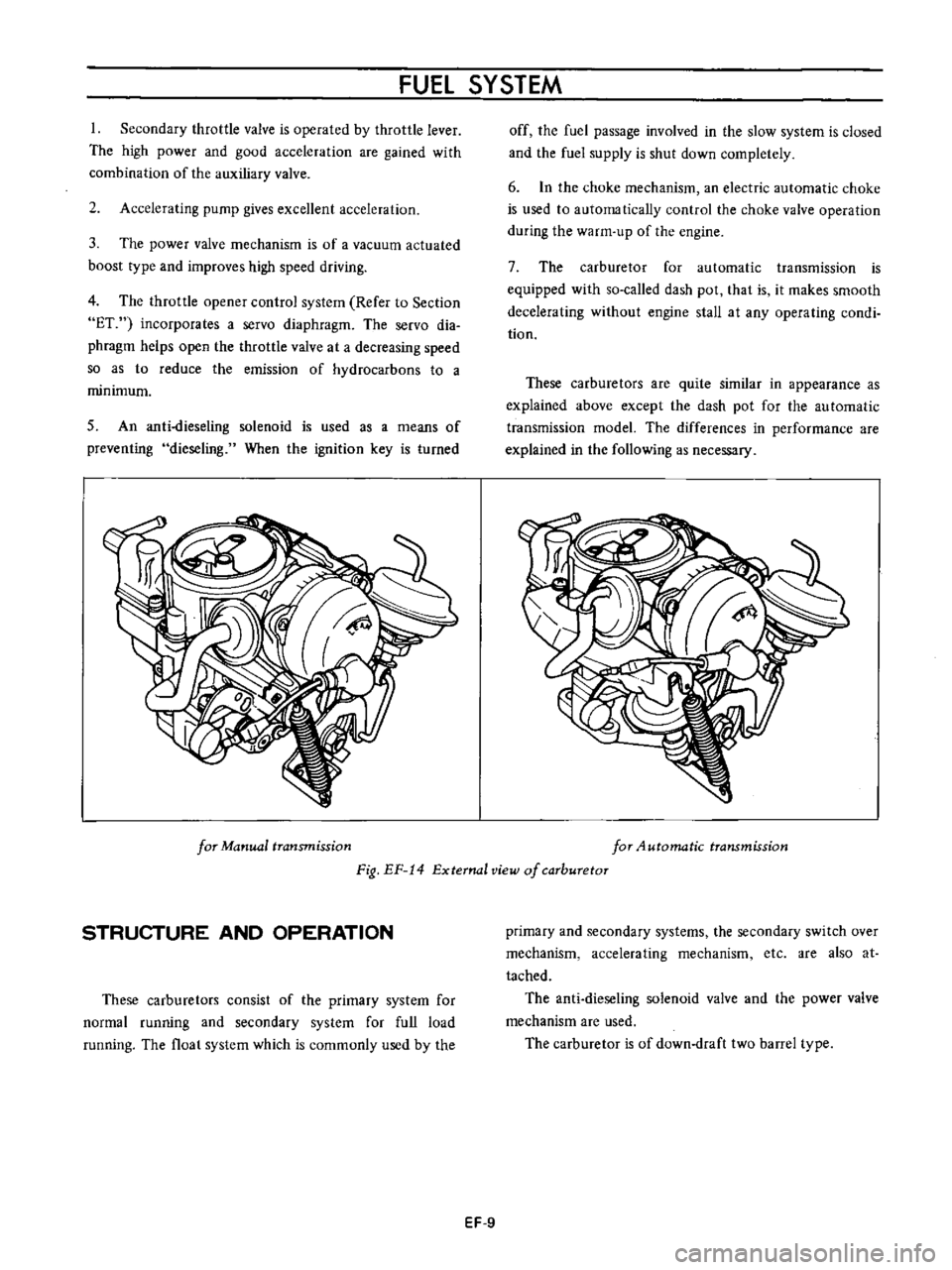
These
carburetors
are
quite
similar
in
appearance
as
explained
above
except
the
dash
pot
for
the
au
tomatic
transmission
model
The
differences
in
performance
are
explained
in
the
following
as
necessary
for
Manual
transmission
for
4utomatic
transmission
Fig
EF
14
External
view
of
carburetor
STRUCTURE
AND
OPERATION
These
carburetors
consist
of
the
primary
system
for
normal
running
and
secondary
system
for
full
load
running
The
float
system
which
is
commonly
used
by
the
primary
and
secondary
systems
the
secondary
switch
over
mechanism
accelerating
mechanism
etc
are
also
at
tached
The
anti
dieseling
solenoid
valve
and
the
power
valve
mechanism
are
used
The
carburetor
is
of
down
draft
two
barrel
type
EF
9
Page 402 of 513
FUEl
SYSTEM
Idling
and
slow
system
Passing
through
the
main
jet
the
fuel
passage
is
separated
from
main
line
fuel
flows
through
the
slow
jet
primary
slow
air
bleed
is
ejected
from
the
by
pass
hole
and
idle
nozzle
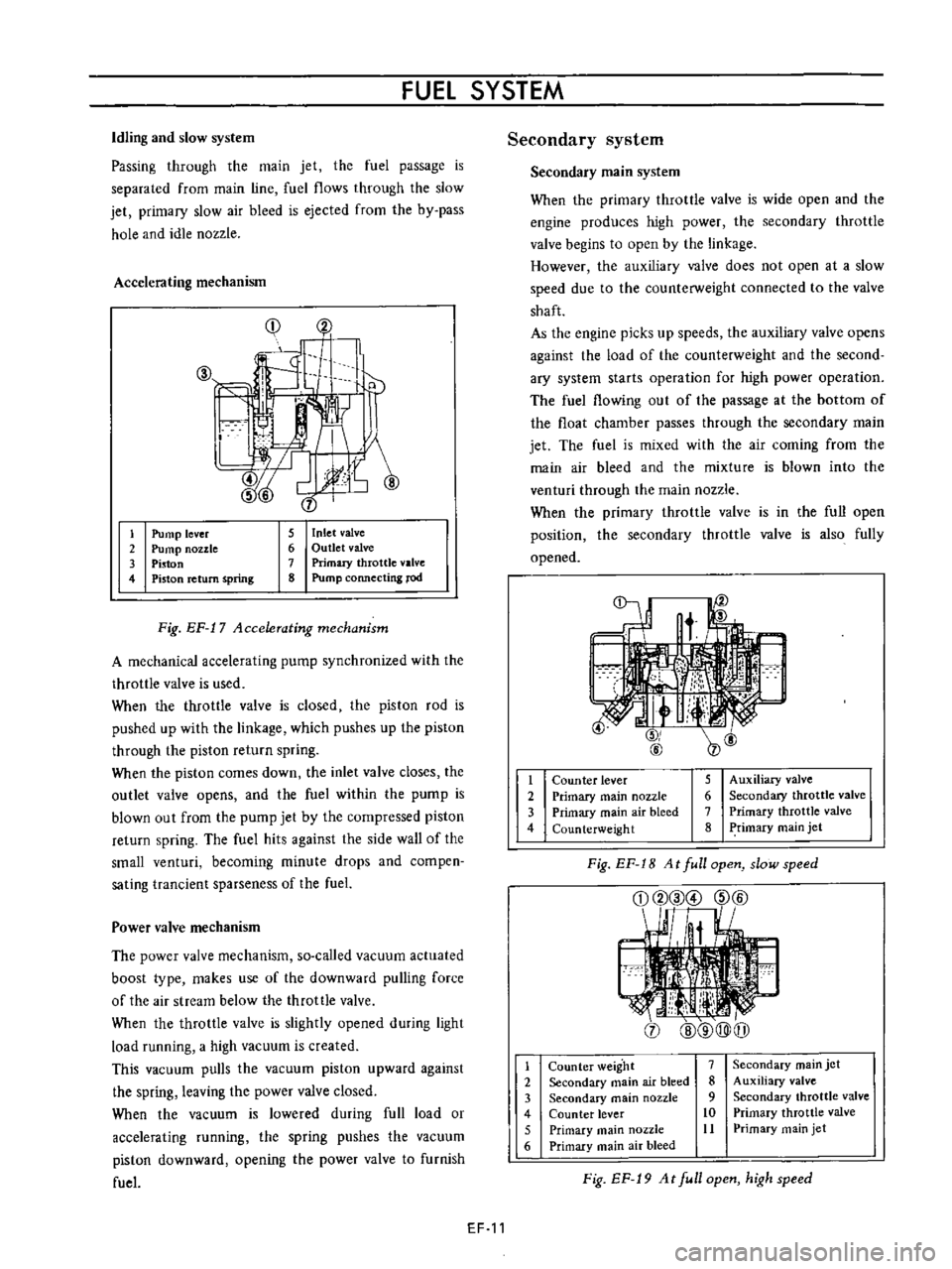
Accelerating
mechanism
Cj
f
li
Ip
j
1
2
3
4
5
Inlet
valve
6
Outlet
valve
7
Primary
throttle
valve
8
Pump
connecting
rod
Pump
lever
Pump
nozzle
Piston
Piston
return
spring
Fig
EF
17
Accelerating
mechanism
A
mechanical
accelerating
pump
synchronized
with
the
throttle
valve
is
used
When
the
throttle
valve
is
closed
the
piston
rod
is
pushed
up
with
the
linkage
which
pushes
up
the
piston
through
the
piston
return
spring
When
the
piston
comes
down
the
inlet
valve
closes
the
outlet
valve
opens
and
the
fuel
within
the
pump
is
blown
out
from
the
pump
jet
by
the
compressed
piston
return
spring
The
fuel
hits
against
the
side
wall
of
the
small
venturi
becoming
minute
drops
and
compen
sating
trancient
sparseness
of
the
fuel
Power
valve
mechanism
The
power
valve
mechanism
so
called
vacuum
actuated
boost
type
makes
use
of
the
downward
pulling
force
of
the
air
stream
below
the
throttle
valve
When
the
throttle
valve
is
slightly
opened
during
light
load
running
a
high
vacuum
is
created
This
vacuum
pulls
the
vacuum
piston
upward
against
the
spring
leaving
the
power
valve
closed
When
the
vacuum
is
lowered
during
full
load
or
accelerating
running
the
spring
pushes
the
vacuum
piston
downward
opening
the
power
valve
to
furnish
fuel
EF
11
Secondary
system
Secondary
main
system
When
the
primary
throttle
valve
is
wide
open
and
the
engine
produces
high
power
the
secondary
throttle
valve
begins
to
open
by
the
linkage
However
the
auxiliary
Y
J
lve
does
not
open
at
a
slow
speed
due
to
the
counterweight
connected
to
the
valve
shaft
As
the
engine
picks
up
speeds
the
auxiliary
valve
opens
against
the
load
of
the
counterweight
and
the
second
ary
system
starts
operation
for
high
power
operation
The
fuel
flowing
out
of
the
passage
at
the
bottom
of
the
float
chamber
passes
through
the
secondary
main
jet
The
fuel
is
mixed
with
the
air
coming
from
the
main
air
bleed
and
the
mixture
is
blown
into
the
venturi
through
the
main
nozzle
When
the
primary
throttle
valve
is
in
the
full
open
position
the
secondary
throttle
valve
is
also
fully
opened
t
2
3
4
5
Auxiliary
valve
6
Secondary
throttle
valve
7
Primary
throttle
valve
8
Primary
main
jet
Counter
lever
Primary
main
nozzle
Primary
main
air
bleed
Counterweight
Fig
EF
1B
At
full
open
slow
speed
j
1
2
3
4
5
6
Counter
weight
7
Secondary
main
air
bleed
8
Secondary
main
nozzle
9
Counter
lever
10
Primary
main
nozzle
11
Primary
main
air
bleed
Secondary
main
jet
Auxiliary
valve
Secondary
throttle
valve
Primary
throttle
valve
Primary
main
jet
Fig
EF
19
At
full
open
high
speed
Page 412 of 513
FUEL
SYSTEM
5
Check
venturi
clusters
for
loose
or
worn
parts
If
damage
or
looseness
exists
replace
cluster
assembly
6
Check
the
linkage
for
operating
condition
7
Inspect
the
operation
of
accelerating
pump
Pour
gasoline
into
the
float
chamber
and
operate
the
throttle
lever
Check
condition
of
gasoline
injection
from
the
accelerating
nozzle
Assembly
and
instalIetion
Assemble
and
install
the
carburetor
in
reverse
sequence
of
disassembly
and
removal
Replace
the
gaskets
if
necessary
When
disassembling
and
reassembling
the
interlock
link
and
related
components
be
careful
not
to
bend
or
deform
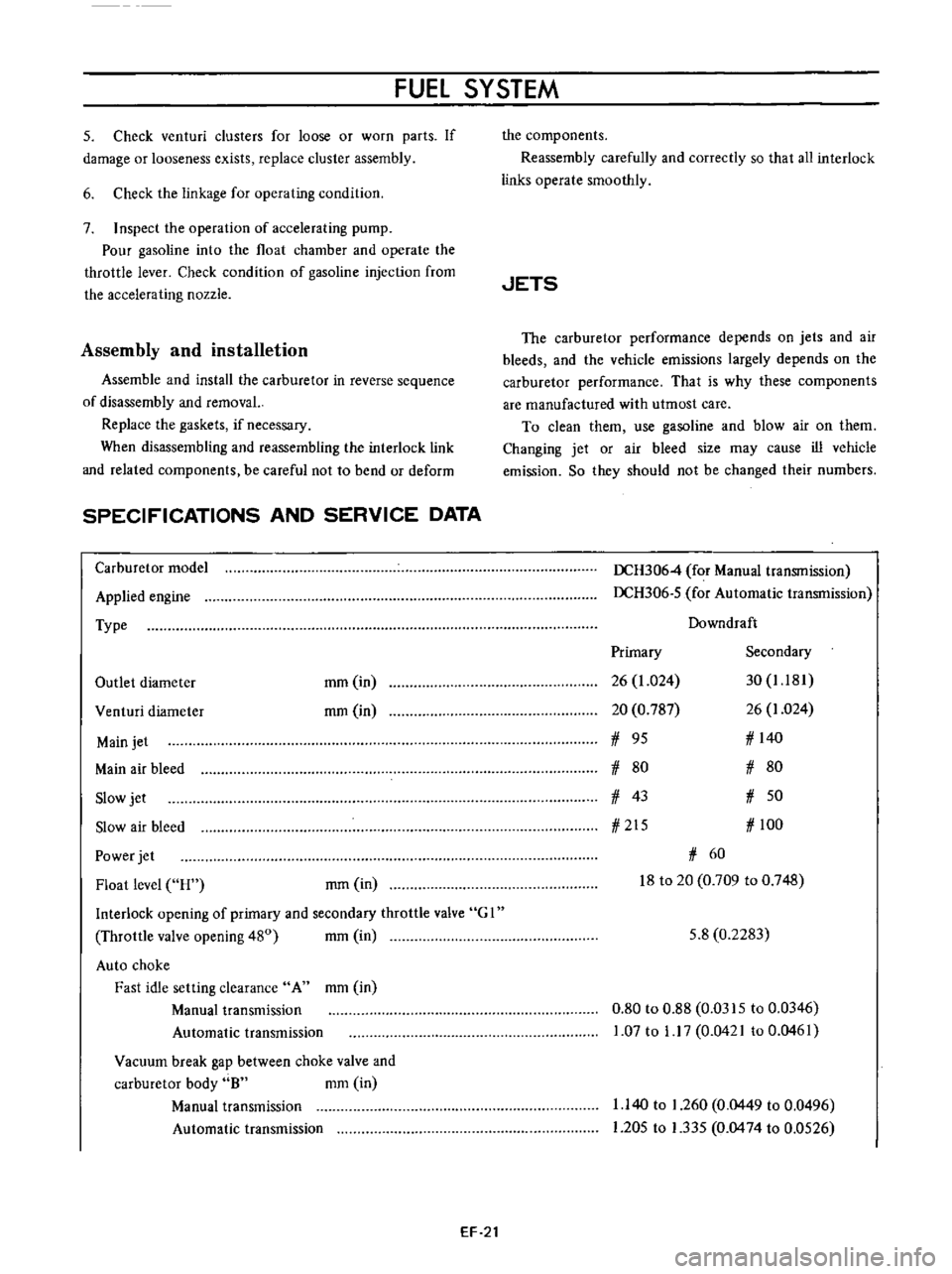
SPECIFICATIONS
AND
SERVICE
DATA
Carburetor
model
Applied
engine
Type
Outlet
diameter
mm
in
rom
in
Venturi
diameter
Main
jet
Main
air
bleed
Slow
jet
Slow
air
bleed
Power
jet
Float
level
H
rom
in
Interlock
opening
of
primary
and
secondary
throttle
valve
G
I
Throttle
valve
opening
480
mm
in
Auto
choke
Fast
idle
setting
clearance
A
mm
in
Manual
transmission
Automatic
transmission
Vacuum
break
gap
between
choke
valve
and
carburetor
body
8
mm
in
Manual
transmission
Automatic
transmission
EF
21
the
components
Reassembly
carefully
and
correctly
so
that
all
interlock
links
operate
smoothly
JETS
The
carburetor
performance
depends
on
jets
and
air
bleeds
and
the
vehicle
emissions
largely
depends
on
the
carburetor
performance
That
is
why
these
components
are
manufactured
with
utmost
care
To
clean
them
use
gasoline
and
blow
air
on
them
Changing
jet
or
air
bleed
size
may
cause
ill
vehicle
emission
So
they
should
not
be
changed
their
numbers
DCH3064
for
Manual
transmission
DCH306
5
for
Automatic
transmission
Downdraft
Primary
Secondary
26
1
024
30
1
181
20
0
787
26
1
024
1
95
1
140
1
80
1
80
1
43
1
50
1
215
1
100
1
60
18
to
20
0
709
to
0
748
5
8
0
2283
0
80
to
0
88
0
0315
to
0
0346
1
07
to
1
17
0
0421
to
0
0461
1
140
to
1
260
0
0449
to
0
0496
1
205
to
1
335
0
0474
to
0
0526