1973 DATSUN B110 height
[x] Cancel search: heightPage 377 of 513
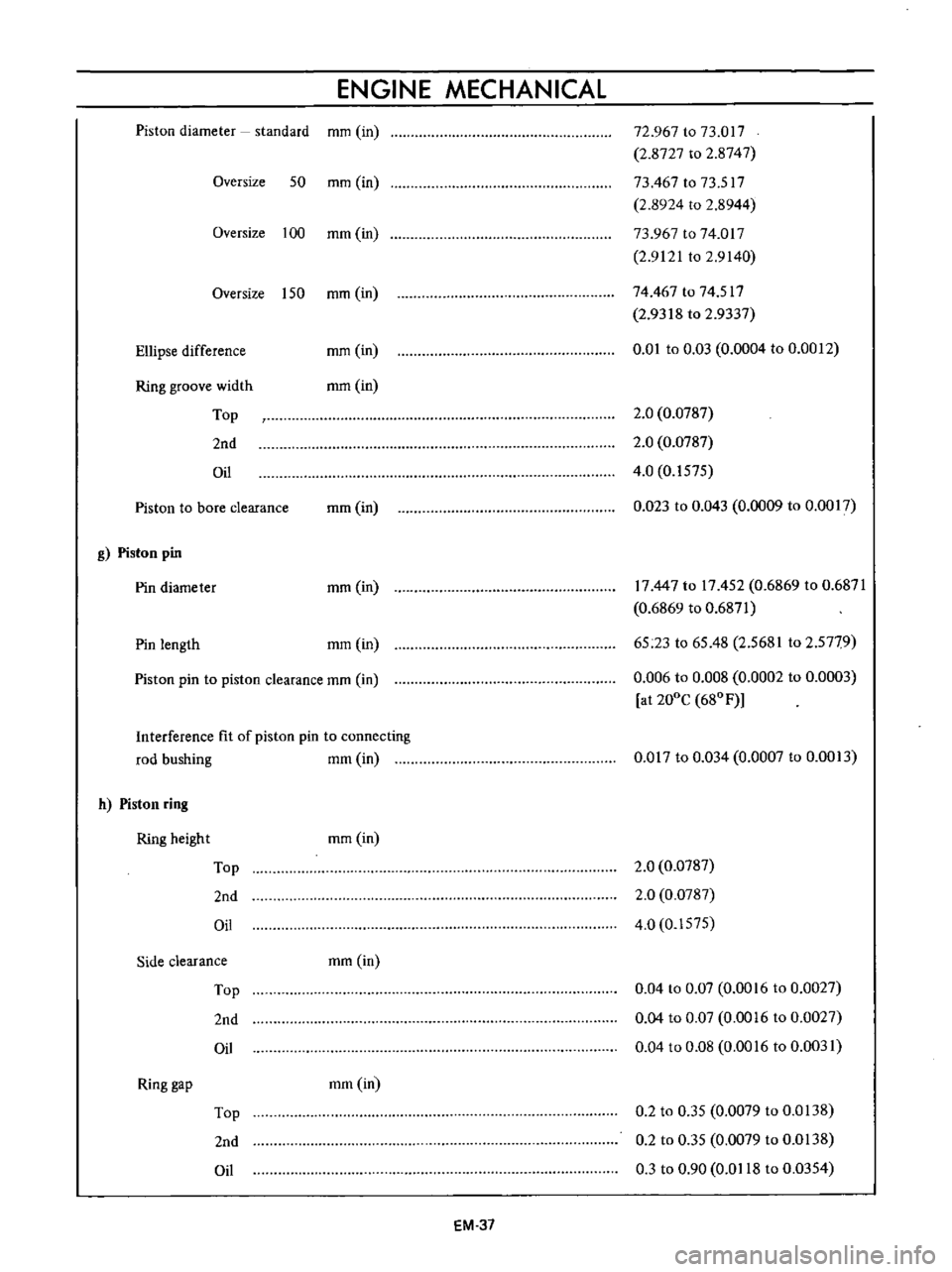
ENGINE
MECHANICAL
Piston
diameter
standard
mm
in
Oversize
50
mm
in
Oversize
100
mm
in
Oversize
150
mm
in
Ellipse
difference
mm
in
Ring
groove
width
Top
2nd
Oil
mm
in
Piston
to
bore
clearance
mm
in
g
Piston
pin
Pin
diameter
mm
in
Pin
length
mm
in
Piston
pin
to
piston
clearance
mm
in
Interference
fit
of
piston
pin
to
connecting
rod
bushing
mm
in
h
Piston
ring
Ring
height
Top
2nd
Oil
mm
in
Side
clearance
mm
in
Top
2nd
Oil
Ring
gap
mm
in
Top
2nd
Oil
EM
37
72
967
to
73
017
2
8727
to
2
8747
73
467
to
73
517
2
8924
to
2
8944
73
967
to
74
017
2
9121
to
2
9140
74
467
to
74
517
2
9318
to
2
9337
0
01
to
0
03
0
0004
to
0
0012
2
0
0
0787
2
0
0
0787
4
0
0
1575
0
023
to
0
043
0
0009
to
0
0017
17
447
to
17
452
0
6869
to
0
6871
0
6869
to
0
6871
65
23
to
65
48
2
5681
to
2
5779
0
006
to
0
008
0
0002
to
0
0003
at
200e
680
F
0
017
to
0
034
0
0007
to
0
0013
2
0
0
0787
2
0
0
0787
4
0
0
1575
0
04
to
0
07
0
0016
to
0
0027
0
04
to
0
07
0
0016
to
0
0027
0
04
to
0
08
0
0016
to
0
0031
0
2
to
0
35
0
0079
to
0
0138
0
2
to
0
35
0
0079
to
0
0138
0
3
to
0
90
0
0118
to
0
0354
Page 390 of 513
ENGINE
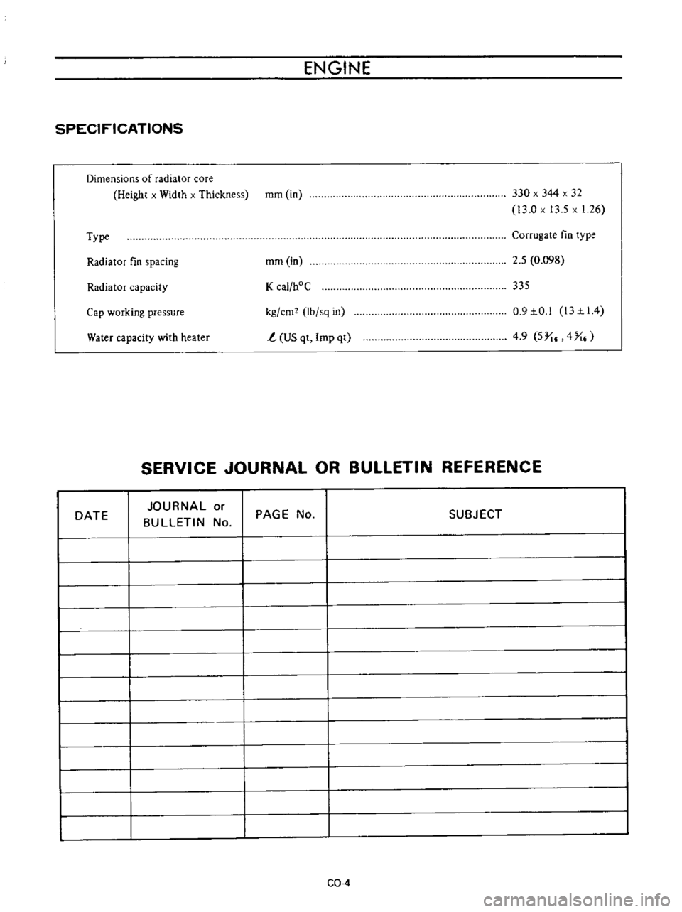
SPECIFICATIONS
Dimensions
of
radiator
core
Height
x
Width
x
Thickness
mm
in
330
x
344
x
32
13
0
x
13
5
x
1
26
Type
Corrugate
fin
type
Radiator
fin
spacing
mm
in
2
5
0
098
Radiator
capacity
K
cal
hoC
335
Water
capacity
with
heater
kg
em
lb
sq
in
t
US
qt
Imp
qt
0
9IO
l
13II4
4
9
5
I
4
X
Cap
working
pressure
SERVICE
JOURNAL
OR
BULLETIN
REFERENCE
DATE
JOURNAL
or
BULLETIN
No
PAGE
No
SUBJECT
CQ
4
Page 417 of 513
ENGINE
ffi68
mmAq
14
5
mAq
3
way
connector
Cock
II
M
nam
e
Flow
guide
valve
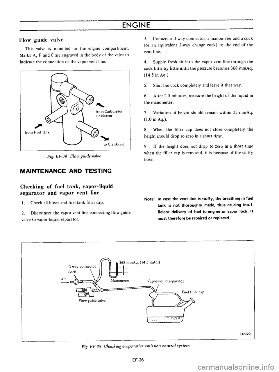
This
valve
is
mounted
in
the
engine
compartment
f
tHks
A
F
and
C
are
engraved
in
the
body
of
the
valve
to
indicate
the
connection
of
the
vapor
vent
line
l
l
1
from
Fuel
tank
to
Crankcase
Fig
EF
3B
Flow
guide
valve
MAINTENANCE
AND
TESTING
Checking
of
fuel
tank
vapor
liquid
separator
and
vapor
vent
line
Check
all
hoses
and
fuel
tank
filler
cap
2
Disconnect
the
vapor
vent
line
connecting
flow
guide
valve
to
vapor
liquid
separator
Flow
guide
valve
3
Connect
a
J
way
connector
a
manometer
and
a
l
ul
k
or
an
equivalent
3
wav
change
cock
to
the
end
of
the
vent
line
4
Supply
fresh
air
into
the
vapor
vent
line
through
the
cock
little
by
little
until
the
pressure
becomes
368
romAq
14
5
in
Aq
5
Shut
the
cock
completely
and
leave
it
that
way
6
After
2
5
minutes
measure
the
height
uf
the
liquid
in
the
manometer
7
Variation
of
height
should
remain
within
25
mmAq
1
0
in
Aq
8
When
the
filler
cap
does
not
close
completely
the
height
should
drop
to
zero
in
a
short
time
9
I
f
the
height
docs
not
drop
to
zero
in
a
short
time
when
the
filler
cap
is
removed
it
is
because
of
the
stuffy
hose
Note
In
case
the
vent
line
is
stuffy
the
breathing
in
fuel
tank
is
not
thoroughly
made
thus
causing
insuf
ficient
delivery
of
fuel
to
engine
or
vapor
lock
It
must
therefore
be
repaired
or
replaced
1
m
eparator
1
Fuel
filler
cap
Y
XI
EC029
Fig
EF
39
Checking
evaporative
emission
control
system
EF
26
Page 426 of 513
ENGINE
CLEANING
AND
INSPECTION
Clean
all
disassembled
parts
Be
careful
not
to
use
grease
dissolving
solvent
for
cleaning
of
the
over
running
clutch
armature
assembly
magnetic
switch
assembly
and
field
coils
since
solvent
dissolves
grease
packed
in
the
clutch
mechanism
and
damages
the
coils
or
insulators
Check
them
for
damage
or
excessive
wear
Replace
them
as
required
Terminal
Check
the
terminal
for
damage
and
wear
and
replace
if
necessary
Field
coil
Check
the
field
coil
for
insulation
If
the
coil
insulator
is
damaged
or
worn
replace
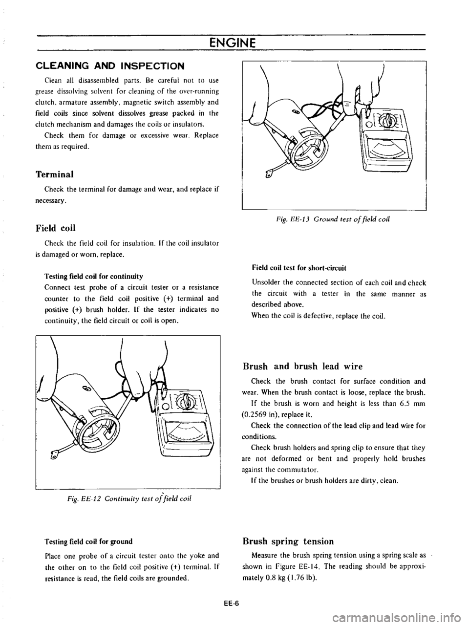
Testing
field
coil
for
continuity
Connect
test
probe
of
a
circuit
tester
or
a
resistance
counter
to
the
field
coil
positive
terminal
and
positive
brush
holder
If
the
tester
indicates
no
continuity
the
field
circuit
or
coil
is
open
O
Fig
EE
12
Cotltinuity
test
of
field
coil
Testing
field
coil
for
ground
Place
one
probe
of
a
circuit
tester
onto
the
yoke
and
the
othef
on
to
the
field
coil
positive
tenninal
If
resistance
is
read
the
field
coils
are
grounded
ol
I
Fig
EE
13
CTound
test
of
field
coil
Field
coil
test
for
short
ircuit
Un
solder
the
connected
section
of
each
coil
and
check
the
circuit
with
a
tester
in
the
same
manner
as
described
above
When
the
coil
is
defective
replace
the
coil
Brush
and
brush
lead
wire
Check
the
brush
contact
for
surface
condition
and
wear
When
the
brush
contact
is
loose
replace
the
brush
If
the
brush
is
worn
and
height
is
less
than
6
5
rom
0
2569
in
replace
it
Check
the
connection
of
the
lead
clip
and
lead
wire
for
conditions
Check
brush
holders
and
spring
clip
to
ensure
that
they
are
not
deformed
or
bent
and
properly
hold
brushes
against
the
commutator
If
the
brushes
Of
brush
holders
are
dirty
clean
Brush
spring
tension
Measure
the
brush
spring
tension
using
a
spring
scale
as
shown
in
Figure
EE
14
The
reading
should
be
approxi
mately
0
8
kg
I
76
Ib
EE
6
Page 431 of 513
ENGINE
ElECTRICAL
SYSTEM
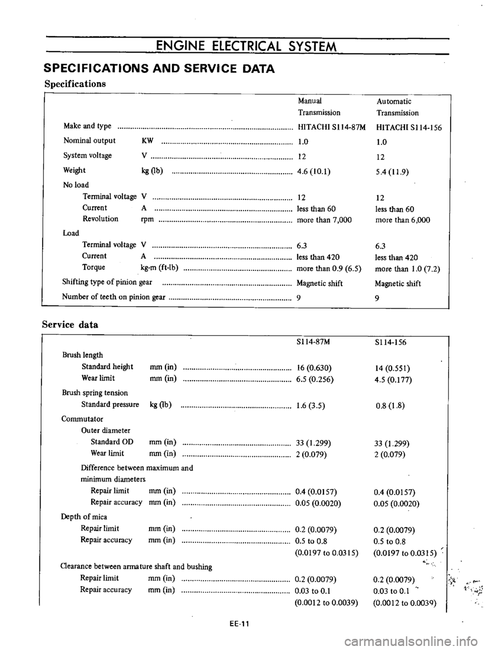
SPECIFICATIONS
AND
SERVICE
DATA
Specifications
Manual
Automatic
Transmission
Transmission
Make
and
type
HITACHI
SI14
87M
HITACHI
S114
156
Nominal
output
KW
1
0
1
0
System
voltage
V
12
12
Weight
kg
Qb
4
6
10
1
54
11
9
No
load
Terminal
voltage
V
12
12
Current
A
less
than
60
less
than
60
Revolution
rpm
more
than
7
000
more
than
6
000
Load
Terminal
voltage
V
6
3
6
3
Current
A
less
than
420
less
than
420
Torque
kg
m
ft
Ib
more
than
0
9
6
5
more
than
1
0
7
2
Shifting
type
of
pinion
gear
Magnetic
shift
Magnetic
shift
Number
of
teeth
on
pinion
gear
9
9
Service
data
S114
87M
S114
156
Brush
length
Standard
height
mm
in
16
0
630
14
0
551
Wear
limit
mm
in
6
5
0
256
4
5
0
177
Brush
spring
tension
Standard
pressure
kg
Qb
1
6
3
5
0
8
1
8
Commutator
Outer
diameter
Standard
OD
mm
in
33
1
299
33
I
299
Wear
limit
mm
in
2
0
079
2
0
079
Difference
between
maximum
and
minimum
diameters
Repair
limit
mm
in
0
4
0
0157
0
4
0
0157
Repair
accuracy
mm
in
0
05
0
0020
0
05
0
0020
Depth
of
mica
Repair
limit
mm
in
0
2
0
0079
0
2
0
0079
Repair
accuracy
mm
in
0
5
to
0
8
0
5
to
0
8
0
0197
to
0
0315
0
0197
to
0
0315
Clearance
between
arma
ture
shaft
and
bushing
mm
in
Repair
limit
0
2
0
0079
0
2
0
0079
Vi
Repair
accuracy
mm
in
0
03
to
0
1
0
03
to
0
1
1
r
0
0012
to
0
0039
0
0012
to
0
003Q
EE
11
Page 473 of 513
CLUTCH
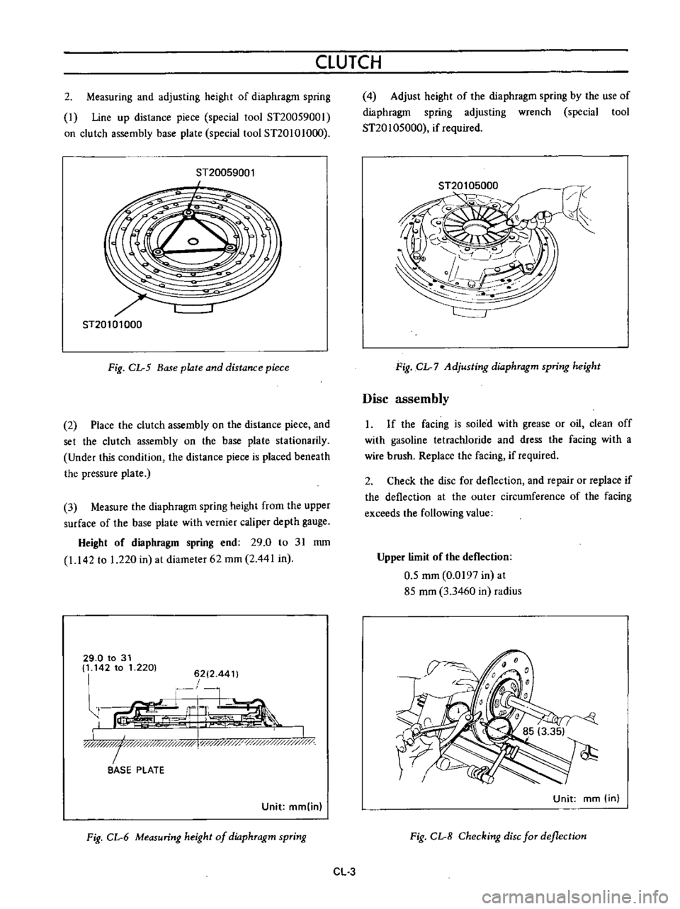
2
Measuring
and
adjusting
height
of
diaphragm
spring
I
Line
up
distance
piece
special
tool
ST20059001
on
clutch
assembly
base
plate
special
tool
ST20101O
0
ST20059001
I
ST20101000
Fig
CL
5
Base
plate
and
distance
piece
2
Place
the
clutch
assembly
on
the
distance
piece
and
set
the
clutch
assembly
on
the
base
plate
stationarily
Under
this
condition
the
distance
piece
is
placed
beneath
the
pressure
plate
3
Measure
the
diaphragm
spring
height
from
the
upper
surface
of
the
base
plate
with
vernier
caliper
depth
gauge
Height
of
diaphragm
spring
end
29
0
to
31
mm
1
142
to
1
220
in
at
diameter
62
mm
2
441
in
29
0
to
31
It
142
to
1
2201
6212
44
t
r
1
G
L
ir
I
LJIlW
I
y
y
x
l
i
0
BASE
PLATE
Unit
mm
in
Fig
CL
6
Measuring
height
of
dio
phTagm
spTing
4
Adjust
height
of
the
diaphragm
spring
by
the
use
of
diaphragm
spring
adjusting
wrench
special
tool
ST20
1
05000
if
required
Fig
CL
7
Adjusting
dio
phTagm
spring
height
Disc
assembly
If
the
facing
is
soiled
with
grease
or
oil
clean
off
with
gasoline
tetracWoride
and
dress
the
facing
with
a
wire
brush
Replace
the
facing
if
required
2
Check
the
disc
for
deflection
and
repair
or
replace
if
the
deflection
at
the
outer
circumference
of
the
facing
exceeds
the
following
value
Upper
limit
of
the
deflection
0
5
mm
0
0197
in
at
85
mm
3
3460
in
radius
Unit
mm
in
Fig
CL
8
Checking
disc
fOT
deflection
CL
3
Page 474 of 513
CHASSIS
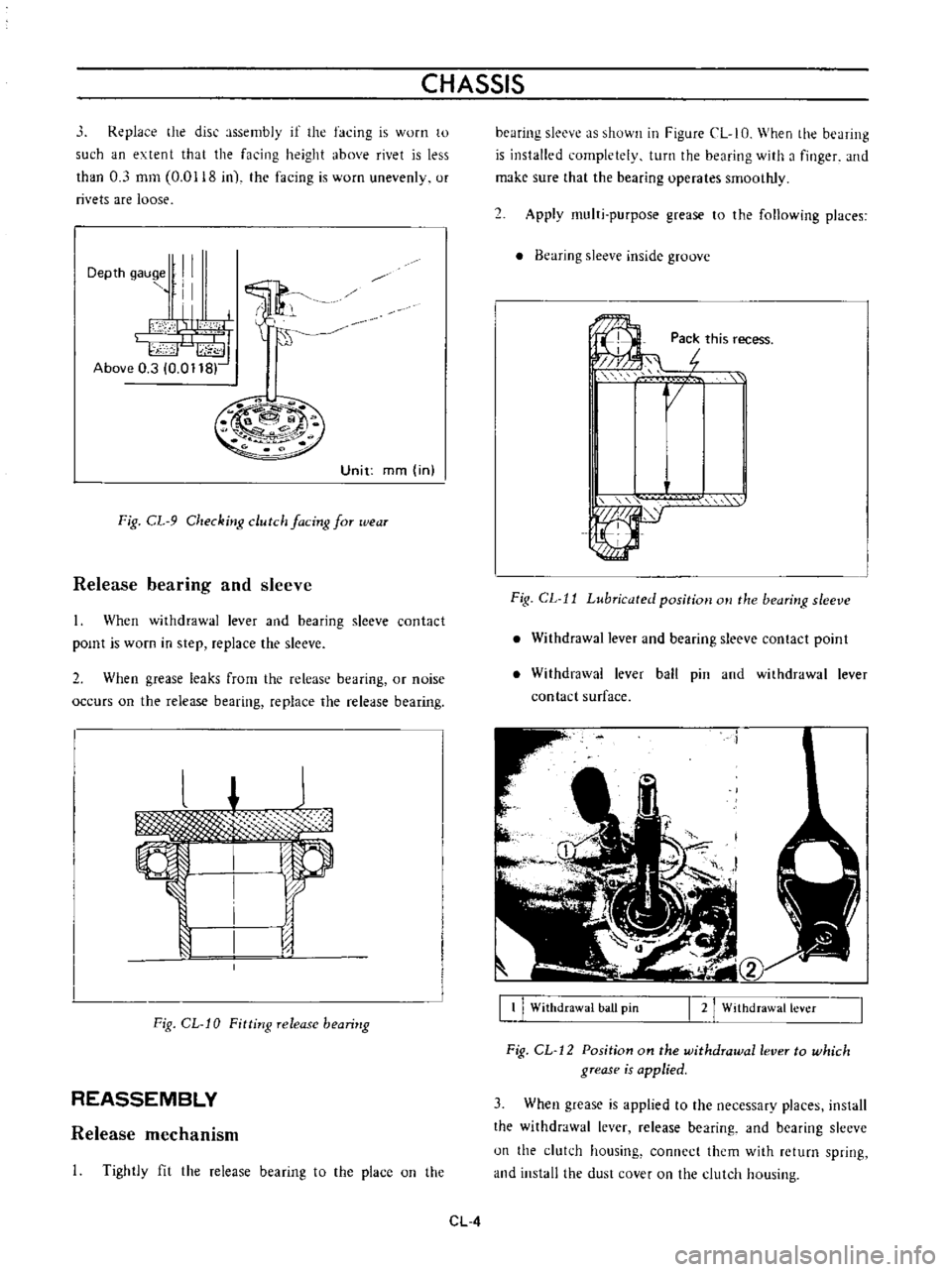
Replace
the
disc
assembly
if
the
facing
is
worn
to
such
an
extent
that
the
facing
height
above
rivet
is
less
than
0
3
mm
0
0118
in
the
facing
is
worn
unevenly
or
rivets
are
loose
Depth
9au@e
II
i
I
I
il
S
I
I
F
d
I
id
Above
0
3
10
0118
Unit
mm
in
Fig
CL
9
Checking
clutch
facing
for
wear
Release
bearing
and
sleeve
When
withdrawal
lever
and
bearing
sleeve
contact
pomt
is
worn
in
step
replace
the
sleeve
2
When
grease
leaks
from
the
release
bearing
or
noise
occurs
on
the
release
bearing
replace
the
release
bearing
Fig
CL
J
0
Fittitlg
release
bearir
g
REASSEMBLY
Release
mechanism
Tightly
fit
the
release
bearing
to
the
placc
on
the
bearing
sleeve
as
shown
in
Figure
CL
10
When
the
hearing
is
installed
completely
turn
the
bearing
with
a
finger
and
make
sure
that
the
bearing
operates
smoothly
2
Apply
multi
purpose
grease
to
the
following
places
Bearing
sleeve
inside
groove
l
Pack
this
recess
I
1
II
J
Fig
CL
11
Lubricated
position
m
the
bearing
sleeve
Withdrawal
lever
and
bearing
sleeve
contact
point
Withdrawal
lever
ball
pin
and
withdrawal
lever
contact
surface
I
I
1
Withdrawal
ball
pin
I
2
Withdrawal
lever
Fig
CL
12
Position
on
the
withdrawal
lever
to
which
grease
is
applied
3
When
grease
is
applied
to
the
necessary
places
install
the
withdrawal
lever
release
bearing
and
bearing
sleeve
un
the
clukh
housing
connect
them
with
return
spring
and
install
the
dust
cover
on
the
clutch
housing
CL
4
Page 476 of 513
CHASSIS
fulcrum
type
The
mechanical
type
clutch
control
system
consists
of
pendent
clutch
pedal
clutch
control
cable
and
with
drawallever
The
withdrawal
lever
is
of
an
outer
fulcrum
type
which
provides
a
great
lever
ratio
and
thus
force
required
in
depressing
clutch
pedal
is
reduced
CLUTCH
PEDAL
Hydraulic
clutch
Removal
Remove
the
return
spring
2
Loosen
the
lock
nut
of
the
master
cylinder
push
rod
and
disconnect
the
push
rod
end
3
Remove
the
lock
nut
and
washer
of
the
pedal
shaft
and
remove
the
pedal
lever
Inspection
Thoroughly
clean
all
disassembled
parts
indicated
below
and
carefully
check
them
for
wear
damage
and
other
abnormal
conditions
Repair
or
replace
them
with
new
ones
if
required
f
fS
C5
J
dJ
YII
10
1
@
c
i
@
j
1
4
K
Clutch
pedal
free
trrlel
30
mm
1
181
nl
00
@
P
IO
Pedal
head
rubber
2
Return
spring
3
Pedal
lever
bush
4
Fulcrum
pedal
pin
etc
Reinstallation
Reinstall
the
clutch
pedal
in
reverse
sequence
of
removal
Adjustment
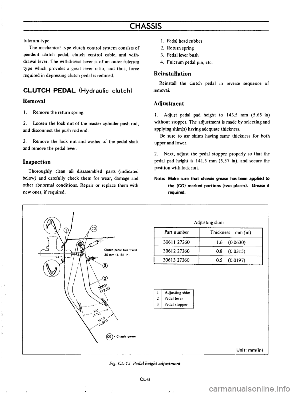
I
Adjust
pedal
pad
height
to
143
5
mm
5
65
in
without
stopper
The
adjustment
is
made
by
selecting
and
applying
shim
s
having
adequate
thickness
Be
sure
to
use
shims
having
same
thickness
for
both
upper
and
lower
2
Next
adjust
the
pedal
stopper
properly
so
that
the
pedal
pad
height
is
141
5
mm
5
57
in
and
secure
the
position
with
lock
nut
Note
Make
sure
that
chassis
grease
has
been
applied
to
the
leG
marked
portions
two
places
Grease
if
required
Adjusting
shim
Part
number
Thickness
mm
in
30611
27260
30612
27260
30613
27260
1
6
0
0630
0
8
0
0315
0
5
0
0197
I
2
3
Adjusting
shim
Pedal
lever
Pedal
stopper
Unit
mm
inl
Fig
CL
J5
Pedal
height
adjustment
CL
6