1973 DATSUN B110 engine oil capacity
[x] Cancel search: engine oil capacityPage 7 of 513
AUTOMATIC
TRANSMISSION
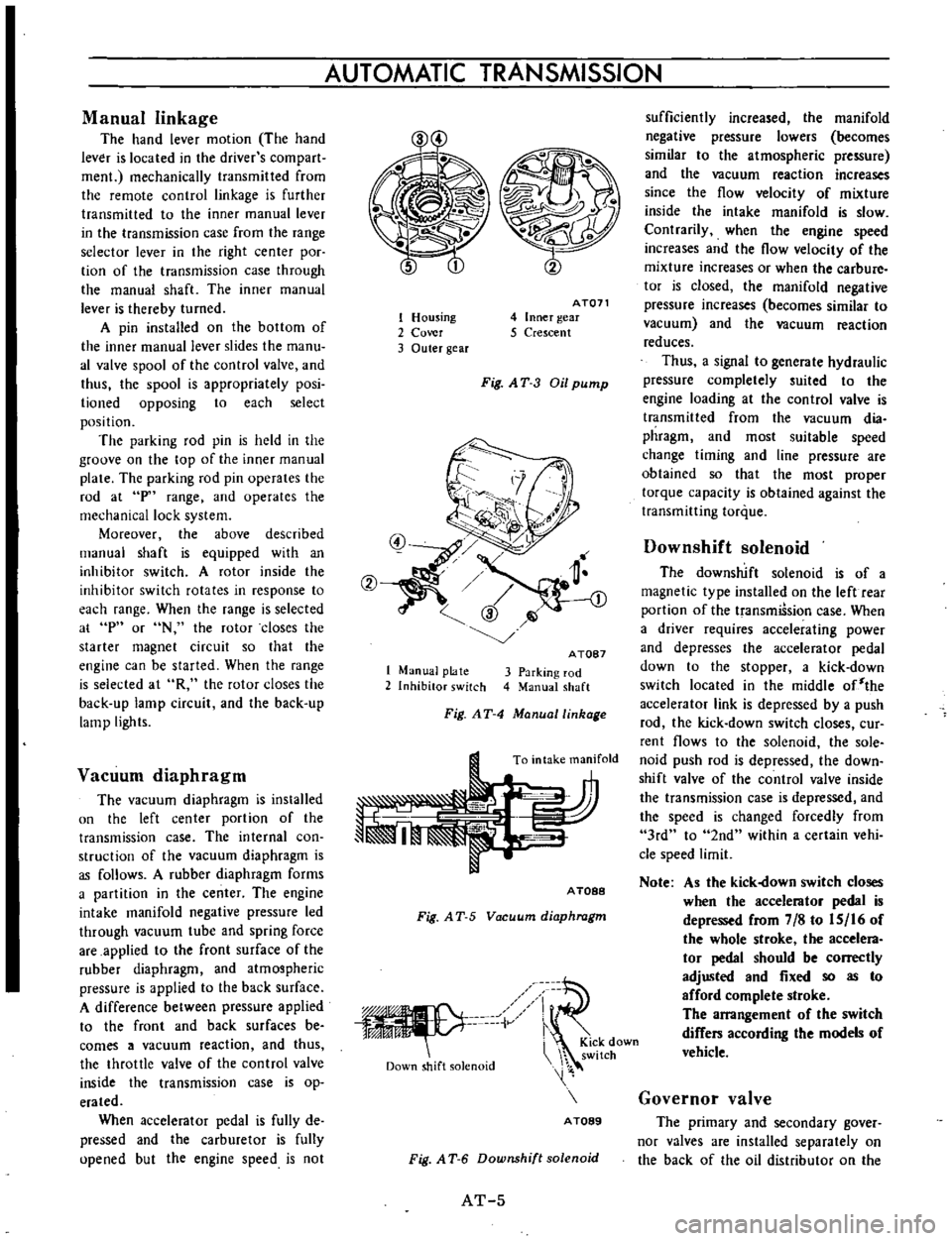
Manual
linkage
The
hand
lever
motion
The
hand
lever
is
located
in
the
driver
s
com
part
men
mechanically
transmitted
from
the
remote
control
linkage
is
further
transmitted
to
the
inner
manual
lever
in
the
transmission
case
from
the
range
selector
lever
in
the
right
center
poc
tion
of
the
transmission
case
through
the
manual
shaft
The
inner
manual
lever
is
thereby
turned
A
pin
installed
on
the
bottom
of
the
inner
manual
lever
slides
the
manu
al
valve
spool
of
the
control
valve
and
thus
the
spool
is
appropriately
posi
lioned
opposing
to
each
select
position
The
parking
rod
pin
is
held
in
the
groove
on
the
top
of
the
inner
manual
plate
The
parking
rod
pin
operates
the
rod
at
p
range
and
operates
the
mechanical
lock
system
Moreover
the
above
described
manual
shaft
is
equipped
with
an
inhibitor
switch
A
rotor
inside
the
inhibitor
switch
rotates
in
response
to
each
range
When
the
range
is
selected
at
p
or
N
the
rotor
closes
the
starter
magnet
circuit
so
that
the
engine
can
be
started
When
the
range
is
selected
at
R
the
rotor
closes
the
back
up
lamp
circuit
and
the
back
up
lamp
lights
Vacuum
diaphragm
The
vacuum
diaphragm
is
installed
un
the
left
center
portion
of
the
transmission
case
The
internal
con
struction
of
the
vacuum
diaphragm
is
as
follows
A
rubber
diaphragm
forms
a
partition
in
the
center
The
engine
intake
manifold
negative
pressure
led
through
vacuum
tube
and
spring
force
are
applied
to
the
front
surface
of
the
rubber
diaphragm
and
atmospheric
pressure
is
applied
to
the
back
surface
A
difference
between
pressure
applied
to
the
front
and
back
surfaces
be
comes
a
vacuum
reaction
and
thus
the
throttle
valve
of
the
control
valve
inside
the
transmission
case
is
op
erated
When
accelerator
pedal
is
fully
de
pressed
and
the
carburetor
is
fully
upened
but
the
engine
speed
is
not
1
Housing
2
Cover
3
Outer
gear
AT071
4
Inner
gear
5
Crescent
Fig
AT
3
Oil
pump
1
Manual
plate
2
Inhibitor
switch
A
TOB7
3
Parking
rod
4
Manual
shaft
Fig
AT
4
Manuallinhage
To
intake
manifold
A
TOBB
Fig
A
T
5
Vacuum
diaphragm
iV
Down
shift
solenoid
i
KiCk
down
switch
A
TOB9
Fig
A
T
6
Downshift
solenoid
AT
5
sufficiently
increased
the
manifold
negative
pressure
lowers
becomes
similar
to
the
atmospheric
pressure
and
the
vacuum
reaction
increases
since
the
flow
velocity
of
mixture
inside
the
intake
manifold
is
slow
Contrarily
when
the
engine
speed
increases
and
the
flow
velocity
of
the
mixture
increases
or
when
the
carbure
tor
is
closed
the
manifold
negative
pressure
increases
becomes
similar
to
vacuum
and
the
vacuum
reaction
reduces
Thus
a
signal
to
generate
hydraulic
pressure
completely
suited
to
the
engine
loading
at
the
control
valve
is
transmitted
from
the
vacuum
dia
phragm
and
most
suitable
speed
change
timing
and
line
pressure
are
obtained
so
that
the
most
proper
torque
capacity
is
obtained
against
the
transmitting
torque
Downshift
solenoid
The
downshift
solenoid
is
of
a
magnetic
type
installed
on
the
left
rear
portion
of
the
transmiSsion
case
When
a
driver
requires
accelerating
power
and
depresses
the
accelerator
pedal
down
to
the
stopper
a
kick
down
switch
located
in
the
middle
of
the
accelerator
link
is
depressed
by
a
push
rod
the
kick
down
switch
closes
cur
rent
flows
to
the
solenoid
the
sole
noid
push
rod
is
depressed
the
down
shift
valve
of
the
control
valve
inside
the
transmission
case
is
depressed
and
the
speed
is
changed
forcedly
from
3rd
to
2nd
within
a
certain
vehi
cle
speed
limit
Note
As
the
kick
own
switch
closes
when
the
accelerator
pedal
is
depressed
from
7
8
to
IS
16
of
the
whole
stroke
the
accelera
tor
pedal
should
be
correctly
adjusted
and
fixed
so
as
to
afford
complete
stroke
The
arrangement
of
the
switch
differs
according
the
models
of
vehicle
Governor
valve
The
primary
and
secondary
gover
nor
valves
are
installed
separately
on
the
back
of
the
oil
distributor
on
the
Page 14 of 513

against
the
throttle
pressure
16
When
performing
the
kick
down
the
SOV
moves
a
high
line
pressure
is
led
to
the
circuit
19
from
the
line
pressute
circuit
13
which
had
been
drained
the
plug
is
depressed
toward
the
left
and
the
circuit
19
becomes
equal
to
the
line
pressure
13
Thus
the
kick
down
is
performed
Preasure
modifier
valve
PMV
In
comparison
with
the
operating
pressure
required
in
starting
the
vehi
ele
power
transmitting
capacity
of
the
clutch
in
other
words
required
op
erating
pressure
may
be
lower
when
the
vehicle
is
once
started
When
the
line
pressure
is
retained
in
a
high
level
up
to
a
high
vehicle
speed
a
shock
generated
from
the
shifting
increases
and
the
oil
pump
loss
also
increases
In
order
to
prevent
the
above
described
defective
occurrences
with
the
opera
lion
of
the
governor
pressure
15
the
throttle
pressure
must
be
changed
over
to
reduce
the
line
pressure
The
PMV
is
used
for
this
purpose
When
the
governor
pressure
15
which
is
applied
to
the
right
side
of
the
PMV
is
low
the
valve
is
depressed
toward
the
right
by
the
throttle
pres
sure
16
applied
to
the
area
differ
ence
of
the
value
and
the
spring
force
and
the
circuit
from
the
circuit
16
to
the
circuit
18
is
closed
However
when
the
vehicle
speed
increases
and
the
governor
pressure
15
exceeds
a
certain
level
the
governor
pressure
toward
the
left
which
is
applied
to
the
right
side
exceeds
the
spring
force
and
the
throttle
pressure
16
toward
the
right
the
valve
is
depressed
toward
the
left
and
the
throttle
pressure
is
led
from
the
circuit
16
to
the
circuit
18
This
throttle
pressure
18
is
applied
to
the
top
of
the
PRY
and
pressure
of
the
line
pressure
source
7
is
reduced
Contrarily
when
the
vehi
cle
speed
lowers
and
the
governor
pressure
15
lowers
the
force
toward
the
right
exceeds
the
governor
pres
CHASSIS
sure
the
valve
is
depressed
back
to
ward
the
right
the
throttle
pressure
18
is
drained
to
the
spring
unit
This
valve
is
switched
when
the
throttle
pressure
and
the
governor
pressure
are
high
or
when
the
throttle
pressure
is
low
and
the
governor
pres
sure
is
low
II
18
16
1JU
k
I
15
AT099
Fig
AT
14
Pressure
modifier
valve
Vacuum
throttle
valve
VTV
The
vacuum
throttle
valve
is
a
regulator
valve
which
uses
the
line
pressure
7
for
the
pressure
source
and
regulates
the
throttle
pressure
16
which
is
proportioned
to
the
force
of
the
vacuum
diaphragm
The
vacuum
diaphragm
varies
depending
on
the
engine
throttle
condition
negative
pressure
in
the
intake
line
When
the
line
pressure
7
is
ap
plied
to
the
bottom
through
the
valve
hole
and
the
valve
is
depressed
up
ward
space
from
the
line
pressure
7
to
the
throttle
pressure
16
is
closed
and
the
space
from
the
throttle
pres
sure
16
to
the
drain
circuit
17
is
about
to
open
In
this
the
throttle
pressure
16
becomes
lower
than
the
line
pressure
7
by
the
pressure
equivalent
to
the
pressure
loss
of
the
space
and
the
force
to
depress
through
the
rod
of
the
vacuum
dia
phragm
is
balanced
with
the
throttle
pressure
16
applied
upward
to
the
bottom
When
the
engine
torque
is
high
the
negative
pressure
in
the
intake
line
rises
similar
to
the
atmospheric
pres
sure
and
the
force
of
the
rod
to
depress
the
valve
increases
As
the
result
the
valve
is
depressed
down
ward
the
space
from
the
throttle
pressure
16
to
the
drain
17
re
AT
lO
duces
and
the
space
from
the
line
pressure
7
to
the
throttle
pressure
16
increases
Consequently
the
throttle
pressure
16
increases
and
the
valve
is
baI
anced
Contrarily
when
the
engine
torque
lowers
and
the
negative
pres
sure
in
the
intake
line
lowers
similar
to
vacuum
force
of
the
rod
to
de
press
the
valve
lowers
and
the
throttle
pressure
16
also
lowers
When
a
pressure
regulated
by
the
throttle
back
up
valve
described
in
the
subse
quent
paragraph
is
led
to
the
circuit
17
a
high
pressure
is
applied
through
the
space
from
the
circuit
17
to
the
throttle
pressure
16
Consequently
the
VTV
is
unbalanced
the
throttle
pressure
16
becomes
equal
to
the
back
up
ptessure
17
and
the
valve
is
locked
upward
bi
II
I
ATlOa
Fig
AT
15
Vacuum
throttle
valve
Throttle
back
up
valve
TBV
Usually
this
valve
is
depressed
downward
by
the
spring
force
and
the
circuit
17
is
drained
upward
As
soon
as
the
lever
is
shfted
either
to
2
or
range
line
pressure
is
led
from
the
circuit
4
the
line
pressure
is
applied
to
the
area
differ
ence
of
the
valve
the
valve
is
depres
sed
upward
the
space
from
the
circuit
Page 64 of 513

CHASSIS
SERVICE
DATA
AND
SPECIFICATIONS
General
specifications
Torque
converter
Type
Stall
torque
ratio
Transmission
Type
Control
elements
Gear
ratio
Selector
positions
Oil
pump
Type
Number
of
pump
Oil
Capacity
Hydraulic
control
system
Lubrication
system
Cooling
system
Multiple
disc
clutch
Band
brake
Multiple
disc
brake
One
way
clutch
1st
lnd
3rd
Reverse
P
Park
R
Reverse
N
Neutral
D
Drive
1
lnd
lock
I
Lock
up
AT
60
Symmetrical3
element
I
stage
l
phase
torque
converter
coupling
2
0
I
3
speed
forward
and
one
speed
reverse
with
planetary
gear
train
1
I
I
I
2
458
1
458
1
000
2
182
The
transmission
is
placed
in
neutral
The
output
shaft
is
fixed
The
engine
can
be
started
Backward
running
The
transmission
is
in
neutral
The
engine
can
be
started
Up
or
downshifts
automatically
to
and
from
1st
lnd
and
top
Fixed
at
2nd
Fixed
at
low
or
downshifts
from
2nd
Internally
intermeslting
involute
gear
pump
Automatic
transmission
fluid
Dexron
type
5
5
liters
57
8
U
S
qts
47
8
Imp
qts
Approximately
1
7
liters
27
8
U
S
qts
2
3
8
Imp
qts
in
torque
converter
Controlled
by
detecting
the
negative
pressure
of
intake
manifold
and
the
revolution
speed
of
output
shaft
Forced
lubrication
by
an
oil
pwnp
Air
cooled
Page 268 of 513
BODY
ELECTRICAL
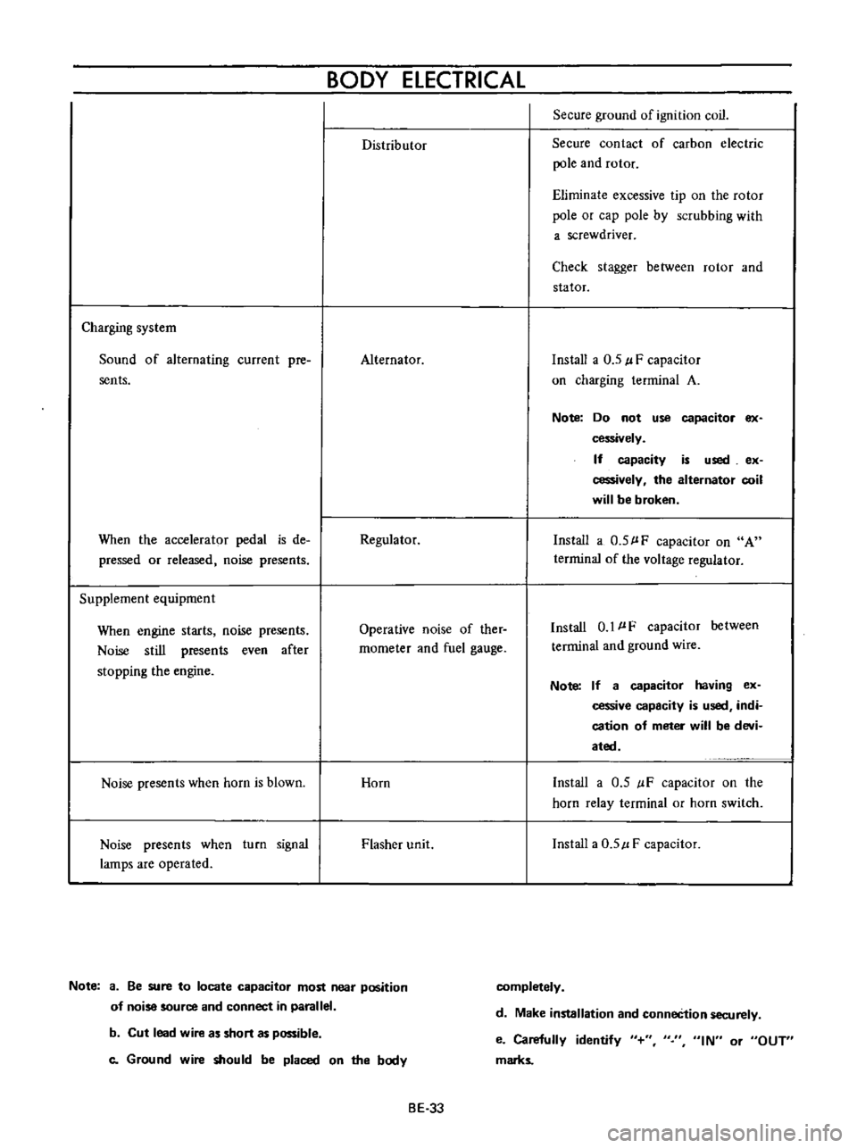
Distributor
Secure
ground
of
ignition
coil
Secure
contact
of
carbon
electric
pole
and
rotor
Eliminate
excessive
tip
on
the
rotor
pole
or
cap
pole
by
scrubbing
with
a
screwdriver
Check
stagger
between
rotor
and
stator
Charging
system
Sound
of
alternating
current
pre
sents
Alternator
Install
a
0
5
l
F
capacitor
on
charging
terminal
A
Note
Do
not
use
capacitor
ex
cessively
If
capacity
is
used
ex
cessively
the
alternator
coil
will
be
broken
When
the
accelerator
pedal
is
de
pressed
or
released
noise
presents
Regulator
Install
a
0
5
l
F
capacitor
on
A
terrninal
of
the
voltage
regulator
Supplement
equipment
When
engine
starts
noise
presents
Noise
still
presents
even
after
stopping
the
engine
Operative
noise
of
ther
rnometer
and
fuel
gauge
Install
0
1
l
F
capacitor
between
terminal
and
ground
wire
Note
If
a
capacitor
having
ex
cessive
capacity
is
used
indi
cation
of
meter
will
be
devi
ated
Noise
presents
when
horn
is
blown
Horn
Install
a
0
5
IF
capacitor
on
the
horn
relay
terminal
or
horn
switch
Noise
presents
when
turn
signal
lamps
are
operated
Flasher
unit
Install
a
0
5
l
F
capacitor
Note
a
Be
sure
to
locate
capacitor
most
near
position
of
noise
source
and
connect
in
parallel
completely
d
Make
installation
and
conneCtion
securely
b
Cut
lead
wire
as
short
as
possible
c
Ground
wire
should
be
placed
on
the
body
e
Carefully
identify
marks
IN
or
OUT
BE
33
Page 307 of 513
ENGINE
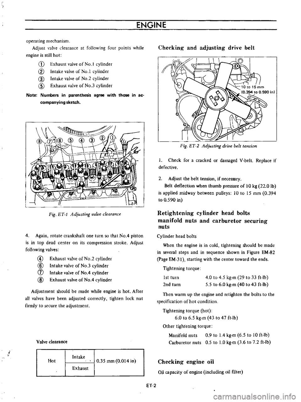
operating
mechanism
Adjust
valve
clearance
at
following
four
points
while
engine
is
still
hot
G
Exhaust
valve
of
No
1
cylinder
CV
Intake
valve
of
No
1
cylinder
CID
Intake
valve
of
No
2
cylinder
CID
Exhaust
valve
of
No
3
cylinder
Note
Numbers
in
parenthesis
agree
with
those
in
ac
companying
sketch
I
Fig
BY
1
Adjusting
valve
clearance
4
Again
rotate
crankshaft
one
turn
so
that
No
4
piston
is
in
top
dead
ce
lter
on
its
compression
stroke
Adjust
follnwing
valves
@
Exhaust
valve
of
No
2
cylinder
@
Intake
valve
of
No
3
cylinder
f
Intake
valve
of
No
4
cylinder
@
Exhaust
valve
of
No
4
cylinder
Adjustment
should
be
made
while
engine
is
hot
After
all
valves
have
been
adjusted
correctly
tighten
lock
nut
firmly
to
secure
the
adjustment
Vah
e
clearance
Hot
Intake
0
35
mm
0
014
in
Exhaust
Checking
and
adjusting
drive
belt
II
I
Fig
ET
2
Adjusting
drive
belt
tension
I
Check
for
a
cracked
or
damaged
V
belt
Replace
if
defective
2
Adjust
the
belt
tension
if
necessary
Belt
deflection
when
thumb
pressure
of
10
kg
22
0
lb
is
applied
midway
between
pulleys
10
to
15
mm
0
394
to
0
590
in
Retightening
cylinder
head
bolts
manifold
nuts
and
carburetor
securing
nuts
Cylinder
head
bolts
When
the
engine
is
in
cold
tightening
should
be
made
in
several
steps
and
in
sequence
shown
in
Figure
EM
82
page
EM
31
starting
with
the
center
toward
the
ends
Tightening
torque
1st
turn
2nd
turn
4
0
to
4
5
kg
m
29
to
33
ft
lb
5
5
to
6
0
kg
m
40
to
43
ft
lb
Then
warm
up
the
engine
and
retighten
the
bolts
to
the
specification
of
hot
condition
Tightening
torque
hot
6
0
to
6
5
kg
m
43
to
47
ft
lb
Other
tightening
torque
Manifold
nuts
0
9
to
14
kg
m
6
5
to
10
ft
lb
Carburetor
nuts
0
5
to
LO
kg
m
3
6
to
7
2
ft
lb
Checking
engine
oil
Oil
capacity
of
engine
including
oil
filter
ET
2
Page 308 of 513
EMISSION
CONTROL
AND
TUNE
UP
Capacity
Maximum
3
3
L
X
US
gal
y
Imp
gal
2
3
L
US
gal
f
Imp
gal
Minimum
Make
sure
that
engine
oil
is
not
deteriorated
with
cooling
water
or
gasoline
Drain
and
refill
the
oil
if
necessary
Notes
a
A
milky
oil
indicates
the
presence
of
cooling
water
Find
the
cause
for
necessary
corrective
action
b
Oil
with
extremely
low
viscosity
indicates
dilution
with
gasoline
2
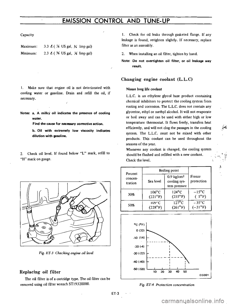
Check
oil
level
If
found
below
L
mark
refill
to
H
mark
on
gauge
Fig
ET
3
Checking
engine
oil
level
Replacing
oil
filter
The
oil
ftIter
is
of
a
cartridge
type
The
oil
filter
can
be
removed
using
oil
ftIter
wrench
STl9320000
Check
for
oil
leaks
through
gasketed
flange
If
any
leakage
is
found
retighten
slightly
If
necessary
replace
filter
as
an
assembly
2
When
installing
an
oil
filter
tighten
by
hand
Note
Do
not
overtighten
oil
filter
or
oil
leakage
way
result
Changing
engine
coolant
L
L
C
Nissan
long
life
coolant
LLC
is
an
ethylene
glycol
base
product
containing
chemical
inhibitors
to
protect
the
cooling
system
from
rusting
and
corrosion
The
L
L
C
does
not
contain
any
glycerine
ethyl
or
methyl
alcohol
It
will
not
evaporate
or
boil
away
and
can
be
used
with
either
high
or
low
temperature
thermostat
It
flows
freely
transfers
heat
efficiently
and
will
not
clog
the
passages
in
the
cooling
system
The
LL
C
must
not
be
mixed
with
other
products
This
coolant
can
be
used
throughout
tlie
seasons
of
the
year
Whenever
any
coolant
is
changed
the
cooling
system
should
be
flushed
and
refilled
with
a
new
coolant
Check
the
level
J
Percent
Boiling
point
0
9
kgfcm2
Freeze
concen
tration
Sea
level
cooling
sys
protection
tern
pressure
30
1060
C
I
240C
15OC
221OF
255OF
5OF
50
IUY
C
1270C
35
C
2280
F
2610F
3IOF
DC
OF
0
321
10
14
20141
50
58
I
I
I
I
1
I
I
1
30
1
22
40
401
40
10
30
50
20
EGOOl
Fig
ET
4
Protection
concentration
ET
3
Page 309 of 513

ENGINE
Checking
cooling
system
hoses
and
connections
Check
cooling
system
hoses
and
fiHings
for
loose
connections
and
deterioration
Retighten
or
replace
as
necessary
Inspection
of
radiator
cap
Apply
reference
pressure
0
9
kg
cm1
13
psi
to
radiator
cap
by
means
of
a
cap
tester
to
see
if
it
is
in
good
condition
Replace
cap
assembly
if
necessary
ET012
Fig
ET
5
Testing
radiator
cap
Cooling
system
pressure
test
With
radiator
cap
removed
apply
reference
pressure
1
6
kg
cm1
23
psi
to
the
cooling
system
bv
means
of
a
tester
to
check
for
leaks
at
the
system
compo
nents
Water
capacity
with
heater
4
9
l
I
Y
US
gal
l
i
Imp
gal
without
heater
4
2
l
I
i
US
gal
i
Imp
gal
Fig
ET
6
Testing
cooling
system
pressure
Checking
vaccum
fittings
hoses
and
connections
Check
vacuum
system
fittings
and
hoses
for
loose
connections
and
deterioration
Retighten
if
necessary
replace
any
deteriorated
parts
Checking
engine
compression
Compression
pressure
test
Note
To
test
cylinder
compression
remove
all
spark
plugs
and
hold
tester
fitting
tightly
in
spark
plug
hole
of
cylinder
The
tester
is
used
to
determine
whether
cylinder
can
hold
compression
or
whether
there
is
excessive
leakage
past
rings
etc
I
Td10
l
y
Fig
ET
7
Testing
compression
pressure
Test
compression
with
engine
warm
all
spark
plugs
removed
and
throttle
and
choke
valve
opened
No
cylinder
compression
should
be
less
than
80
of
highest
cylinder
s
Excessive
variation
between
cyl
inders
accompanied
by
low
speed
missing
of
the
cylinder
usually
indicates
a
valve
not
properly
seating
or
a
broken
piston
ring
Low
pressures
even
though
uniform
may
indicate
worn
rings
This
may
be
accompanied
by
excessive
oil
consumption
Test
conclusion
If
one
or
more
cylinders
read
low
inject
about
one
tablespoon
of
enigne
oil
on
top
of
the
pistons
in
low
ET
4
Page 327 of 513
ENGINE
6
Start
the
engine
and
continue
idling
as
described
under
paragraphs
I
2
and
3
above
When
several
minutes
have
passed
and
the
valve
is
partially
opened
read
the
thermister
indication
It
is
correct
if
the
reading
falls
between
380C
1000
F
and
550C
1300
F
If
the
reading
is
abnormal
replace
the
sensor
7
On
the
engine
equipped
with
an
idle
compensator
as
service
option
do
as
follows
before
replacing
the
sensor
Clog
hose
on
idle
compensator
side
by
twisting
or
clamping
it
and
check
the
temperature
as
given
in
paragraphs
5
and
6
above
If
the
thermometer
shO
vs
correct
temperature
replace
the
idle
compensa
tOf
if
the
reading
is
abnormal
replace
the
sensor
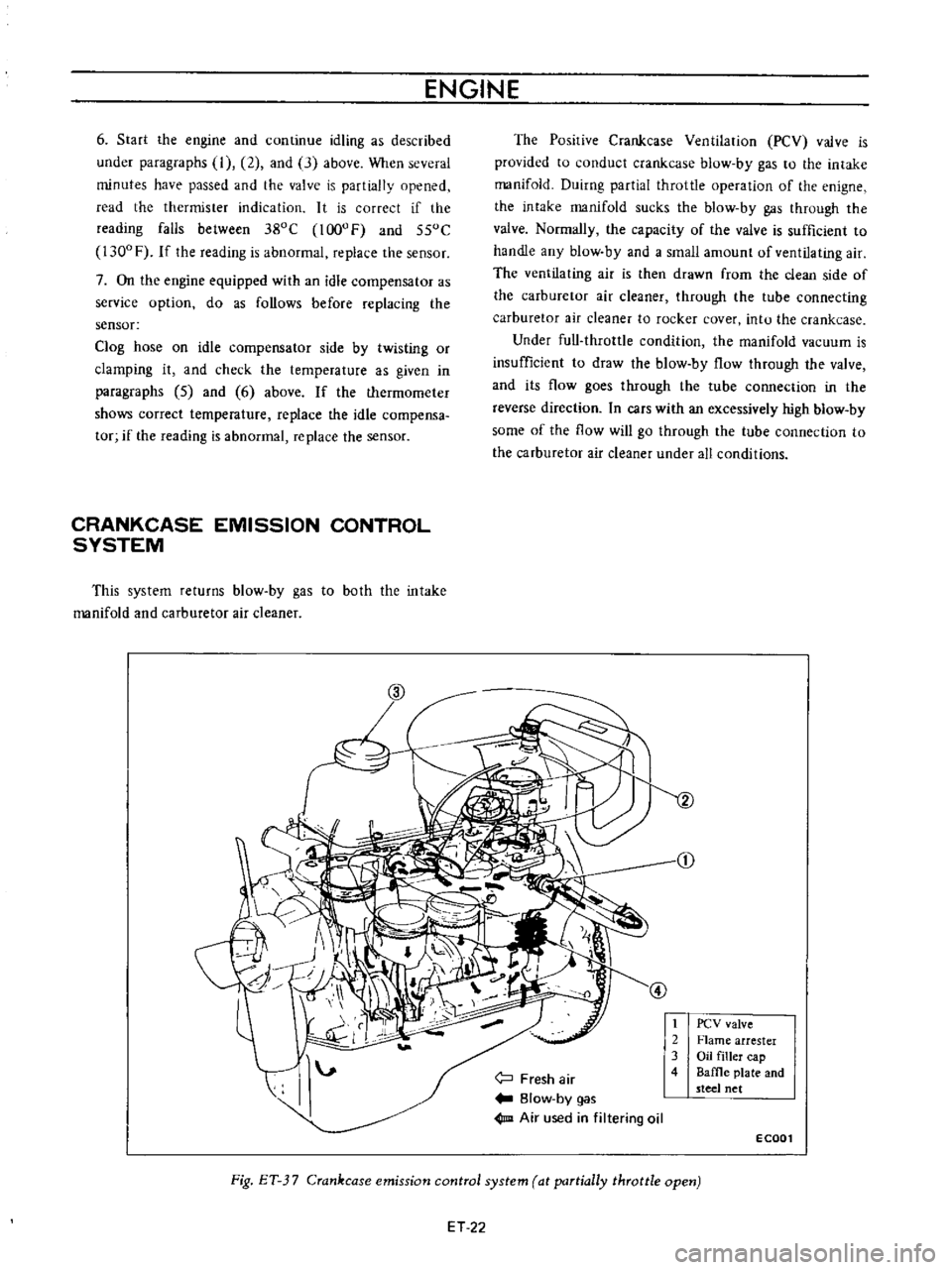
CRANKCASE
EMISSION
CONTROL
SYSTEM
This
system
returns
blow
by
gas
to
both
the
intake
manifold
and
carburetor
air
cleaner
The
Posirive
Crankcase
Ventilation
PCV
valve
is
provided
to
conduct
crankcase
blow
by
gas
to
the
intake
manifold
Duirng
partial
throttle
operation
of
the
enigne
the
intake
manifold
sucks
the
blow
by
gas
through
the
valve
Normally
the
capacity
of
the
valve
is
sufficient
to
handle
any
blow
by
and
a
small
amount
of
ventilating
air
The
ventilating
air
is
then
drawn
from
the
clean
side
of
the
carburetor
air
cleaner
through
the
tube
connecting
carburetor
air
cleaner
to
rocker
cover
intu
the
crankcase
Under
full
throttle
condition
the
manifold
vacuum
is
insufficient
to
draw
the
blow
by
flow
through
the
valve
and
its
flow
goes
through
the
tube
connection
in
the
reverse
direction
In
cars
with
an
excessively
high
blow
by
some
of
the
flow
will
go
through
the
tube
connection
to
the
carburetor
air
cleaner
under
all
conditions
j
Fresh
air
Blow
by
gas
1m
Air
used
in
filtering
oil
t
2
3
4
PCV
valve
Flame
arrester
Oil
filler
cap
Baffle
plate
and
steel
net
ECOOl
Fig
ET
3
7
Crankcase
emission
control
system
at
partially
throttle
open
ET
22