1973 DATSUN B110 brakes
[x] Cancel search: brakesPage 53 of 513

AUTOMATIC
TRANSMISSIO
N
TROUBLE
DIAGNOSES
AND
ADJUSTMENT
INSPECTION
AND
ADJUSTMENT
BEFORE
TROUBLE
DIAGNOSIS
Testing
instrument
for
inspection
Checking
oil
level
Inspection
and
repair
of
oil
leakage
Checking
engine
idling
rpm
Checking
and
adjusting
kick
down
switch
and
downshift
solenoid
Inspection
and
adjustment
of
manual
linkage
Checking
and
adjusting
inhibitor
switch
STALL
TEST
Stall
test
procedures
Judgement
As
the
troubles
on
the
automatic
transmission
can
be
mostly
repaired
by
doing
simple
adjustment
so
do
not
disassemble
immediately
if
the
auto
m
tic
transmission
is
in
trouble
Firstly
inspect
and
adjust
the
auto
matic
transmission
with
mounting
on
vehicle
by
observing
the
trouble
shooting
chart
If
the
trouble
could
not
be
solved
by
this
procedure
then
remove
and
disassemble
the
automatic
transmis
sion
It
is
advisable
to
check
overhaul
and
repair
each
point
in
the
order
itemized
in
the
trouble
shooting
chart
l
In
the
trouble
shooting
chart
the
diagnosis
items
are
arranged
in
the
order
from
easy
to
difficult
and
there
fore
please
follow
these
items
The
transmission
should
not
be
removed
unless
necessary
2
The
test
and
adjustment
for
trou
ble
diagnosis
should
be
made
on
the
basis
of
standard
values
and
the
data
should
be
recorded
ROAD
TEST
Car
speed
at
gear
shift
Checking
speed
changing
condition
Checking
items
during
speed
change
Shift
schedule
LINE
PRESSURE
TEST
Line
pressure
governor
feed
pressure
Judgement
in
measuring
line
pressure
TROUBLE
SHOOTING
CHART
Inspecting
items
Trouble
shooting
chart
for
3N71
B
Automatic
Transmission
Trouble
shooting
guide
for
3N718
Automatic
Transmission
CONTENTS
AT
49
AT
49
AT
49
AT
50
AT
50
AT
50
AT
51
AT
51
AT
51
AT51
AT
52
INSPECTION
AND
AD
JUSTMENT
BEFORE
TROUBLE
DIAGNOSIS
Testing
instrument
for
inspection
1
Engine
tachometer
2
Vacuum
gauge
3
Oil
pressure
gauge
It
is
convenient
to
install
these
instruments
in
a
way
that
allows
meas
urements
to
be
made
from
the
driver
s
seat
Checking
oil
level
In
checking
the
automatic
transmis
sion
the
oil
level
and
the
condition
of
oil
around
the
oil
level
gauge
should
be
examined
every
5
000
km
3
000
miles
These
steps
are
easy
and
effec
live
in
trouble
shooting
as
some
change
of
oil
conditions
are
linked
with
developed
troubles
in
many
cases
AT
49
AT
52
AT
52
AT
53
AT
53
AT
53
AT
53
AT
53
AT
54
AT
54
AT
54
AT
55
AT
5B
For
instance
Lack
of
oil
causes
defective
opera
tion
by
making
the
clutches
and
brakes
slip
developing
severe
wear
The
cause
of
this
operation
is
that
the
oil
pump
has
begun
to
suck
air
which
caused
oil
foaming
thus
rapidly
deteriora
ting
the
oil
quality
and
pro
ducing
sludge
and
varnish
Meanwhile
excessive
oil
is
also
bad
as
in
the
case
of
a
lack
of
oil
because
of
oil
foaming
by
being
stirred
up
by
the
gears
Moreover
in
high
speed
driving
with
excessive
oil
in
the
trans
mission
the
oil
often
blows
out
from
the
breather
I
Measuring
oil
level
When
checking
the
fluid
level
start
the
engine
and
run
it
until
normal
operating
temperatures
oil
tempera
ture
50
to
800e
122
to
176
F
Approximately
ten
minute
operation
will
elevate
the
temperature
to
this
range
and
enigne
idling
conditions
are
stabilized
Then
apply
the
brakes
and
move
the
transmission
shift
lever
Page 126 of 513

CHASSIS
DESCRIPTION
The
Datsun
1200
series
new
models
adopt
a
hydraulic
brake
Dis
brake
or
two
leading
shoe
type
drum
brake
is
used
for
the
front
wheels
and
leading
trailing
shoe
type
drum
brake
is
used
for
the
rear
wheels
With
adoption
of
the
disc
brake
safety
at
high
speed
range
driving
is
further
improved
For
the
master
cylinder
either
single
type
or
tandem
type
is
used
There
are
two
types
of
tandem
type
master
cylinder
one
is
for
disc
brake
and
the
other
for
drum
brake
Under
the
standard
specifications
h0wever
the
tandem
type
master
cylinder
is
used
for
disc
brake
and
single
type
is
used
for
drum
brake
The
tandem
master
cylinder
provides
a
dual
brake
system
improving
safety
The
hand
brake
is
of
a
mechanical
type
which
brakes
the
rear
wheels
through
the
control
lever
and
steel
wire
The
control
lever
is
located
between
the
driver
and
assistant
seats
and
can
be
operated
easily
BRAKE
PEDAL
The
steering
colunm
bracket
supports
the
brake
pedaL
The
brake
pedal
is
instaUed
on
the
steering
column
bracket
with
a
fulcrum
pin
The
brake
pedal
arm
and
brake
master
cylinder
push
rod
are
joined
with
a
clevis
pin
The
stop
lamp
switch
opposes
the
brake
pedal
arm
bracket
and
operates
as
the
pedal
arm
moves
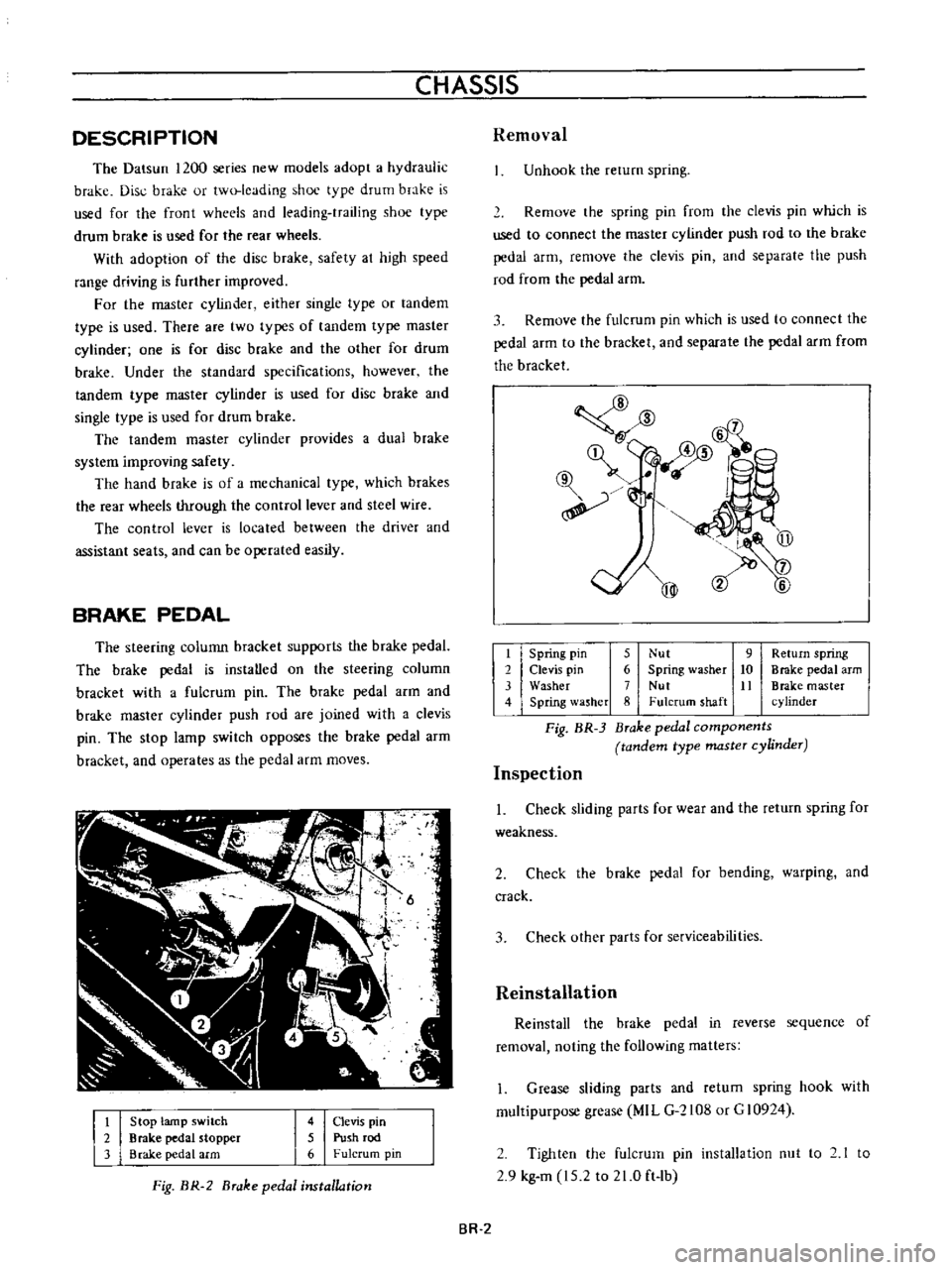
t
2
3
Stop
lamp
switch
Brake
pedal
stopper
Brake
pedal
arm
4
Clevis
pin
5
Push
rod
6
Fulcrum
pin
Fig
BR
2
Brake
pedal
installation
Removal
Unhook
the
rerum
spring
Remove
the
spring
pin
from
the
clevis
pin
which
is
used
to
connect
the
master
cylinder
push
rod
to
the
brake
pedal
arm
remove
the
clevis
pin
and
separate
the
push
rod
from
the
pedal
arm
3
Remove
the
fulcrum
pin
which
is
used
to
connect
the
pedal
arm
to
the
bracket
and
separate
the
pedal
arm
from
the
bracket
@
mm
l6
qf
@
@
t
Spring
pin
5
Nut
9
Return
spring
2
Clevis
pin
6
Spring
washer
10
Brake
pedal
arm
3
Washer
7
Nut
It
Brake
master
4
Spring
lasher
8
Fulcrum
shaft
cylinder
Fig
BR
3
Brake
pedal
components
tandem
type
master
cylinder
Inspection
1
Check
sliding
parts
for
wear
and
the
return
spring
for
weakness
2
Check
the
brake
pedal
for
bending
warping
and
crack
3
Check
other
parts
for
serviceabilities
Reinstallation
Reinstall
the
brake
pedal
in
reverse
sequence
of
removal
noting
the
following
matters
1
Grease
sliding
parts
and
retum
spring
hook
with
multipurpose
grease
MIL
G
2108
or
G
10924
2
Tighten
the
fulcrum
pin
installation
nut
to
2
1
to
2
9
kg
m
15
2
to
21
0
ft
lb
BR
2
Page 131 of 513

Tightening
torque
3
way
connector
1
5
to
1
8
kg
m
10
8
to
13
0
ft
lh
1
5
to
1
8
kg
m
10
8
to
13
0
ft
lh
1
5
to
1
8
kg
m
10
8
to
13
0
ft
lb
0
7
to
0
9
kg
m
5
1
to
6
5
ft
1b
Master
cylinder
Brake
hose
Air
bleeder
5
Fill
the
master
cylinder
brake
fluid
reservoir
with
brake
fluid
and
perform
air
bleeding
complele1y
Note
a
Do
not
use
brake
fluid
other
than
specified
b
The
specified
brake
fluid
is
used
for
both
single
and
tandem
type
master
cylinders
6
Upon
completion
of
air
bleeding
make
sure
that
the
brake
operates
correctly
and
check
the
brake
tube
and
hose
connectors
for
fluid
leaking
Fully
depress
the
brake
pedal
continue
to
depress
the
brake
pedal
for
several
seconds
and
make
sure
that
no
brake
fluid
leaks
from
any
part
of
the
brake
line
Replace
defective
part
if
required
Brake
line
pressure
differential
warning
light
switch
A
warning
light
is
located
on
the
instrument
panel
to
warn
the
driver
when
a
pressure
difference
of
13
to
17
kg
cm2
185
to
2421bJsq
in
exists
between
the
front
and
rear
b
rake
systems
A
hydraulically
actuated
warning
light
switch
is
located
in
the
engine
compartment
Both
front
and
rear
brake
systems
are
connected
to
this
switch
assembly
When
a
pressure
difference
of
13
to
17
kgJcm2
185
to
242
lbJsq
in
occurs
between
the
front
and
rear
brake
systems
the
valves
will
shuttle
toward
the
side
with
the
low
pressure
The
valve
contacts
with
the
switch
terminal
BRAKE
the
ground
circuit
for
the
warning
light
is
completed
and
thus
the
warning
light
lights
In
this
case
correct
the
hydraulic
brake
problem
and
bleed
the
brakes
Check
the
warning
light
switch
assembly
for
a
proper
operation
Check
the
switch
assembly
for
fluid
leakage
Note
Do
not
attempt
to
repair
switch
for
any
reason
replace
switch
assembly
completely
1
To
front
brake
L
H
2
From
master
cylinder
F
3
From
master
cylinder
R
4
To
rear
brake
L
B
R
M
5
To
front
brake
R
H
Fig
BR
12
Warning
light
switch
r
I
@
I
I
3
I
Valve
assembly
4
Piston
load
spring
Wire
terminal
Brake
tube
Fig
BR
13
Sectional
view
of
warning
light
switch
BR
7
Page 149 of 513

Pedal
yields
under
slight
pressure
Excessive
pedal
travel
All
brakes
drag
One
brake
drags
Unbalanced
brakes
BRAKE
Use
of
a
brake
fluid
with
a
boiling
point
which
is
too
low
Reservoir
filler
cap
ven
t
hole
clogged
This
promotes
a
vacuum
in
master
cylinder
that
sucks
in
air
through
rear
seal
Deteriorated
check
valve
External
leaks
Master
cylinder
leaks
through
primary
cap
System
has
not
been
bled
Improperly
adjusted
clearance
Fluid
level
in
master
cylinder
is
too
low
Thermal
expansion
of
drums
due
to
over
heating
Insufficient
shoe
tlrdrum
clearance
Weak
shoe
return
springs
Brake
shoe
return
no
free
travel
Seized
master
cylinder
piston
Loose
or
damaged
wheel
bearings
Weak
broken
or
unhooked
brake
shoe
return
springs
Insufficient
clearance
between
brake
shoe
and
drum
Grease
or
oil
on
linings
Seized
piston
in
wheel
cylinder
Tires
improperly
inflated
Loose
wheel
bearing
BR
25
Change
with
the
specified
brake
fluid
and
bleed
system
Clean
reservoir
filler
cap
and
bleed
the
system
Fit
a
new
check
valve
and
bleed
the
system
Check
master
cylinder
piping
and
wheel
cylinder
for
leaks
and
make
necessary
re
pairs
Overhaul
master
cylinder
Bleed
the
system
Adjust
shoe
to
drum
clearance
Full
up
with
specified
brake
fluid
Bleed
the
system
if
required
Allow
drums
to
cool
off
Check
brake
shoe
linings
and
drums
Replace
damaged
parts
Adjust
clearance
Replace
the
springs
Adjust
pedal
height
Service
the
master
cylinder
replace
the
piston
and
bleed
the
system
Adjust
or
replace
wheel
bearings
Replace
spring
Adjust
brakes
Clean
brake
mechanism
replace
lining
and
correct
cause
of
grease
or
oil
getting
on
lining
Service
the
wheel
cylinder
and
bleed
the
system
Inflate
tires
to
correct
pressure
Adjust
wheel
bearing
Page 150 of 513

CHASSIS
Front
suspension
faulty
Thoroughly
check
and
adjust
all
front
sus
pension
components
Excessive
pedal
pressure
required
poor
brakes
Grease
mud
or
water
on
linings
Remove
drums
Clean
and
dry
linings
or
replace
Full
area
of
linings
not
contacting
drums
Replace
shoes
Scored
brake
drums
Reface
drums
and
install
new
linings
Brake
chatter
squeak
or
squeal
Dust
on
drums
or
oil
soiled
linings
Remove
and
clean
drums
thoroughly
Eliminate
oil
leak
Weak
shoe
return
springs
Check
springs
and
replace
as
required
Drum
out
of
round
Turn
drums
on
lathe
Worn
linings
Replace
linings
SERVICE
JOURNAL
OR
BULLETIN
REFERENCE
DATE
JOURNAL
or
BULLETIN
No
PAGE
No
SUBJECT
BR
26
Page 178 of 513

CHASSIS
TROUBLE
DIAGNOSES
AND
CORRECTIONS
Condition
Heavy
steering
Loose
steering
PuU
to
one
side
Steering
shock
Probable
cause
Low
tire
pressure
Incorrect
front
wheel
alignment
Lack
of
lubricant
Firm
sticking
of
the
ball
joint
and
strut
bearing
Improper
adjustment
and
damage
of
steering
gear
housing
Hard
locking
of
column
bearing
Incorrect
front
wheel
bearing
adjustment
Loose
steering
linkage
connections
Loose
steering
gear
housing
mounting
Incorrect
adjustment
of
adjust
nut
Incorrect
tire
pressure
Incorrect
front
wheel
alignment
Incorrect
front
wheel
bearing
adjustment
Unequal
brake
adjustment
Weak
front
suspension
units
Deformation
or
improper
fitting
of
sus
pension
Incorrect
front
wheel
alignment
Loose
front
wheel
bearings
Loose
steering
linkage
connection
and
trans
verse
link
Incorrect
adjustment
of
ball
nut
Wheels
out
of
balance
ST
18
Corrective
action
Inflate
tires
to
recommended
pressure
Adjust
to
specifications
Lubricate
steering
gear
and
ball
joints
or
replace
worn
ball
joint
Replace
Adjust
or
replace
according
to
instructions
Lubricate
with
bearing
grease
Adjust
or
replace
as
required
Inspect
replace
worn
parts
if
any
and
tighten
nuts
to
recommended
torque
Tighten
mounting
bolts
to
proper
torque
Adjust
according
to
instructions
Inflate
to
recommended
pressure
Inspect
and
correct
front
wheel
alignment
Adjust
bearings
according
to
instructions
Adjust
brakes
Replace
Check
correct
or
replace
Inspect
and
correct
front
wheel
alignment
Adjust
bearings
Inspect
replace
worn
parts
if
any
and
tighten
nuts
to
proper
torque
Adjust
steering
gear
according
to
in
structions
Inspect
and
correct
wheel
balance