1973 DATSUN B110 ECU
[x] Cancel search: ECUPage 25 of 513
AUTOMATIC
TRANSMISSION
D
range
Low
gear
To
queCon
t
Front
Clutch
LOW
R
B
B
k
B
I
12
I
3
L
12
U
J
I
IL
CID
Vecu
7
t
l
if
Valva
V
lv
TIC
Oil
Pr
r
0
i
Or
in
lV
I
F
Ofll
Lubf
lut
Orific
Check
V
lve
O
inV
Th
onl
O
ain
V
t
ll
Dow
thih
Solenoid
ID
Pt
Modifi
Valv
24
IS
@2nd
J
dShift
V
I
ll
12
3
ht
2nd
Ih
v
tv
S
j
P
Rev
I
IO
V
lv8
Menuel
V
lv
PRND21
NOle
Marked
O
ln
I
i
pres
00
0f
pressu
c
tI
I
GO
8
no
pre
aI
SKondary
Gov
no
V
To
q
econ
te
pr
s
Th
oUI
pt
Lmli
I
P
Irfw
a
ernor
V
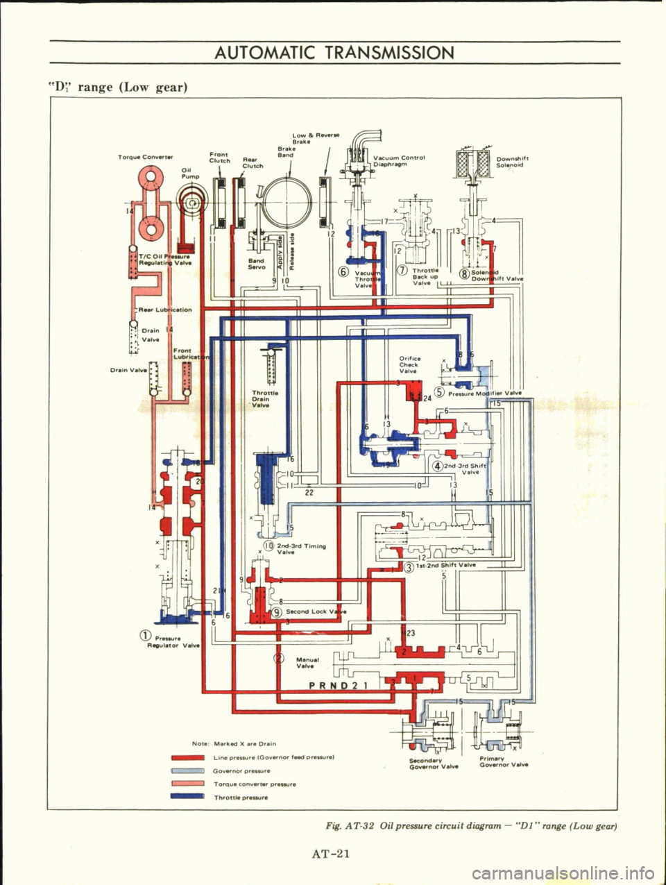
Fig
A
T
32
Oil
pressure
circuit
diagram
DJ
range
Low
gear
AT
21
Page 37 of 513

AUTOMATIC
TRANSMISSION
REMOVAL
AND
INSTAllATION
TRANSMISSION
ASSEMBLY
Removal
Installation
TRANSMISSION
ASSEMBLY
When
dismounting
the
automatic
transmission
from
a
vehicle
pay
at
tention
to
the
following
points
1
Before
dismounting
the
trans
mission
rigidly
inspect
it
by
aid
of
the
Troubleshooting
Chart
and
dis
mount
it
only
when
considered
to
be
necessary
2
Dismount
the
transmission
with
utmost
care
and
when
mounting
observe
the
tightening
torque
indi
cated
on
another
table
not
to
exert
excessive
force
Removal
In
dismounting
automatic
transmis
sion
from
vehicle
proceed
as
follows
i
Disconnect
battery
ground
cable
from
terminal
2
Jack
up
car
and
support
its
weight
on
safety
stands
Recommend
a
hydraulic
hoist
or
open
pit
be
utilized
if
available
Make
sure
that
safety
is
insured
3
Remove
propeller
shaft
Note
Plug
up
the
opening
in
the
rear
extension
to
prevent
oil
from
flowing
out
4
Disconnect
front
exhaust
tube
5
Disconnect
selector
range
lever
from
manual
shaft
6
Disconnect
wire
connections
at
inhibitor
switch
CONTENTS
AT
33
AT
33
AT
33
TRANSMISSION
CONTROL
LINKAGE
Removal
and
installation
Adjustment
AT
35
AT
36
AT
36
7
Disconnect
vacuum
tube
from
vacuum
diaphragm
and
wire
connec
tions
at
downshift
solenoid
8
Disconnect
speedometer
cable
from
rear
extension
9
Disconnect
oil
charging
pipe
10
Support
engine
by
locating
a
jack
under
oil
pan
with
a
wooden
block
used
between
oil
pan
and
jack
Support
transmission
by
means
of
3
transmission
jack
11
Detach
converter
housing
dust
cover
Remove
bolts
securing
torque
converter
to
drive
plate
See
Figure
AT
47
AT265
Fig
AT
47
Removing
torque
converter
attaching
bolt
Note
Before
removing
torque
con
verter
scribe
match
marks
on
two
parts
so
that
they
may
be
replaced
in
their
original
posi
tions
at
assembly
12
Disconnect
engine
moun
t
and
hand
lever
bracket
by
removing
two
2
rear
engine
mount
securing
bolts
and
two
2
crossmember
mounting
bolts
13
Remove
starter
motor
14
Remove
bolts
securing
transmis
sion
to
engine
After
removing
these
AT
33
bolts
support
engine
and
transmission
with
jack
and
lower
the
jack
gradually
until
transmission
can
be
removed
and
take
out
transmission
under
the
car
Note
Plug
up
the
opening
such
as
oil
charging
pipe
rear
extension
etc
Installation
Installation
of
automatic
transmis
sion
on
vehicle
is
reverse
order
of
removal
However
observe
the
follow
ing
installation
notes
Drive
plate
mnout
Turn
crankshaft
one
full
turn
and
measure
drive
plate
mnou
t
with
indi
cating
finger
of
a
dial
gauge
rested
against
plate
See
Figure
AT48
Replace
drive
plate
if
in
excess
of
0
5
mm
0
020
in
Maximum
allowable
mnout
0
3
mm
0
012
in
A
T266
Fig
A
T
48
Measuring
drive
plate
runout
2
Installation
of
torque
converter
Line
up
notch
in
torque
converter
with
that
in
oil
pump
Be
extremely
careful
not
to
cause
undue
stresses
in
parts
in
installing
torque
converter
See
Figure
A
T
49
Page 41 of 513

AUTOMATIC
TRANSMISSIO
N
i
MAJOR
REPAIR
OPERATION
SERVICE
NOTICE
FOR
DISASSEMBLY
AND
ASSEMBLY
TORQUE
CONVERTER
Inspection
TRANSMISSION
Disassembly
Inspection
Assembly
SERVICE
NOTICE
FOR
DISASSEMBLY
AND
ASSEMBLY
I
It
is
desirable
that
the
repair
operations
are
carried
out
in
the
dust
proof
room
2
Due
to
the
differences
of
the
engine
capacities
the
specifications
of
component
parts
for
each
model
s
transmission
may
be
different
How
ever
they
do
have
common
adJust
ments
and
repair
as
well
as
cleaning
and
inspection
procedures
ou
tlined
hereinafter
3
During
the
repair
operations
refer
to
the
Service
Data
and
Specifi
cations
section
for
the
correct
parts
for
the
applicable
model
transmission
4
Before
removing
any
of
subas
semblies
thoroughly
clean
the
outside
of
the
transmission
to
preven
t
dirt
from
entering
the
mechanical
parts
5
Do
not
use
a
waste
rag
Use
a
nylon
waste
or
paper
waste
6
After
disassembling
wash
all
dis
assembled
parts
clean
and
examine
them
to
see
if
there
are
any
worn
damaged
or
defective
parts
and
how
they
are
affected
Refer
to
Service
Data
for
the
extent
of
damage
that
justifies
replacement
7
Packings
seals
and
similar
parts
once
disassembled
should
be
replaced
with
new
ones
as
a
rule
TORQUE
CONVERTER
CONTENTS
AT
37
AT
37
AT
37
AT
37
AT
37
AT
39
AT
39
COMPONENT
PARTS
F
rant
clutch
Rear
clutch
Low
reverse
brake
Servo
piston
Governor
Oil
pump
Planetary
carrier
Control
valve
The
torque
converter
is
a
welded
construction
and
can
not
be
disas
sembled
Inspection
I
Check
torque
converter
for
any
sign
of
damage
bending
oil
leak
or
deformation
If
necessary
replace
2
Remove
rust
from
pilots
and
bosses
completely
If
torque
converter
oil
is
fouled
or
contaminated
due
to
burnt
clutch
flush
the
torque
converter
as
follows
I
Drain
oil
in
torque
converter
2
Pour
none
Iead
gasoline
or
kero
sene
into
torque
converter
approxi
mately
0
5
liter
I
1
8
V
S
p
7
8
Imper
p
3
Blow
air
into
torque
converter
and
flush
and
drain
out
gasoline
4
Fill
torque
converter
oil
into
torque
converter
approximately
0
5
liter
I
i
8
I
pt
7
8
lmper
pt
5
Again
blow
air
into
torque
con
verter
and
drain
torque
converter
oil
TRANSMISSION
Disassembly
I
Drain
oil
from
the
end
of
rear
extension
Mount
transmission
on
Transmission
Case
Stand
ST07860000
or
ST07870000
Remove
oil
pan
See
Figure
AT
52
AT
37
T
AT
41
AT
41
AT
42
AT
43
AT
43
AT
44
AT
44
AT
45
AT
45
2
Remove
bolts
securing
converter
housing
to
transmission
case
Remove
torque
converter
3
Remove
speedometer
pinion
sleeve
boll
Withdraw
pinion
4
Turn
off
by
hand
downshift
sole
noid
and
vacuum
diaphragm
Do
not
leave
diaphragm
rod
at
this
stage
of
disassembly
Rod
is
assembled
in
top
of
vacuum
diaphragm
See
Figure
AT
53
ST07860000
AT118
Fig
AT
52
Remouing
oil
pan
Show
2
liter
engine
model
Fig
A
T
53
Downshift
solenoid
and
uacuum
diaphragm
Page 42 of 513
I
J
It
r
I
x
f
Fig
AT
54
Remouing
valve
body
tt
l
v
AT121
Fig
A
T
55
Loosening
band
en
a
Fig
AT
56
Removing
oil
pump
AT123
Fig
A
T
5
7
Removing
band
strut
Fig
A
T
SS
Removing
connecting
shell
CHASSIS
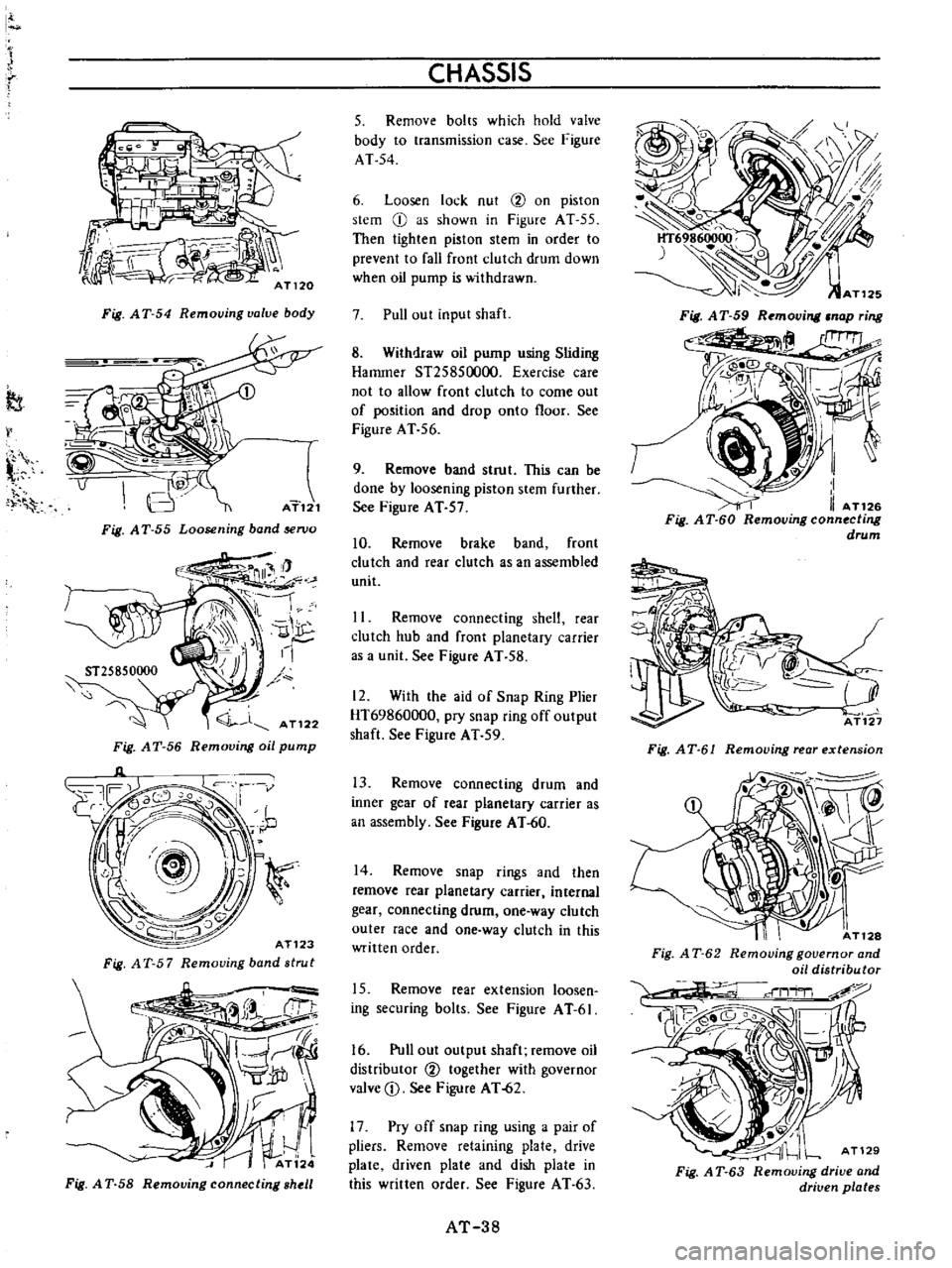
5
Remove
bolts
which
hold
valve
body
to
transmission
case
See
Figure
AT
54
6
Loosen
lock
nut
2
on
piston
stem
CI
as
shown
in
Figure
AT
55
Then
tighten
piston
stem
in
order
to
prevent
to
fall
front
clutch
drum
down
when
oil
pump
is
withdrawn
7
Pull
out
input
shaft
8
Withdraw
oil
pump
using
Sliding
Hammer
S125850000
Exercise
care
not
to
allow
front
clutch
to
come
out
of
position
and
drop
onto
floor
See
Figure
AT
56
9
Remove
band
strut
This
can
be
done
by
loosening
piston
stem
further
See
Figure
AT
57
10
Remove
brake
band
front
clutch
and
rear
clutch
as
an
assembled
unit
11
Remove
connecting
shelt
rear
clutch
hub
and
front
planetary
carrier
as
a
unit
See
Figure
AT
58
12
With
the
aid
of
Snap
Ring
Plier
HT69860000
pry
snap
ring
off
output
shaft
See
Figure
AT
59
13
Remove
connecting
drum
and
inner
gear
of
rear
planetary
carrier
as
an
assembly
See
Figure
AT
60
14
Remove
snap
rings
and
then
remove
rear
planetary
carrier
internal
gear
connecting
drum
one
way
clutch
outer
race
and
one
way
clutch
in
this
written
order
15
Remove
rear
extension
loosen
ing
securing
bolts
See
Figure
A
T
6I
16
Pull
out
output
shaft
remove
oil
distriburor
2
together
with
governor
valve
D
See
Figure
AT
62
17
Pry
off
snap
ring
using
a
pair
of
pliers
Remove
retaining
plate
drive
plate
driven
plate
and
dish
plate
in
this
written
order
See
Figure
AT
63
AT
38
Fig
AT
61
Removing
rear
extension
I
AT128
Fig
A
T
62
Removing
governor
and
oil
distributor
AT129
Fig
A
T
63
Removing
drive
and
driven
plates
Page 43 of 513
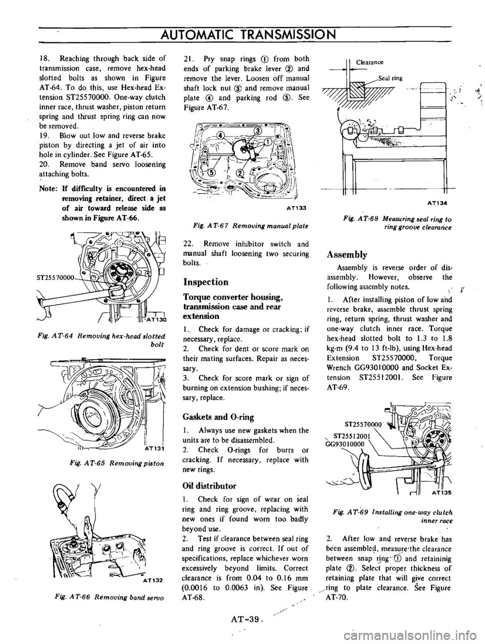
18
Reaching
through
back
side
of
transmission
case
remove
hex
head
slotted
bolts
as
shown
in
Figure
AT
64
To
do
this
use
Hex
head
Ex
tension
ST25570000
One
way
clutch
inner
race
thrust
washer
piston
return
spring
and
thrust
spring
ring
can
now
be
removed
19
Blowout
low
and
reverse
brake
piston
by
directing
a
jet
of
air
into
hole
in
cylinder
See
Figure
A
T
65
20
Remove
band
servo
loosening
attaching
bolts
Note
If
difficulty
is
encountered
in
removIng
retainer
direct
a
jet
of
air
toward
release
side
as
shown
in
Figure
AT
66
ST25570000
Fig
A
T
64
Removing
hex
head
lotted
bolt
Fig
A
T
65
Removing
pi
ton
r
AT132
Fig
A
T
66
Removing
band
seroo
AUTOMATIC
TRANSMISSION
21
Pry
snap
rings
CD
from
both
ends
of
parking
brake
lever
@
and
remove
the
lever
Loosen
off
manual
shaft
lock
nut
CID
and
remove
manual
plate
@
and
parking
rod
@
See
Figure
AT
67
Qd
i
f
W
II
4
i
n
n
r
1
K
j
e
0
H
o
i
j
j
I
j
l
m
r
JlII
2
U
r
K
F
J
r
0
f
1
r
AT133
Fig
A
T
67
Removing
manual
plate
22
Remove
inhibitor
switch
and
manual
shaft
loosening
two
securing
bolts
Inspection
Torque
converter
housing
transmission
case
and
rear
extension
1
Check
for
damage
or
cracking
if
necessary
replace
2
Check
for
dent
or
score
mark
on
their
mating
surfaces
Repair
as
neees
sary
3
Check
for
score
mark
or
sign
of
burning
on
extension
bushing
if
neces
sary
replace
Gaskets
and
O
ring
1
Always
use
new
gaskets
when
the
units
are
to
be
disassembled
2
Check
O
rings
for
burrs
or
cracking
If
necessary
replace
with
new
rings
Oil
distributor
I
Check
for
sign
of
wear
on
seal
ring
and
ring
groove
replacing
with
new
ones
if
found
worn
too
badly
beyond
use
2
Test
if
clearance
between
seal
ring
and
ring
groove
is
correct
If
out
of
specifications
replace
whichever
worn
excessively
beyond
limits
Correct
clearance
is
from
0
04
to
0
16
mm
0
0016
to
0
0063
in
See
Figure
AT
68
AT
39
Clearance
Seal
ring
F
1
I
i
h
AT134
Fig
A
T
68
Measuring
seal
ring
to
ring
groove
clearance
Assembly
Assembly
is
reverse
order
of
dis
assembly
However
observe
the
following
assembly
notes
1
After
installing
piston
of
low
and
reverse
brake
assemble
thrust
spring
ring
return
spring
thrust
washer
and
one
way
clutch
inner
race
Torque
hex
head
slotted
bolt
to
1
3
to
1
8
kg
m
94
to
13
ft
Ib
using
Hex
head
Extension
ST25570000
Torque
Wrench
GG930
1
0000
and
Socket
Ex
tension
ST25512001
See
Figure
AT
69
i
ST25570000
ST255
1
2001
GG93010000
0
rr
l
f
r
Fig
A
T
69
Installing
one
way
clutch
inner
race
2
After
low
and
reverse
brake
has
been
assemble
measure
the
clearance
between
snap
r
ng
cD
and
retaininig
plate
@
Select
proper
thickness
of
retaining
plate
that
will
gi
ve
correct
ring
to
plate
clearance
See
Figure
AT
70
Page 44 of 513
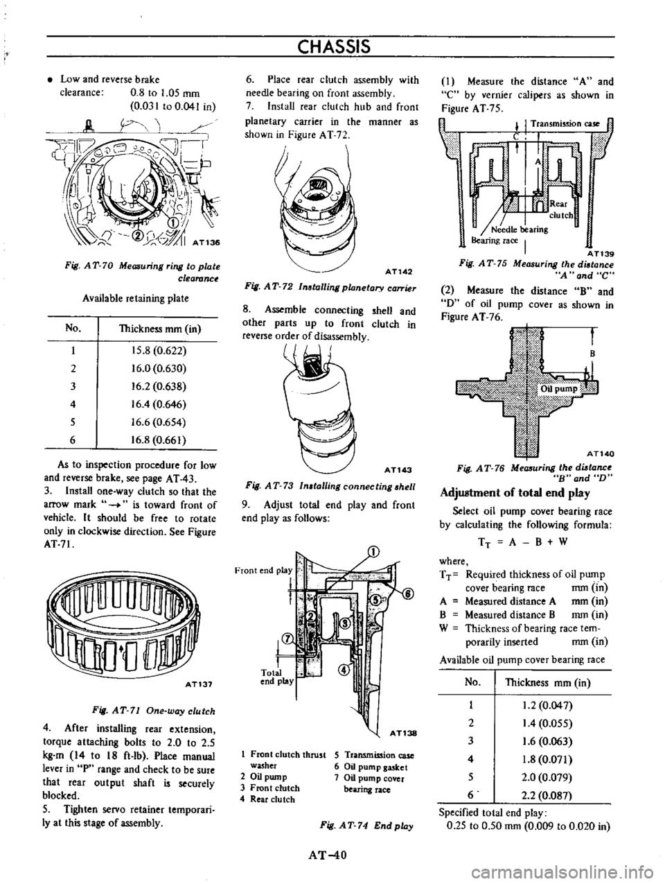
Low
and
reverse
brake
clearance
0
8
to
1
05
mm
0
031
to
0
041
in
Fig
AT
70
Measuring
ring
to
plate
clearanc
Available
retaining
plate
No
Thickness
mm
in
I
15
8
0
622
2
16
0
0
630
3
16
2
0
638
4
16
4
0
646
5
16
6
0
654
6
16
8
0
661
As
to
inspection
procedure
for
low
and
reverse
brake
see
page
AT
43
3
Install
one
way
clutch
so
that
the
arrow
mark
is
toward
front
of
vehicle
It
should
be
free
to
rotate
only
in
clockwise
direction
See
Figure
AT71
AT131
Fig
AT
71
One
way
clutch
4
After
installing
rear
extension
torque
attaching
bolts
to
2
0
to
2
5
kg
m
14
to
18
ft
lb
Place
manual
lever
in
P
range
and
check
to
be
sure
that
rear
output
shaft
is
securely
blocked
5
Tighten
servo
retainer
temporari
Iy
at
this
stage
of
assembly
CHASSIS
6
Place
rear
clutch
assembly
with
needle
bearing
on
front
assembly
7
Install
rear
clutch
hub
and
front
planetary
carrier
in
the
manner
as
shown
in
Figure
AT
72
AT142
Fig
AT
72
Installing
planetary
carrier
8
Assemble
connecting
shell
and
other
parts
up
to
front
clutch
in
reve
e
order
of
disassembly
ATl43
Fig
AT
73
In
talling
connecting
hell
9
Adjust
total
end
play
and
front
end
playas
follows
L
@
8
S
I
fT
15
l
r
1
Front
clutch
thrust
washer
2
Oil
pump
3
Front
clutch
4
Rear
du
tch
S
Transmission
case
6
Oil
pump
gasket
7
Oil
pump
cover
bearing
race
Fig
AT
74
Endplay
AT
40
I
Measure
the
distance
A
and
e
by
vernier
calipers
as
shown
in
Figure
AT
75
fl
l
I
Transmission
case
1l
Lf
ar
n
h
AT139
Fig
AT
75
Measuring
the
diltance
A
and
C
2
Measure
the
distance
B
and
D
of
oil
pump
COVer
as
shown
in
Figure
AT
76
B
AT140
Fig
AT
76
MeaJIuring
the
diltanc
B
and
D
Adjustment
of
total
end
play
Select
oil
pump
cover
bearing
race
by
calculating
the
following
formula
TT
A
B
W
where
TT
Required
thickness
of
oil
pump
cover
bearing
race
mm
in
A
Measured
distance
A
mm
in
B
Measured
distance
B
mm
in
W
Thickness
of
bearing
race
tem
porarily
inserted
mm
in
Available
oil
pump
cover
bearing
race
No
Thickness
mm
in
I
1
2
0
04
7
2
I
4
0
055
3
1
6
0
063
4
1
8
0
071
5
2
0
0
079
6
2
2
0
087
Specified
total
end
play
0
25
to
0
50
mm
0
009
to
0
020
in
Page 45 of 513
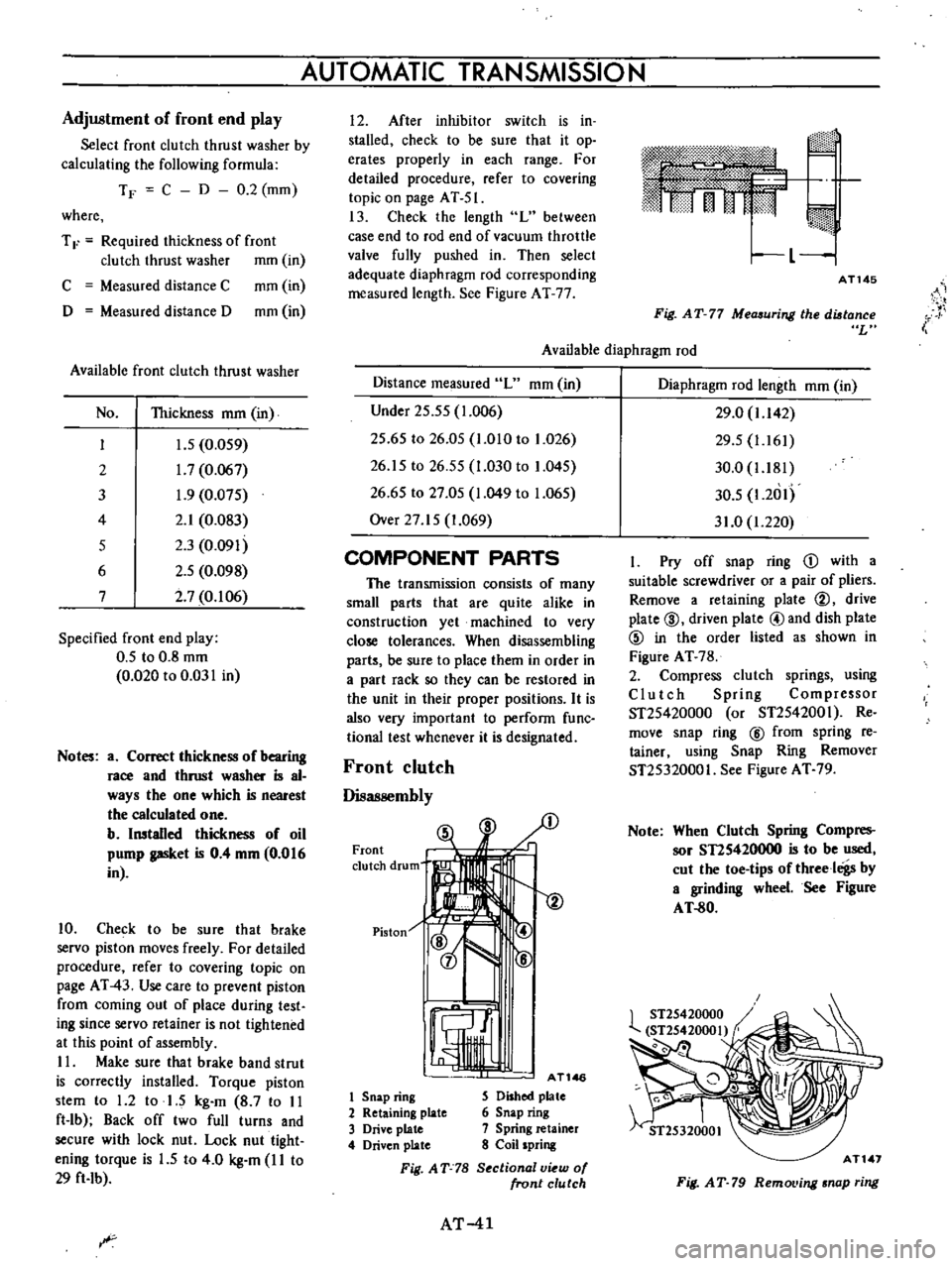
Adjustment
of
front
end
play
Select
front
clutch
thrust
washer
by
calculating
the
following
formula
TF
C
D
0
2
mm
where
T
F
Required
thickness
of
front
clutch
thrust
washer
mm
in
C
Measured
distance
C
mm
in
D
Measured
distance
D
mm
in
Available
front
clutch
thrust
washer
No
Thickness
mm
in
I
J
5
0
059
2
1
7
0
067
3
1
9
0
075
4
2
1
0
083
5
2
3
0
091
6
2
5
0
098
7
2
7
0
106
Specified
front
end
play
0
5
to
0
8
mm
0
020
to
0
031
in
Notes
a
Correct
thickness
of
bearing
race
and
thrust
washer
is
al
ways
the
one
which
is
nearest
the
calculated
one
b
Installed
thickness
of
oil
pump
gasket
is
0
4
mm
0
016
in
10
Check
to
be
sure
that
brake
servo
piston
moves
freely
For
detailed
procedure
refer
to
covering
topic
on
page
AT
43
Use
care
to
prevent
piston
from
coming
out
of
place
during
test
ing
since
servo
retainer
is
not
tightened
at
this
point
of
assembly
II
Make
sure
that
brake
band
strut
is
correctly
installed
Torque
piston
stem
to
1
2
to
1
5
kg
m
8
7
to
II
ft
lb
Back
off
two
full
turns
and
secure
with
lock
nut
Lock
nut
tight
ening
torque
is
1
5
to
4
0
kg
m
I
I
to
29
ft
Ib
AUTOMATIC
TRANSMISSION
I
2
After
inhibitor
switch
is
in
stalled
check
to
be
sure
that
it
op
erates
properly
in
each
range
For
detailed
procedure
refer
to
covering
topic
on
page
AT
51
13
Check
the
length
L
between
case
end
to
rod
end
of
vacuum
throttle
valve
fully
pushed
in
Then
select
adequate
diaphragm
rod
corresponding
measured
length
See
Figure
AT
77
m
rj
I
L
1
AT145
i
Fig
AT
77
Measuring
the
distance
L
Available
diaphragm
rod
Distance
measured
L
mm
in
Under
25
55
1
006
25
65
to
26
05
1
010
to
1
026
26
15
to
26
55
1
030
to
1
045
26
65
to
27
05
1
049
to
1
065
Over
27
15
1
069
COMPONENT
PARTS
The
transmission
consists
of
many
small
parts
that
are
quite
alike
in
construction
yet
machined
to
very
close
tolerances
When
disassembling
parts
be
sure
to
place
them
in
order
in
a
part
rack
so
they
can
be
restored
in
the
unit
in
their
proper
positions
It
is
also
very
important
to
perform
func
tional
test
whenever
it
is
designated
Front
clutch
Disassembly
Front
clutch
drum
Piston
1
AT146
1
Snap
ring
S
Dished
plate
2
Retaining
plate
6
Snap
ring
3
Drive
plate
7
Spring
retainer
4
Driven
plate
8
Coil
spring
Fig
AT
78
S
ctional
v
w
of
front
clutch
AT
41
Diaphragm
rod
length
mm
in
29
0
1
142
29
5
1
161
30
0
1
181
30
5
1
2
1I
31
0
1
220
I
Pry
off
snap
ring
D
with
a
suitable
screwdriver
or
a
pair
of
pliers
Remove
a
retaining
plate
@
drive
plate
@
driven
plate
@and
dish
plate
@
in
the
order
listed
as
shown
in
Figure
AT
78
2
Compress
clutch
springs
using
Clutch
Spring
Compressor
ST25420000
or
ST2542001
Re
move
snap
ring
@
from
spring
re
tainer
using
Snap
Ring
Remover
ST25320001
See
Figure
AT
79
Note
When
Clutch
Spring
Compres
sor
STIS420000
is
to
be
used
cut
the
toe
tips
of
threeloigs
by
a
grinding
wheel
See
Figure
AT
80
AT
1
Fig
AT
79
RemoL
ing
snap
ring
Page 47 of 513

3
Blowout
piston
by
directing
a
jet
of
air
into
hole
in
clutch
drum
See
Figure
AT
S
7
AT155
Fig
AT
87
Blowing
out
piston
Inspection
Refer
to
covering
topic
under
Front
Clutch
Assembly
Assembly
is
reverse
order
of
disas
sembly
Dip
all
parts
in
clean
auto
malic
transmission
fluid
before
as
sembling
Note
that
the
number
of
drive
and
driven
plates
varies
with
types
of
vehicles
For
details
refer
to
Service
Data
Specifications
I
After
rear
clutch
is
assembled
check
to
be
sure
that
clearance
be
tween
snap
ring
CD
and
retaining
plate
CV
is
held
within
prescribed
tolerances
See
Figure
A
T
S8
Specified
clearance
1
0
to
1
5
mm
0
039
to
0
059
in
AT1S6
Fig
A
T
88
Measuring
ring
to
plate
clearance
2
Testing
rear
clutch
Install
rear
clutch
on
oil
pump
cover
Blow
air
under
pressure
into
oil
hole
to
listen
for
definite
clutch
opera
tion
as
shown
in
Figure
AT
S9
AUTOMATIC
TRANSMISSION
AT157
Fig
AT
89
Testing
rear
clutch
Low
reverse
brake
Disassembly
I
Follow
steps
as
per
instructed
on
page
AT
38
2
Blowout
piston
by
directing
a
jet
of
air
into
oil
hole
in
clutch
piston
Inspection
I
Check
drive
plate
facing
for
wear
or
damage
if
necessary
replace
Refer
to
Service
Data
Specifications
for
limits
2
Test
if
piston
return
spring
is
not
weakened
Discard
if
weakened
too
badly
beyond
use
3
Replace
any
defective
parts
with
new
ones
Assembly
1
After
low
reverse
piston
is
installed
assemble
thrust
spring
ring
return
spring
thrust
washer
and
one
way
clutch
inner
race
With
the
aid
of
Hex
head
Extension
ST25570000
tighten
hex
head
slotted
bolt
1
3
to
1
8
kg
m
9
4
to
13
ft
Ib
2
Enter
dished
plate
driven
plate
drive
plate
and
retaining
plate
into
transmission
case
in
this
written
order
Install
snap
ring
to
secure
the
instal
lation
Note
The
number
of
drive
and
driven
plates
varies
with
types
of
vehi
cles
For
detailed
information
refer
to
Service
Data
Specifi
cations
AT
43
3
Without
disturbing
the
above
setting
check
to
be
sure
that
clearance
between
snap
ring
and
retaining
plate
is
held
within
specified
limits
If
nec
essary
try
with
other
plates
having
different
thickness
until
correct
clear
ance
is
obtained
Specified
clearance
O
SO
to
1
05
mm
0
031
to
0
041
in
4
Blow
under
pressure
air
into
oil
hole
in
low
reverse
brake
to
listen
for
definite
brake
operation
as
shown
in
Figure
AT
90
0j
L
J
1
1
I
1
I
Y
1
If
lY
v
A
we
1
a
II
I
7
r
AT158
Fig
AT
90
Testing
low
reverse
brake
Servo
piston
Disassembly
1
Blowout
piston
by
directing
a
jet
of
air
into
hole
in
release
side
of
piston
2
Remove
servo
piston
return
spring
Inspection
Check
piston
for
wear
damage
or
any
other
defects
which
might
inter
fere
with
proper
brake
operation
AT159
Fig
A
T
91
Removing
piston