1973 DATSUN B110 service
[x] Cancel search: servicePage 3 of 513

A
e
@
wWD@
mQD
1
p
DATSUN
1200
MODEL
B
11
0
SERIES
l
NISSAN
I
4
l
l
f
t
NI
SSAN
MOTOR
CO
LTD
TO
Yi
lIAPAN
SECTION
AT
AUTOMATIC
TRANSMISSION
DESCRIPTION
HYDRAULIC
CONTROL
SYSTEM
REMOVAL
AND
INSTALLATION
MAJOR
REPAIR
OPERATION
TROUBLE
DIAGNOSES
AND
ADJUSTMENT
SERVicE1
DATA
AND
SPECIFICATIONS
t
i
fr
lr
lo
i
1
4
1
p
i
AT
2
AT
4
AT
33
AT
31
AT
49
Al
60
1
r
1
i
J
Page 4 of 513

The
model
3N71
B
automatic
trans
mission
is
a
fully
automatic
unit
con
sisting
primarily
of
element
hydrau
lic
torque
converter
and
two
planetary
gear
sets
Two
multiple
disc
clutches
a
muItiple
disc
brake
a
band
brake
and
a
one
way
sprag
clutch
provide
the
friction
elements
required
to
obtain
the
desired
function
of
the
two
plane
tary
gear
sets
The
two
planetary
gear
sets
give
three
forward
ratios
and
one
reverse
Changing
of
the
gear
ratios
is
fully
automatic
in
relation
to
vehicle
speed
and
engine
torque
input
Vehicle
speed
and
engine
manifold
vacuum
signals
are
constantly
fed
to
the
transmission
to
provide
the
proper
gear
ratio
for
maximum
efficieq
cy
and
performance
at
all
thrqttIe
openings
The
iMiij
l
3N7I
B
has
six
selector
position
f
P
R
N
D
2
1
k
Park
position
positively
locks
the
c
ut
put
shaft
to
the
transmission
case
RY
means
of
a
locking
pawl
to
prev
nt
the
vehicle
from
rolling
either
direction
This
position
should
be
selected
when
ever
the
driver
leaves
the
vehicle
The
engine
may
be
started
in
Park
pQlition
OR
Reverse
range
enables
the
vehicle
to
be
operated
in
a
reverse
direction
N
Neutral
posItion
enables
the
engine
to
be
started
and
run
without
driving
the
vehicle
CHASSIS
DESCRIPTION
D
Drive
range
is
used
for
all
normal
driving
conditions
Drive
range
has
three
gear
ratios
frum
the
starting
ratio
to
direct
drive
2
2
range
provides
performance
for
driving
on
slippery
surfaces
2
range
can
also
be
used
for
engine
braking
2
range
can
be
selected
at
any
vehicle
speed
and
prevents
the
trans
mission
from
shifting
out
of
second
gear
I
range
can
be
selected
at
any
vehicle
speed
and
the
transmission
will
shift
to
second
gear
and
remain
in
second
until
vehide
speed
is
reduced
to
approximately
40
to
50
kmfh
25
to
31
MPH
I
range
position
prevents
the
transmission
from
shifting
out
of
low
gear
This
is
particularly
beneficial
for
maintaining
maximum
engine
braking
when
continuous
low
gear
operation
is
desirable
The
torque
converter
assembly
is
of
welded
construction
and
can
not
be
disassemble
for
service
Fluid
recommendation
Use
having
only
in
mission
automatic
transmission
fluid
DEXRON
identifications
the
3N7I
B
automatic
trans
AT
2
IA
e
l
csr
4o
J
r
s
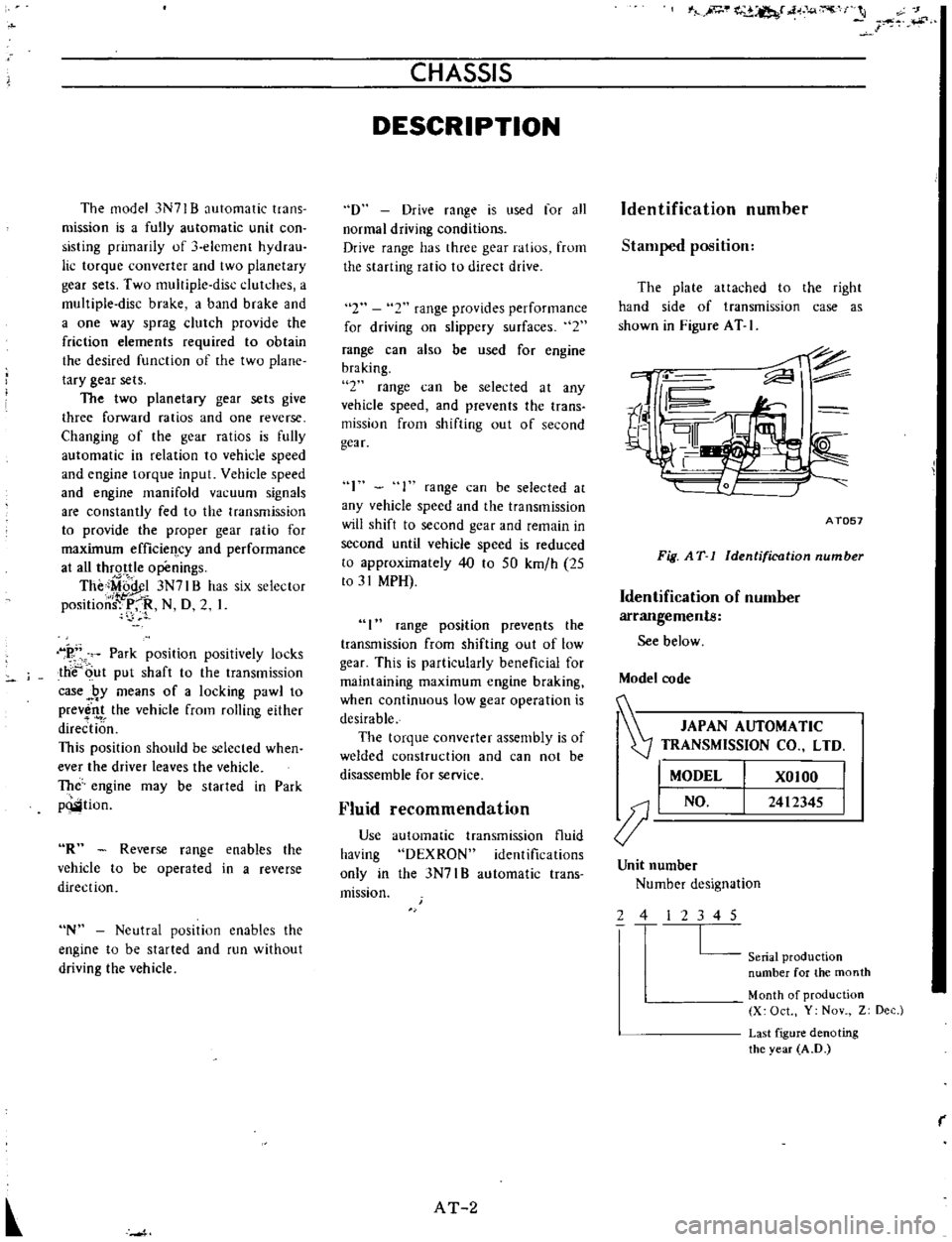
Identification
number
Stamped
position
The
plate
attached
to
the
right
hand
side
of
transmission
case
as
shown
in
Figure
AT
I
ii
II
r
4
1
r
I
to
i
AT057
Fig
AT
1
Identification
number
Identification
of
number
arrangements
See
below
Model
code
JAPAN
AUTOMATIC
Z
TRANSMISSION
CO
LTD
I
MODEL
XOIOO
J
I
NO
2412345
Unit
number
Number
designation
2
4
2
3
4
5
L
Seriat
production
number
for
the
month
Month
of
production
X
Oct
Y
Nov
Z
Dec
Last
figure
denoting
the
year
A
D
r
Page 9 of 513

IN
This
quality
product
has
been
packaged
by
hand
If
you
have
any
difficulty
please
mention
my
number
in
your
correspondence
Thank
you
2655
HURST
PERFORMANCE
INC
50
WEST
STREET
ROAD
WARMINSTER
PA
18974
ATTENTION
CUSTOMER
SERVICE
j
PLACE
STAMP
HERE
Page 10 of 513

LIMITED
WARRANTY
Your
Hurst
product
warranted
per
table
below
Irom
dale
01
purchase
against
defects
materinl
and
workmanship
Dur
ing
this
period
luch
defects
will
be
repoired
the
product
will
be
chllnQl
d
at
Huut
option
without
charge
This
war
onty
does
damiilge
used
bv
milu
lI
alteration
negligence
ALL
IMPLIED
WARRANTIES
INCLUDING
BUT
NOT
LIMITED
TO
WARRANTIES
OF
FITNESS
AND
MER
CHANTABllITV
ARE
LIMITED
IN
DURATION
TO
A
PE
RIOO
ENDING
WITH
THE
PERIOD
OF
THE
CORRESPOND
ING
EXPRESS
LIMITED
WARRANTY
AS
SET
FORTH
BE
LOW
UNDER
NO
CIRCUMSTANCES
WILL
HURST
BE
RE
SPONSI8LE
FOR
INCIDENTAL
OR
CONseQUENTIAL
DAMAGES
ARISING
FADM
OR
IN
CONNECTION
WITH
THE
INSTALLATION
OR
USE
OF
ANY
HURST
PRODUCT
Some
tates
do
not
allow
limitations
on
how
long
implied
warranty
lasts
do
not
allow
for
tha
Axclusion
limitation
of
incidental
nnlequantial
damages
the
above
limitations
may
not
apply
to
you
This
Warranty
givlIs
you
specific
legal
righta
and
you
may
also
have
other
rights
which
Vpry
from
state
to
state
Return
of
the
Product
Registration
Card
nOt
nndition
precedent
Warranty
nvAraga
and
performance
HURST
WARRANTY
PERIODS
from
cJ
ffI
of
purch
lt
I
Shift
rs
Air
Shocks
12monttlt
12
OOOmil
or
12month1
whch
ver
lim
gOd
vl
12montl1s
12montl1s
12montl1s
Aoeellories
Tr
Rlmission
Oil
Coolers
Autom
tic
Tr
umitsion
P
rh
Scl1i
f
rPloductt
J
c
udinll
producrr
u
d
fOT
rw
ingl
Bring
the
product
or
nd
it
pOttage
preplidf
Hurst
Performance
Inc
or
IIuthorized
doaler
If
you
end
the
product
pleas
write
letter
IIxplaining
the
01
your
difficulty
HURST
PERFORMANCE
INC
50
West
Street
Road
Warminnl
r
PennsylvlInlll18974
In
tha
ellenl
you
have
any
questions
rning
IInd
of
the
product
rning
pleese
write
Customer
Satisfaction
Depertment
lit
above
addreu
How
To
Get
Quick
Service
1
Peck
your
Hunt
product
r
nrefully
good
IriOn
with
plenty
of
newspape
s
u
celsior
padding
all
mund
it
and
till
lIly
Oamllge
transit
not
nv
red
by
the
warranty
2
Carefully
prinl
the
lrton
thlll
name
Ind
Iddrllu
01
Hurl
above
Don
t
forget
your
return
addreu
3
Put
I
tter
showing
desired
n
lIlope
addressed
HUrl
above
In
your
lettllr
plellSe
be
to
give
full
formation
such
date
and
place
of
purchase
your
full
name
IInd
address
and
the
reptllrS
d
sired
4
PASTE
ENVELOPE
TO
PACKAGE
S
Put
First
CIBst
stamp
nvelope
IInd
Parcel
Pall
stamps
package
then
mail
The
Post
Office
will
tell
yOU
the
proper
amount
of
postage
and
against
Iou
the
mDils
z
it
l
l
III
0
1168
a
o
o
i
g
I
o
0
DO
o
0
I
t
i
lL
5
I
0
q
II
1
I
if
18
0
l
q
t
tJ
w
j
b
00000
i
I
a
1
I
S
z
I
i
o
i
i
I
c
q
3
10
w
ol
8
q
1
5
lj
I
u
i
i
i
@
z
i
i
tii
I
f
8
ts
I
5
i
a
s
fl
00000000000000
C
a
0
u
Z
o
a
ti
a
w
a
u
J
C
o
a
lIt
c
l
l
c
l
J
Ci
I
J
I
I
a
1111
i
Z
iRI
1
Ii
iD
i
8
1
I
1I
o
0
1
o
011
Dl
DI
oj
o
Page 38 of 513

Fig
A
T
49
Torque
converter
aligning
cut
3
When
connecting
torque
con
verter
to
transmission
measure
dis
tance
A
to
be
certain
that
they
are
correctly
assembled
See
Figure
AT
50
Distance
A
More
than
16
5
IllIll
0
650
in
A
AT117
Fig
A
T
50
Installing
torque
converter
CHASSIS
4
Bolt
converter
to
drive
plate
Tightening
torque
0
8
to
1
0
kg
Ill
5
8
to
7
2
ft
Ib
Note
Align
chalk
marks
painted
a
cross
both
parts
during
disas
sembling
processes
5
After
converter
is
installed
rotate
crankshaft
several
turns
and
check
to
be
sure
that
transmission
rotates
freely
without
binding
6
Pour
recommended
automatic
transmission
fluid
up
to
correct
level
through
oil
charge
pipe
7
Connect
manual
lever
to
shift
rod
Operation
should
be
carried
out
with
manual
and
selector
levers
in
N
8
Connect
inhibitor
switch
wires
Notes
a
Refer
to
covering
topic
under
Checking
and
adjusting
inhibitor
switch
on
page
AT
51
b
Inspect
and
adjust
switch
as
above
whenever
it
has
to
be
removed
for
service
9
Check
inhibitor
switch
for
op
eration
AT
34
Starter
should
be
brought
into
op
eration
only
when
selector
lever
is
in
P
and
N
positions
it
should
not
be
started
when
lever
is
in
D
2
1
and
R
positions
Back
up
lamp
should
also
light
when
selector
lever
is
placed
in
R
position
10
Check
level
of
oil
in
transmis
sion
For
detailed
procedure
see
page
AT
49
II
Move
selector
lever
through
all
positions
to
be
sure
that
transmission
operates
correctly
With
hand
brake
applied
rotate
engine
at
idling
Without
disturbing
the
above
setting
move
selector
lever
through
N
to
D
to
2
to
I
and
to
R
A
slight
shock
should
be
felt
by
hand
gripping
selector
each
time
transmission
is
shifted
Note
See
page
AT
50
for
checking
enigne
idling
12
Check
to
be
sure
that
line
pres
sure
is
correct
To
do
this
refer
to
relative
topic
under
Testing
line
pres
sure
on
page
AT
53
13
Perform
stall
test
as
per
the
instructions
on
page
AT
51
Page 41 of 513

AUTOMATIC
TRANSMISSIO
N
i
MAJOR
REPAIR
OPERATION
SERVICE
NOTICE
FOR
DISASSEMBLY
AND
ASSEMBLY
TORQUE
CONVERTER
Inspection
TRANSMISSION
Disassembly
Inspection
Assembly
SERVICE
NOTICE
FOR
DISASSEMBLY
AND
ASSEMBLY
I
It
is
desirable
that
the
repair
operations
are
carried
out
in
the
dust
proof
room
2
Due
to
the
differences
of
the
engine
capacities
the
specifications
of
component
parts
for
each
model
s
transmission
may
be
different
How
ever
they
do
have
common
adJust
ments
and
repair
as
well
as
cleaning
and
inspection
procedures
ou
tlined
hereinafter
3
During
the
repair
operations
refer
to
the
Service
Data
and
Specifi
cations
section
for
the
correct
parts
for
the
applicable
model
transmission
4
Before
removing
any
of
subas
semblies
thoroughly
clean
the
outside
of
the
transmission
to
preven
t
dirt
from
entering
the
mechanical
parts
5
Do
not
use
a
waste
rag
Use
a
nylon
waste
or
paper
waste
6
After
disassembling
wash
all
dis
assembled
parts
clean
and
examine
them
to
see
if
there
are
any
worn
damaged
or
defective
parts
and
how
they
are
affected
Refer
to
Service
Data
for
the
extent
of
damage
that
justifies
replacement
7
Packings
seals
and
similar
parts
once
disassembled
should
be
replaced
with
new
ones
as
a
rule
TORQUE
CONVERTER
CONTENTS
AT
37
AT
37
AT
37
AT
37
AT
37
AT
39
AT
39
COMPONENT
PARTS
F
rant
clutch
Rear
clutch
Low
reverse
brake
Servo
piston
Governor
Oil
pump
Planetary
carrier
Control
valve
The
torque
converter
is
a
welded
construction
and
can
not
be
disas
sembled
Inspection
I
Check
torque
converter
for
any
sign
of
damage
bending
oil
leak
or
deformation
If
necessary
replace
2
Remove
rust
from
pilots
and
bosses
completely
If
torque
converter
oil
is
fouled
or
contaminated
due
to
burnt
clutch
flush
the
torque
converter
as
follows
I
Drain
oil
in
torque
converter
2
Pour
none
Iead
gasoline
or
kero
sene
into
torque
converter
approxi
mately
0
5
liter
I
1
8
V
S
p
7
8
Imper
p
3
Blow
air
into
torque
converter
and
flush
and
drain
out
gasoline
4
Fill
torque
converter
oil
into
torque
converter
approximately
0
5
liter
I
i
8
I
pt
7
8
lmper
pt
5
Again
blow
air
into
torque
con
verter
and
drain
torque
converter
oil
TRANSMISSION
Disassembly
I
Drain
oil
from
the
end
of
rear
extension
Mount
transmission
on
Transmission
Case
Stand
ST07860000
or
ST07870000
Remove
oil
pan
See
Figure
AT
52
AT
37
T
AT
41
AT
41
AT
42
AT
43
AT
43
AT
44
AT
44
AT
45
AT
45
2
Remove
bolts
securing
converter
housing
to
transmission
case
Remove
torque
converter
3
Remove
speedometer
pinion
sleeve
boll
Withdraw
pinion
4
Turn
off
by
hand
downshift
sole
noid
and
vacuum
diaphragm
Do
not
leave
diaphragm
rod
at
this
stage
of
disassembly
Rod
is
assembled
in
top
of
vacuum
diaphragm
See
Figure
AT
53
ST07860000
AT118
Fig
AT
52
Remouing
oil
pan
Show
2
liter
engine
model
Fig
A
T
53
Downshift
solenoid
and
uacuum
diaphragm
Page 46 of 513

L
J
i
C
E
Ee
1f
20mm
8
0
079
in
AT148
Cut
off
hatched
portion
Fig
A
T
80
Modifying
of
coil
spring
compres
or
3
Take
out
spring
retainer
j
and
spring@
See
Figure
AT
7
4
Blowout
piston
by
directing
a
iet
of
air
into
hole
in
clutch
drum
See
Figure
AT
I
Fig
AT
81
Blowing
out
pi3ton
Inspection
I
Check
for
sign
of
wear
or
damage
to
clutch
drive
plate
facing
If
found
worn
or
damaged
excessively
discard
See
Service
Data
for
limits
2
Check
for
wear
on
snap
ring
and
for
weakened
or
broken
coil
spring
If
necessary
replace
with
new
ones
Spring
retainer
should
also
be
in
spected
for
warpage
Assembly
I
Assembly
is
reverse
order
of
disas
sembly
Dip
aU
parts
in
clean
auto
matic
transmission
fluid
before
they
can
be
installed
2
Line
up
driven
plates
so
that
stripped
arcs
are
properly
aligned
pay
iog
particular
attention
to
the
location
of
oil
holes
in
clutch
drum
See
Figure
AT
82
Note
The
number
of
drive
and
driven
plates
varies
with
the
type
of
vehicles
For
detailed
informa
tion
also
see
Service
Data
Specifications
CHASSIS
AT150
Lubrication
hole
Fig
A
T
82
Inserting
clutch
plate
3
After
clutch
is
assembled
make
sure
that
clearance
between
snap
ring
CD
and
retaining
plate
@
is
held
within
specified
limits
If
necessary
try
with
other
plates
having
different
thickness
until
correct
clearance
is
obtained
See
Figure
AT
3
Specified
clearance
1
6
to
1
mm
0
063
to
0
071
in
Available
retaining
plate
No
Thickness
mm
in
I
10
6
0
417
2
10
0
425
3
11
0
0
433
4
11
2
0
441
5
II
4
0
449
6
11
6
0
457
AT151
Fig
A
T
83
MeOJluring
ring
to
plate
clearance
4
Testing
front
clutch
With
front
clutch
assembled
on
oil
pump
cover
direct
a
jet
of
air
into
hole
in
clutch
drum
See
Figure
AT
4
AT
42
Fig
A
T
84
Tesling
front
clutch
Rear
clutch
Disassembly
CD
ID
@
f
@
@
I
J
L
@
@
@
AT269
I
Rear
clutch
drum
6
Retaining
plate
2
Piston
7
Spring
retainer
3
Di
ed
plate
8
Drive
plate
4
Coil
spring
9
Driven
plate
5
Snap
ring
Fig
A
T
85
Sectional
view
of
Tear
clutch
I
Take
out
snap
ring
@
retaining
plate
@
drive
plate
l
driven
plate
@
and
dished
plate
j
Same
tech
nique
can
be
applied
as
in
disassem
bling
front
clutch
See
Figure
A
T
5
2
Remove
snap
ring
from
coil
spring
retainer
See
Figure
AT
6
ST25420000
ST2542000l
Ii
Removing
snap
ring
Page 47 of 513

3
Blowout
piston
by
directing
a
jet
of
air
into
hole
in
clutch
drum
See
Figure
AT
S
7
AT155
Fig
AT
87
Blowing
out
piston
Inspection
Refer
to
covering
topic
under
Front
Clutch
Assembly
Assembly
is
reverse
order
of
disas
sembly
Dip
all
parts
in
clean
auto
malic
transmission
fluid
before
as
sembling
Note
that
the
number
of
drive
and
driven
plates
varies
with
types
of
vehicles
For
details
refer
to
Service
Data
Specifications
I
After
rear
clutch
is
assembled
check
to
be
sure
that
clearance
be
tween
snap
ring
CD
and
retaining
plate
CV
is
held
within
prescribed
tolerances
See
Figure
A
T
S8
Specified
clearance
1
0
to
1
5
mm
0
039
to
0
059
in
AT1S6
Fig
A
T
88
Measuring
ring
to
plate
clearance
2
Testing
rear
clutch
Install
rear
clutch
on
oil
pump
cover
Blow
air
under
pressure
into
oil
hole
to
listen
for
definite
clutch
opera
tion
as
shown
in
Figure
AT
S9
AUTOMATIC
TRANSMISSION
AT157
Fig
AT
89
Testing
rear
clutch
Low
reverse
brake
Disassembly
I
Follow
steps
as
per
instructed
on
page
AT
38
2
Blowout
piston
by
directing
a
jet
of
air
into
oil
hole
in
clutch
piston
Inspection
I
Check
drive
plate
facing
for
wear
or
damage
if
necessary
replace
Refer
to
Service
Data
Specifications
for
limits
2
Test
if
piston
return
spring
is
not
weakened
Discard
if
weakened
too
badly
beyond
use
3
Replace
any
defective
parts
with
new
ones
Assembly
1
After
low
reverse
piston
is
installed
assemble
thrust
spring
ring
return
spring
thrust
washer
and
one
way
clutch
inner
race
With
the
aid
of
Hex
head
Extension
ST25570000
tighten
hex
head
slotted
bolt
1
3
to
1
8
kg
m
9
4
to
13
ft
Ib
2
Enter
dished
plate
driven
plate
drive
plate
and
retaining
plate
into
transmission
case
in
this
written
order
Install
snap
ring
to
secure
the
instal
lation
Note
The
number
of
drive
and
driven
plates
varies
with
types
of
vehi
cles
For
detailed
information
refer
to
Service
Data
Specifi
cations
AT
43
3
Without
disturbing
the
above
setting
check
to
be
sure
that
clearance
between
snap
ring
and
retaining
plate
is
held
within
specified
limits
If
nec
essary
try
with
other
plates
having
different
thickness
until
correct
clear
ance
is
obtained
Specified
clearance
O
SO
to
1
05
mm
0
031
to
0
041
in
4
Blow
under
pressure
air
into
oil
hole
in
low
reverse
brake
to
listen
for
definite
brake
operation
as
shown
in
Figure
AT
90
0j
L
J
1
1
I
1
I
Y
1
If
lY
v
A
we
1
a
II
I
7
r
AT158
Fig
AT
90
Testing
low
reverse
brake
Servo
piston
Disassembly
1
Blowout
piston
by
directing
a
jet
of
air
into
hole
in
release
side
of
piston
2
Remove
servo
piston
return
spring
Inspection
Check
piston
for
wear
damage
or
any
other
defects
which
might
inter
fere
with
proper
brake
operation
AT159
Fig
A
T
91
Removing
piston