1973 DATSUN B110 service
[x] Cancel search: servicePage 49 of 513
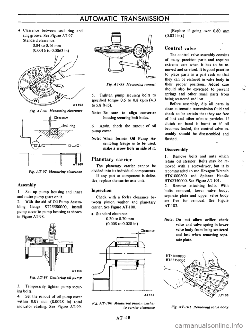
Clearance
between
seal
ring
and
ring
groove
See
Figure
AT
97
Standard
clearance
0
04toO
16mm
0
0016
to
0
0063
in
AT162
Fig
A
T
96
Measuring
clearance
I
earance
I
Seal
rIng
0d
t
AT185
II
Fig
AT
97
Measuring
clearance
Assembly
1
Set
up
pump
housing
and
inner
and
outer
pump
gears
on
it
2
With
the
aid
of
Oil
Pump
Assem
bling
Gauge
ST255800oo
install
pump
cover
to
pump
housing
as
shown
in
Figure
AT
98
lnnrr
i
rnl
l
AT166
Fig
A
T
98
Centering
oil
pump
3
Temporarily
tighten
pump
secur
ing
bolts
4
Set
the
runout
of
oil
pump
cover
within
0
07
mm
0
0028
in
total
indicator
reading
See
Figure
A
T
99
AUTOMATIC
TRANSMISSION
AT264
Fig
A
T
99
Measuring
run
out
5
Tighten
pump
securing
bolts
to
specified
torque
0
6
to
0
8
kg
m
4
3
to
5
8
ft
Ib
Note
Be
sure
to
align
converter
housing
securing
bolt
holes
6
Again
check
the
runout
of
oil
pump
cover
Note
When
former
Oil
Pump
As
sembling
Gauge
is
to
be
used
make
a
screw
hole
in
side
of
it
Planetary
carrier
The
planetary
carrier
cannot
be
divided
into
its
individual
components
If
any
part
or
component
is
defec
tive
replace
the
carrier
as
a
unit
Inpsection
Check
with
a
feeler
clearance
be
tween
pinion
washer
and
planetary
carrier
See
Figure
AT
100
Standard
clearance
0
20
to
0
70
mm
0
008
to
0
028
in
Clearance
I
LJ
b
II
I
AT161
Fig
AT
100
Mea
uring
pinion
washer
to
carrier
clearance
AT
45
Replace
if
going
over
0
80
mm
0
031
in
Control
valve
The
control
valve
assembly
consists
of
many
precision
parts
and
requires
extreme
care
when
it
has
to
be
re
moved
and
serviced
It
is
good
practice
to
place
parts
in
a
part
rack
so
that
they
can
be
restored
in
valve
body
in
their
proper
positions
Added
care
should
also
be
exercised
to
prevent
springs
and
other
small
parts
from
being
scattered
and
lost
Before
assembly
dip
all
parts
in
clean
automatic
transmission
nuid
and
check
to
be
certain
that
they
are
free
of
lint
and
other
minute
particles
If
clutch
or
band
is
burnt
or
if
oil
becomes
fouled
the
control
valve
as
sembly
should
be
disassembled
and
flushed
Disassembly
1
Remove
bolts
and
nuts
which
retain
oil
strainer
Bolts
may
be
re
moved
with
a
screwdriver
but
it
is
recommended
to
use
Hexagon
Wrench
HT61000800
and
Spinner
Handle
HT62350000
See
Figure
AT
10
I
2
Remove
attaching
bolts
With
bolts
removed
lower
valve
body
separate
plate
and
upper
valve
body
are
free
for
removal
See
Figure
AT
102
Note
Do
not
allow
orifice
check
valve
and
valve
spring
in
lower
valve
body
from
being
scattered
and
lost
when
removing
sepa
rate
plate
HT61000BOO
HT62350000
Fig
AT
101
Removing
valve
body
Page 64 of 513

CHASSIS
SERVICE
DATA
AND
SPECIFICATIONS
General
specifications
Torque
converter
Type
Stall
torque
ratio
Transmission
Type
Control
elements
Gear
ratio
Selector
positions
Oil
pump
Type
Number
of
pump
Oil
Capacity
Hydraulic
control
system
Lubrication
system
Cooling
system
Multiple
disc
clutch
Band
brake
Multiple
disc
brake
One
way
clutch
1st
lnd
3rd
Reverse
P
Park
R
Reverse
N
Neutral
D
Drive
1
lnd
lock
I
Lock
up
AT
60
Symmetrical3
element
I
stage
l
phase
torque
converter
coupling
2
0
I
3
speed
forward
and
one
speed
reverse
with
planetary
gear
train
1
I
I
I
2
458
1
458
1
000
2
182
The
transmission
is
placed
in
neutral
The
output
shaft
is
fixed
The
engine
can
be
started
Backward
running
The
transmission
is
in
neutral
The
engine
can
be
started
Up
or
downshifts
automatically
to
and
from
1st
lnd
and
top
Fixed
at
2nd
Fixed
at
low
or
downshifts
from
2nd
Internally
intermeslting
involute
gear
pump
Automatic
transmission
fluid
Dexron
type
5
5
liters
57
8
U
S
qts
47
8
Imp
qts
Approximately
1
7
liters
27
8
U
S
qts
2
3
8
Imp
qts
in
torque
converter
Controlled
by
detecting
the
negative
pressure
of
intake
manifold
and
the
revolution
speed
of
output
shaft
Forced
lubrication
by
an
oil
pwnp
Air
cooled
Page 68 of 513
PROPELLER
SHAFT
DIFFERENTIAL
CARRIER
PROPELLER
SHAFT
AND
UNIVERSAL
JOINT
CONTENTS
DESC
R
I
PTI
ON
REMOVAL
DISASSEMBL
Y
INSPECTION
ASSEMBL
Y
PD
PD
2
PD
2
PD
2
PD
2
SERVICE
DATA
AND
SPECIFICATIONS
TROUBLE
DIAGNOSES
AND
CORRECTIONS
PD
3
PD
3
j
j
lI
ID
1
Assembly
yoke
sleeve
2
As
mbly
journal
with
lever
3
Ring
snap
bearing
race
4
Assembly
race
bearing
5
Assembly
journal
with
bearing
6
Yoke
flange
7
Ring
snap
bearing
race
8
Assembly
race
bearing
9
Bolt
10
Washer
lock
11
Nut
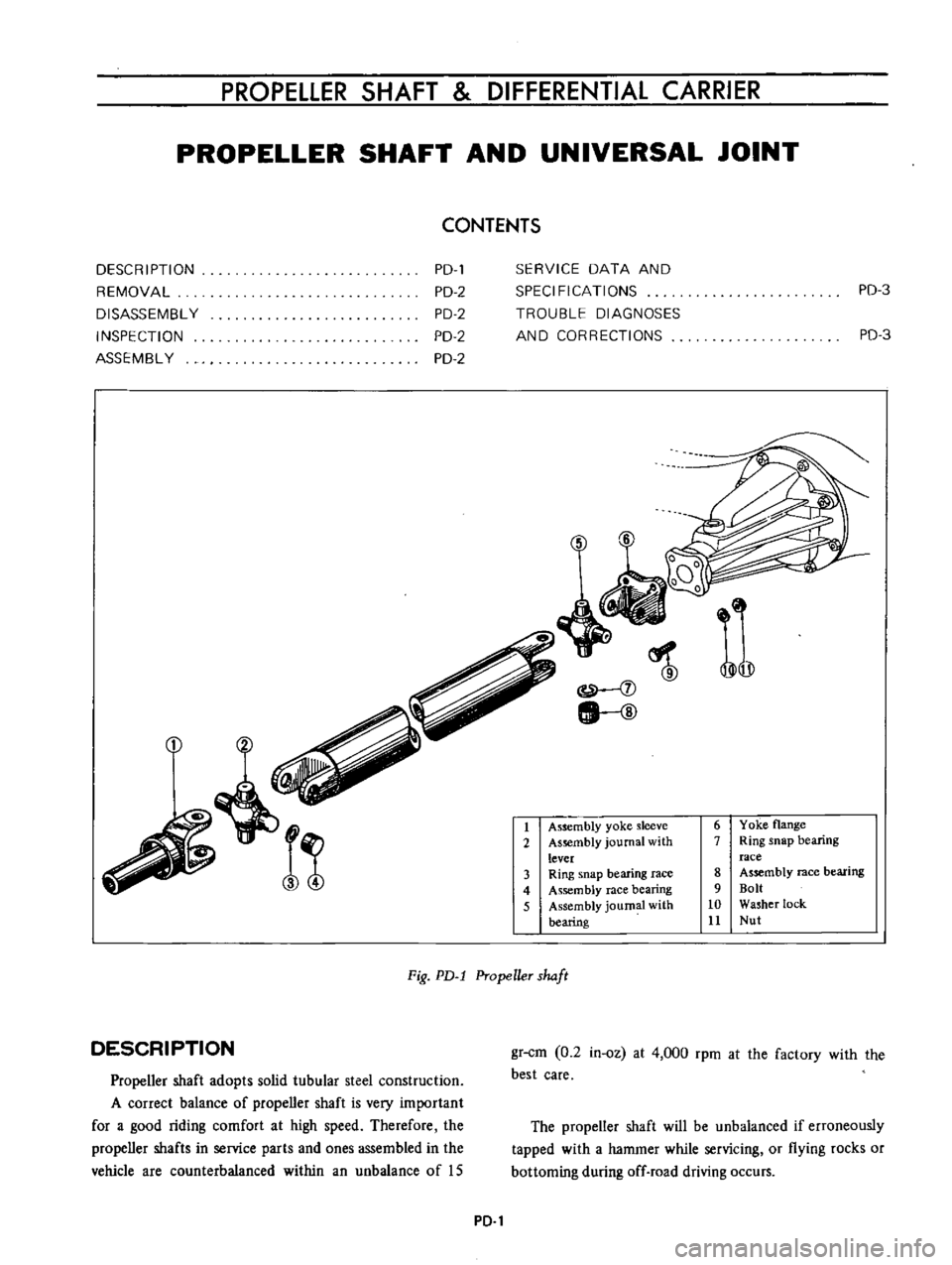
Fig
PD
l
Propeller
shaft
DESCRIPTION
Propeller
shaft
adopts
solid
tubular
steel
construction
A
correct
balance
of
propeller
shaft
is
very
important
for
a
good
riding
comfort
at
high
speed
Therefore
the
propeller
shafts
in
service
parts
and
ones
assembled
in
the
vehicle
are
counterbalanced
within
an
unbalance
of
IS
gr
cm
0
2
in
oz
at
4
000
rpm
at
the
factory
with
the
best
care
The
propeller
shaft
will
be
unbalanced
if
erroneously
tapped
with
a
hammer
while
servicing
or
flying
rocks
or
bottoming
during
off
road
driving
occurs
PD
1
Page 70 of 513
PROPELLER
SHAFT
DIFFERENTIAL
CARRIER
Insert
the
journal
into
the
yoke
flange
Tap
the
journal
bearing
into
the
yoke
flange
using
a
brass
drift
smaller
than
the
hole
in
the
yoke
Tap
the
other
bearing
into
the
opposite
end
of
the
yoke
flange
until
the
bearing
is
in
line
with
the
snap
ring
grooves
With
a
pair
of
pliers
install
the
snap
rings
on
both
ends
of
the
yoke
flange
Insert
the
flange
assembly
in
the
sleeve
yoke
Place
the
other
yoke
bearing
into
the
opposite
end
of
the
yoke
and
tap
this
bearing
into
the
yoke
until
the
bearing
is
in
line
with
the
snap
ring
grooves
Install
the
snap
rings
on
both
ends
of
the
yoke
When
all
parts
are
assembled
check
the
spider
and
surroundings
for
tightness
When
the
clearance
is
excessive
adjust
with
over
size
snap
rings
as
follows
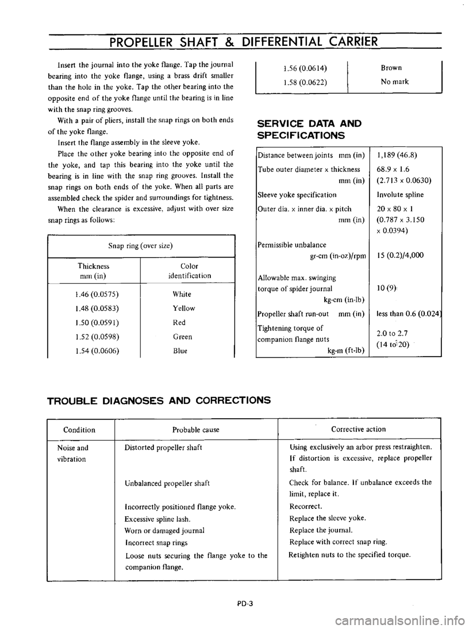
Snap
ring
over
size
Thickness
Color
mrn
in
identification
I
46
0
0575
White
I
48
0
0583
Yellow
1
50
0
0591
Red
1
52
0
0598
Green
1
54
0
0606
Blue
1
56
0
0614
1
58
0
0622
SERVICE
DATA
AND
SPECIFICATIONS
Distance
between
joints
mm
in
Tube
outer
diameter
x
thickness
mm
in
Sleeve
yoke
specification
Outer
dia
x
inner
dia
x
pitch
mm
in
Brown
No
mark
I
189
46
8
68
9
x
1
6
2
713
x
0
0630
Involute
spline
20
x
80
x
I
0
787
x
3
150
x
0
0394
Permissible
unbalance
gr
cm
in
oz
rpm
15
0
2
4
000
Allowable
max
swinging
torque
of
spider
journal
10
9
kg
cm
in
lb
Propeller
shaft
run
out
mm
in
Tightening
torque
of
companion
flange
nuts
kg
m
ft
Ib
TROUBLE
DIAGNOSES
AND
CORRECTIONS
Condition
Probable
cause
Noise
and
vibration
Distorted
propeller
shaft
Unbalanced
propeller
shaft
Corrective
action
less
than
0
6
0
024
2
0
to
2
7
I4
to
20
Using
exclusively
an
arbor
press
restraighten
If
distortion
is
excessive
replace
propeller
shaft
Check
for
balance
If
unbalance
exceeds
the
limit
replace
it
Recorrect
Replace
the
sleeve
yoke
Replace
the
journal
Replace
with
correct
snap
ring
Retighten
nuts
to
the
specified
torque
Incorrectly
positioned
flange
yoke
Excessive
spline
lash
Worn
or
damaged
journal
Inconect
snap
rings
Loose
nuts
securing
the
flange
yoke
to
the
companion
flange
PD
3
Page 71 of 513
CHASSIS
DIFFERENTIAL
CARRIER
CONTENTS
DESCRIPTION
REMOVAL
DISASSEMBL
Y
INSPECTION
AND
REPAIR
ASSEMBLY
AND
ADJUSTMENT
Assembling
differential
gear
case
Setting
and
adjusting
drive
pinion
PD
4
PD
5
PD
5
PD
7
PD
8
PD
9
PD
10
Adjusting
drive
pinion
preload
Setting
and
adjusting
side
bearing
shims
INSTALLATION
TROUBLE
DIAGNOSES
AND
CORRECTIONS
SERVICE
DATA
AND
SPECIFICATIONS
DESCRIPTION
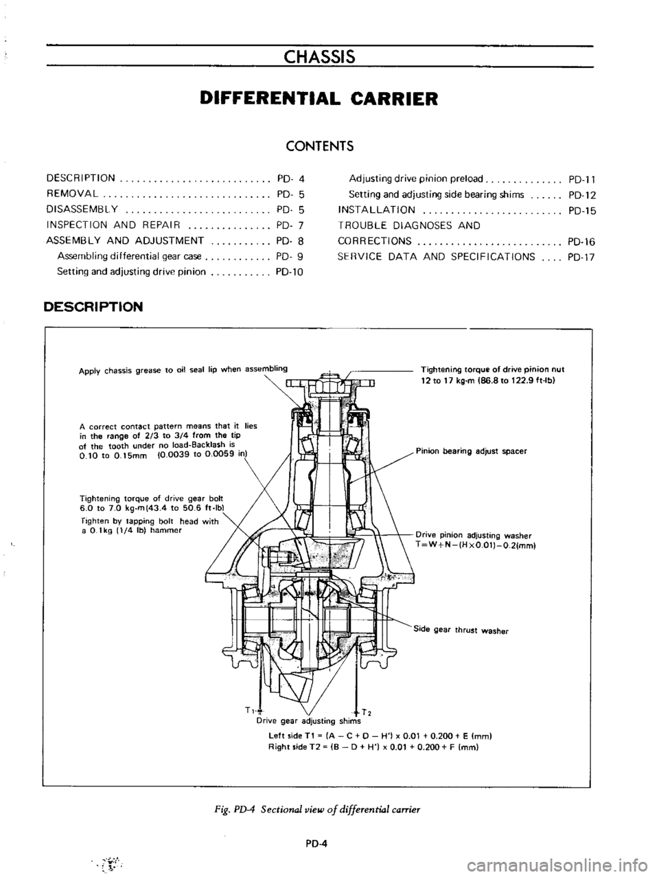
Apply
chassis
grease
to
oil
seal
lip
when
assembling
Tightening
torque
of
drive
pinion
nut
12
to
17
kg
m
86
8
to
122
9
ft
Ib
A
correct
contact
pattern
means
that
it
lies
in
the
range
of
213
to
3
4
from
the
tip
of
the
tooth
under
no
load
Backlash
is
O
10
to
0
15mm
10
0039
to
0
0059
in
Pinion
bearing
adjust
spacer
Tightening
torque
of
drive
gear
bolt
6
0
to
7
0
kg
m
43
4
to
50
6
ft
Ibl
Tighten
by
tapping
bolt
head
with
a
0
1
kg
1
4
Ib
hammer
Drive
pinion
adjusting
washer
T
W
N
IH
xO
OlJ
O
21mml
Side
gear
thrust
washer
Left
side
T1
A
C
0
H
j
x
0
01
0
200
E
mm
Right
side
T2
B
0
H
0
01
0
200
F
mm
Fig
PD
4
Sectional
view
of
differential
carrier
PD
4
Y
I
PD
l1
PD
12
PD
15
PD
16
PD
17
Page 84 of 513

PROPELLER
SHAFT
DIFFERENTIAL
CARRIER
Incorrect
adjustment
of
bearings
or
gears
Severe
service
due
to
an
excessive
loading
improper
use
of
clutch
Loosened
bolts
and
nuts
such
as
ring
gear
clamp
bolts
Oil
leakage
Worn
out
damaged
or
improperly
driven
front
oil
seal
or
bruised
dented
or
abnormally
worn
slide
face
of
companion
flange
Loosened
bolts
holding
gear
carrier
Defective
gasket
Loosen
filler
or
drain
plug
Clogged
or
damaged
breather
SERVICE
DATA
AND
SPECIFICATIONS
Type
of
differential
gear
carrier
assembly
Final
gear
type
Final
gear
ratio
number
of
teeth
Sedan
Coupe
Van
Drive
pinion
Preload
with
oil
seal
Preload
without
oil
seal
Thickness
of
drive
pinion
adjusting
shims
kg
cm
in
lb
kg
cm
in
lb
mm
in
Pinion
bearing
adjusting
spacer
Ring
gear
Backlash
between
ring
gear
and
pinion
Run
out
of
rear
side
of
ring
gear
mm
in
mm
in
Side
gear
and
pinion
mate
Thickness
of
side
gear
thrust
washers
mm
in
PD
17
Replace
defective
parts
Replace
defective
parts
Replace
defective
parts
Replace
the
defective
oil
seal
Ammend
the
affected
flange
with
sand
paper
or
replace
if
necessary
Tighten
the
bolts
to
specified
torque
Replace
defective
parts
with
new
ones
Tighten
the
plug
Repair
or
replace
H145A
Hypoid
3
900
39
10
7
to
9
6
1
to
7
8
6
to
8
5
2
to
6
9
From
2
74
to
3
25
0
1079
to
0
1280
Spacing
0
Q3
0
0012
Non
adjustable
collapsible
spacer
0
10
to
0
15
0
0039
to
0
0059
Less
than
0
05
0
0020
0
76
to
0
91
0
0299
to
0
0358
Page 85 of 513
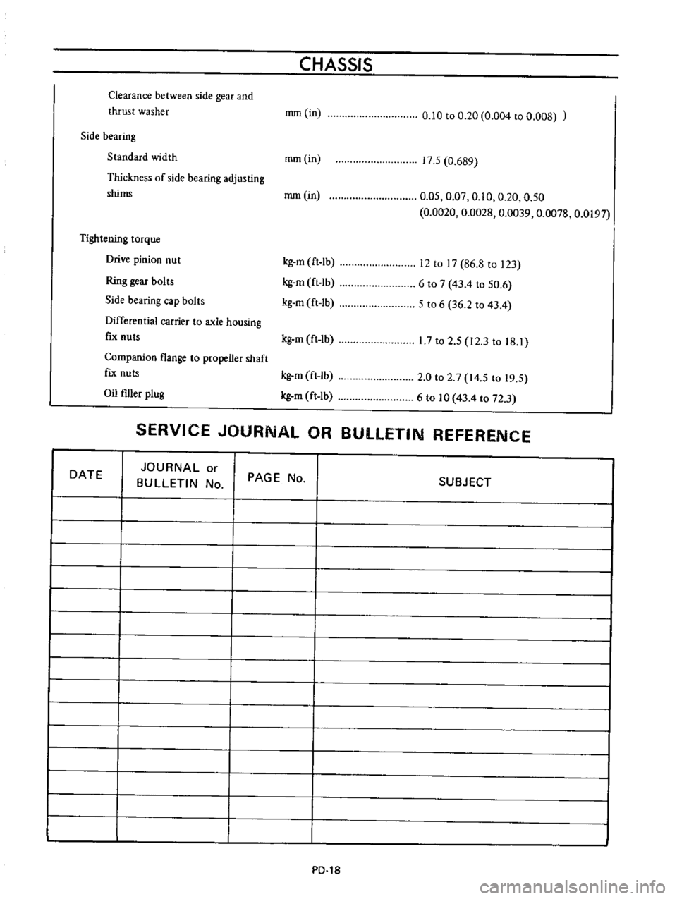
Clearance
between
side
gear
and
thrust
washer
CHASSIS
rrun
in
0
10
to
0
20
0
004
to
0
008
Side
bearing
Standard
width
rom
in
Thickness
of
side
bearing
adjusting
shims
rom
in
Tightening
torque
Drive
pinion
nut
Ring
gear
bolts
Side
bearing
cap
bolts
Differential
carrier
to
axle
housing
fIx
nuts
Companion
flange
to
propeller
shaft
fIx
nuts
Oil
filler
plug
17
5
0
689
0
05
0
07
0
10
0
20
0
50
0
0020
0
0028
0
0039
0
0078
0
0197
kg
m
ft
lb
kg
m
ft
lb
kg
m
ft
lb
12
to
17
86
8
to
123
6
to
7
43
4
to
50
6
5
to
6
36
2
to
43
4
kg
m
ft
1b
17
to
2
5
12
3
to
18
1
kg
m
ft
lb
kg
m
ft
lb
2
0
to
2
7
14
5
to
19
5
6
to
10
43
4
to
72
3
SERVICE
JOURNAL
OR
BULLETIN
REFERENCE
DATE
JOURNAL
or
BULLETIN
No
I
I
I
I
PAGE
No
SUBJECT
PO
1S
Page 86 of 513
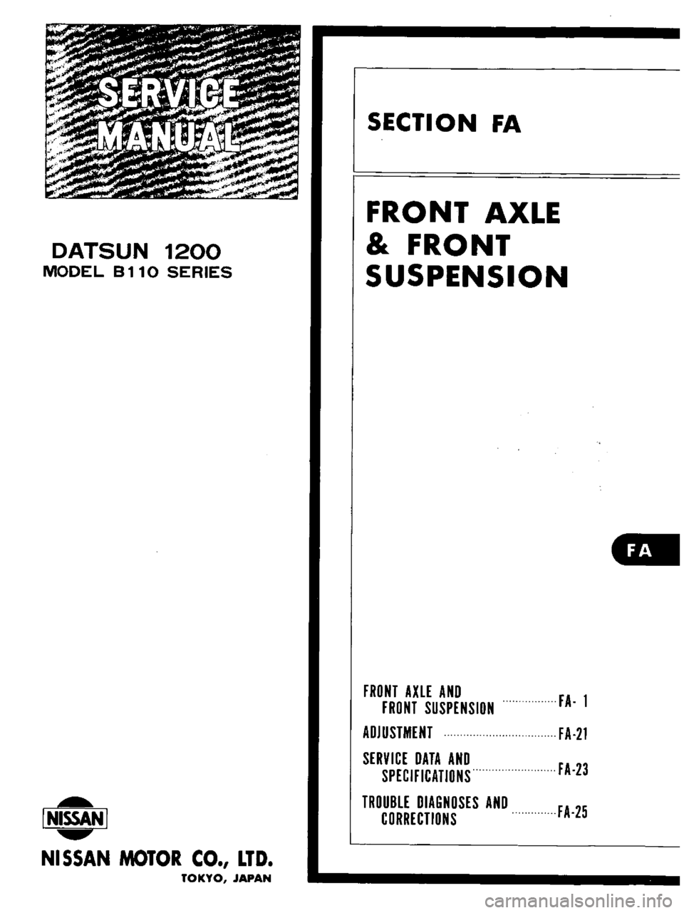
DATSUN
1200
MODEL
B
110
SERIES
I
NISSAN
I
NISSAN
MOTOR
CO
LTD
TOKYO
JAPAN
SECTION
FA
FRONT
AXLE
FRONT
SUSPENSION
all
FRONT
AXLE
AND
FRONT
SUSPENSION
ADJUSTMENT
SERVICE
DATA
AND
SPECIFICATIONS
TROUBLE
DIAGNOSES
AND
CORRECTIONS
FA
1
FA
21
FA
23
FA
25