1973 DATSUN B110 service
[x] Cancel search: servicePage 161 of 513
STEERING
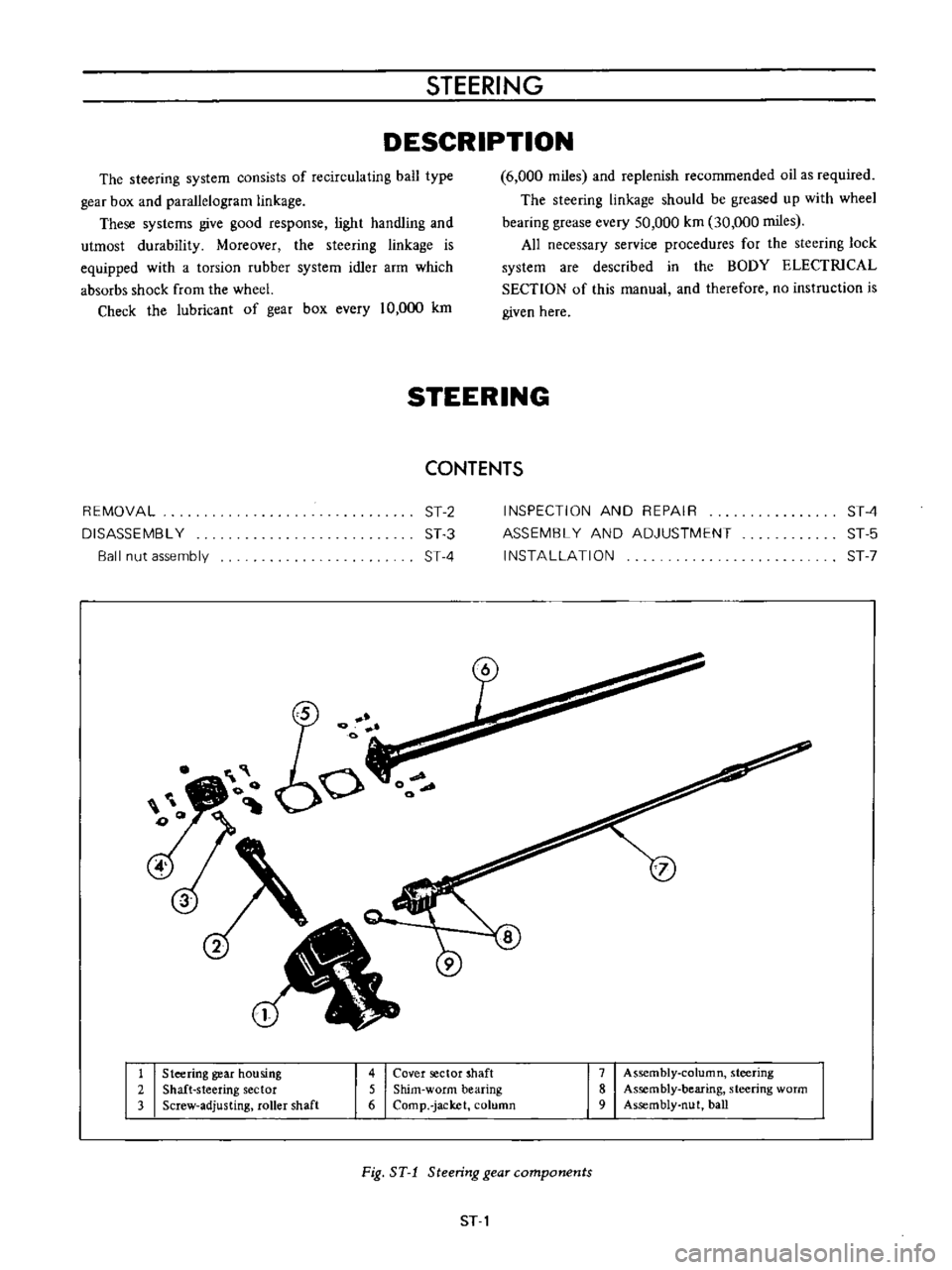
DESCRIPTION
The
steering
system
consists
of
recirculating
ball
type
gear
box
and
parallelogram
linkage
These
systems
give
good
response
light
handling
and
utmost
durability
Moreover
the
steering
linkage
is
equipped
with
a
torsion
rubber
system
idler
arm
which
absorbs
shock
from
the
wheel
Check
the
lubricant
of
gear
box
every
10
000
km
6
000
miles
and
replenish
recommended
oil
as
required
The
steering
linkage
should
be
greased
up
with
wheel
bearing
grease
every
50
000
km
30
000
miles
All
necessary
service
procedures
for
the
steering
lock
system
are
described
in
the
BODY
ELECTRICAL
SECTION
of
this
manual
and
therefore
no
instruction
is
given
here
STEERING
CONTENTS
REMOVAL
DISASSEMBL
Y
Ball
nut
assembly
ST
2
ST
3
ST
4
INSPECTION
AND
REPAIR
ASSEMBL
Y
AND
ADJUSTMENT
INSTALLATION
ST
4
ST
5
ST
7
1
Steering
gear
housing
2
Shaft
steering
sector
3
Screw
adjusting
roller
shaft
4
Cover
sector
shaft
5
Shim
worm
bearing
6
Comp
jacket
column
7
Assembly
column
steering
8
Assembly
bearing
steering
worm
9
Assembly
nut
ball
Fig
ST
1
Steering
gear
components
ST
1
Page 177 of 513
STEERING
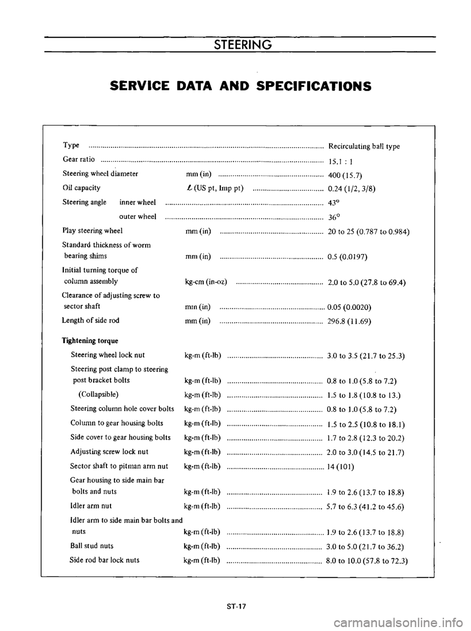
SERVICE
DATA
AND
SPECIFICATIONS
Type
Gear
ratio
Steering
wheel
diameter
Oil
capacity
Steering
angle
inner
wheel
outer
wheel
Play
steering
wheel
Standard
thickness
of
worrn
bearing
shims
Initial
turning
torque
of
column
assembly
Clearance
of
adjusting
screw
to
sector
shaft
Length
of
side
rod
Tightening
torque
Steering
wheel
lock
nut
Steering
post
clamp
to
steering
post
bracket
bolls
Collapsible
Steering
column
hole
cover
bolts
Column
to
gear
housing
bolts
Side
cover
to
gear
housing
bolts
Adjusting
screw
lock
nut
Sector
shaft
to
pitman
arm
nut
Gear
housing
to
side
main
bar
bolts
and
nuts
Idler
arm
nut
Recirculating
ball
type
mm
in
L
US
pt
Imp
pt
15
I
I
400
157
0
24
I
2
3
8
430
360
mm
in
20
to
25
0
787
to
0
984
mm
in
0
5
0
0197
kg
em
in
oz
2
0
to
5
0
27
8
to
69
4
mrn
in
mm
in
0
05
0
0020
296
8
11
69
kg
m
ft
lb
3
0
to
3
5
217
to
25
3
kg
m
ft
lb
kg
m
ft
Ib
kg
m
ft
lb
kg
m
ft
lb
kg
m
ft
lb
kg
m
ft
lb
kg
m
ft
lb
0
8
to
1
0
5
8
to
7
2
1
5
to
1
8
10
8
to
13
0
8
to
1
0
5
8
to
7
2
1
5
to
2
5
10
8
to
18
1
I
7
to
2
8
12
3
to
20
2
2
0
to
3
0
14
5
to
21
7
14
101
kg
m
ft
lb
kg
m
ft
lb
1
9
to
2
6
13
7
to
18
8
57
to
6
3
41
2
to
45
6
Idler
arm
to
side
main
bar
bolts
and
nuts
kg
m
ft
Ib
Ball
stud
nuts
kg
m
ft
lb
Side
rod
bar
lock
nuts
kg
m
ft
lb
1
9
to
2
6
13
7
to
18
8
3
0
to
5
0
21
7
to
36
2
8
0
to
10
0
57
8
to
72
3
ST
17
Page 188 of 513
DATE
ENGINE
CONTROL
FUEL
EXHAUST
SYSTEM
VAN
ONLY
r
j
f
Qo
I
e
nr
e
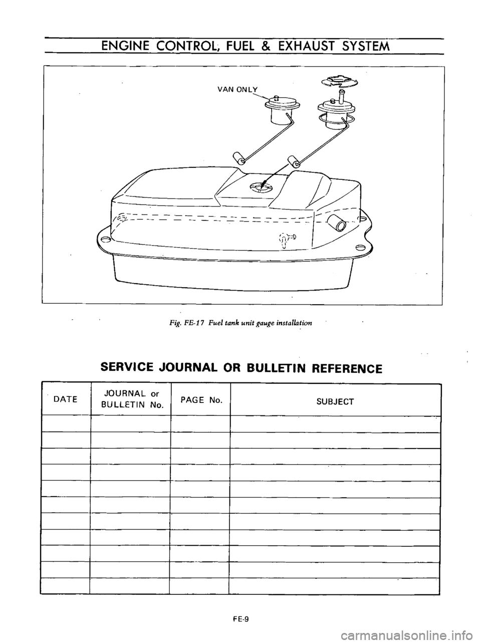
Fig
FE
17
Fuel
tank
unit
gauge
installation
SERVICE
JOURNAL
OR
BULLETIN
REFERENCE
JOURNAL
or
BULLETIN
No
PAGE
No
SUBJECT
FE
9
Page 189 of 513
DATE
CHASSIS
SERVICE
JOURNAL
OR
BUllETIN
REFERENCE
JOURNAL
or
BULLETIN
No
PAGE
No
SUBJECT
FE
10
Page 199 of 513
BODY
UNDERBODY
ALIGNMENT
CONTENTS
UNDERBODY
GENERAL
SERVICE
INFORMATION
ALIGNMENT
CHECKING
PROCEDURE
BF
9
BF
9
UNDERBODY
GENERAL
SERVICE
INFORMATION
Since
each
underbody
component
directly
affects
the
overall
strength
of
the
body
it
is
essential
that
proper
welding
sealing
and
rust
proofing
techniques
be
observed
during
service
operations
Whenever
the
body
is
repaired
be
sure
to
provide
the
repaired
body
parts
with
rust
proof
In
the
case
of
a
rust
proofmg
critical
underbody
component
it
is
essential
that
a
good
quality
type
air
dry
primer
such
as
corrosion
resistant
zinc
chromate
be
used
Do
not
use
combination
type
primer
surfacers
ALIGNMENT
CHECKING
PROCEDURE
Misalignment
in
the
underbody
affects
the
front
fender
door
trunk
lid
and
window
alignments
and
also
the
tail
gate
and
rear
body
opening
alignments
in
the
case
of
a
station
wagon
or
van
Underbody
misalignment
particularly
affects
the
suspension
system
thereby
causing
various
problems
that
arise
from
suspension
misalignment
It
is
essential
that
underbody
components
be
aligned
within
the
specified
dimensions
given
in
Figures
BF
13
14
and
IS
In
the
event
of
collision
damage
it
is
important
that
underbody
a1ignrnent
be
thoroughly
checked
and
if
necessary
realigned
to
the
specified
dirnensions
There
are
many
tools
that
may
be
ernployed
to
correct
collision
damage
such
as
frame
straightening
machines
external
pulling
equipment
other
standard
body
jacks
PRINCIPLES
OF
TRAMMING
CAR
PREPARATION
TRAMMING
SEQUENCE
BF
9
BF
10
BF
10
To
assist
in
checking
alignment
of
the
underbody
components
repairing
minor
underbody
damage
or
locating
replacement
parts
the
following
underbody
dimensions
and
alignment
checking
information
are
presented
PRINCIPLES
OF
TRAMMING
All
reference
locations
shown
in
Figure
BF
13
14
and
15
are
symmetrical
at
the
centerline
of
the
vehicle
For
example
wheo
performing
a
crosHheck
of
the
body
floor
panel
dimensions
Figures
BF
I3
14
and
IS
the
diagonal
measurement
should
be
the
same
in
boflii
directions
Cross
checking
operations
are
used
to
deter
mine
the
relationship
between
two
locations
on
the
underbody
To
measure
the
distance
between
any
two
reference
points
on
the
underbody
accurately
two
specifications
are
required
I
The
horizontal
dimension
between
the
two
points
to
be
measured
2
The
vertical
dimension
from
the
datum
line
to
the
points
to
be
measured
For
an
example
the
diagonal
measurement
calculated
on
a
horizontal
plane
between
reference
points
of
dimension
line
L
shown
in
Figure
BF
I3
is
631
3
mm
24
8
in
The
specifications
from
the
datum
line
have
a
vertical
height
difference
of
11
6
mm
0
456
in
between
the
forward
location
of
dimension
L
at
vertical
dimension
80
0
mm
3
150
in
and
the
rearward
location
of
dimension
L
at
vertical
dimension
91
6
mm
3
606
in
The
vertical
pointer
used
at
the
forward
location
should
be
positioned
so
as
to
extend
11
6
mm
0
456
in
further
from
the
tram
bar
than
the
BF
9
Page 216 of 513
Removal
I
t
is
recommended
that
the
door
be
removed
from
the
body
with
the
door
hinges
attached
on
the
door
although
the
door
may
be
removed
from
the
body
with
or
without
the
hinges
attached
on
the
door
Front
door
Remove
the
package
tray
2
Remove
the
door
hinge
service
hole
cover
from
the
dash
side
trim
3
With
the
door
fully
opened
support
the
door
by
applying
a
stand
or
jack
beneath
the
door
so
that
the
door
does
not
drop
off
Note
Apply
a
piece
of
rag
between
the
door
and
stand
so
that
the
door
panel
is
protected
from
damaging
4
Remove
the
door
hinge
installation
bolts
at
the
body
side
by
the
use
of
a
box
wrench
and
remove
the
door
from
the
body
Fig
BF
45
Removing
front
door
Dash
side
trim
without
door
hinge
sevice
hole
Rear
door
Remove
the
kicking
plate
2
Peel
off
the
body
side
welt
and
remove
the
center
pillar
finish
BODY
3
Hereinafter
follow
the
instructions
for
the
front
door
and
remove
the
rear
door
11
I
fl
C
I
r
r
I
W
I
r
I
I
dl
J
Ik
I
h
I
l
i
J
n
Fig
BF
46
Removing
rear
door
Adjustment
Door
hinge
Loosen
the
bolts
used
to
secure
the
hinge
to
the
body
adjust
the
door
upward
downward
forward
or
rear
ward
position
as
required
and
retighten
the
bolts
securely
Adjustable
range
6
mm
0
2362
in
Tightening
torque
Hinge
pillar
installation
bolt
1
6
kg
m
11
6
ft
lb
Hinge
door
installation
bolt
1
6
kg
m
11
6
ft
lb
Note
a
When
installing
the
hinge
grease
the
hinge
link
b
Oil
top
of
the
hinge
pin
when
the
door
squeaks
while
opening
or
closing
Striker
Another
method
to
adjust
the
door
loosen
the
striker
fixing
screw
and
adjust
the
striker
position
Adjustable
range
6
mm
0
2362
in
Tightening
torque
Striker
installation
machine
screw
0
12
to
0
2
kg
m
0
7
to
I
4
ft
lb
BF
26
Page 218 of 513
IT
f
r
J
e
@
@
BODY
Door
lock
2
I
nside
handle
3
Escu
tcheon
4
Door
lock
knob
5
Knob
grommet
Front
door
lock
removal
Fig
BF
51
Rear
door
lock
mechanism
Remove
the
parts
up
to
the
seal
screen
2
Remove
the
door
lock
knob
and
then
remove
the
remote
control
rod
used
to
connect
the
door
lock
to
the
door
lock
cylinder
from
the
door
lock
cylinder
3
Remove
the
inside
handle
installation
screw
and
the
door
lock
assembly
installation
screws
and
withdraw
the
outside
handle
rod
from
the
opening
on
the
lock
assembly
Remove
the
lock
assembly
from
the
service
hole
on
the
inside
panel
I
I
Lock
knob
Inside
handLe
I
3
I
Lock
assembly
Fig
BF
52
Door
wUhout
sealing
screen
4
Detach
the
leaf
clip
used
to
secure
the
lock
cylinder
on
the
door
and
remove
the
lock
cylinder
Fig
BF
53
Removing
front
door
lock
Front
door
lock
installation
1
Installing
the
inside
handle
and
remote
control
Adjust
position
and
install
the
remote
control
so
that
the
Slopper
@
ofthe
inside
handle
Q
lightly
contacts
the
base
plate
of
the
door
lock
CD
If
the
remote
control
is
installed
with
the
inside
handle
Q
pulled
the
locking
plate
@
doesnotintermesh
with
the
ratchet
completely
at
the
full
ratch
and
the
lock
knob
j
does
not
lower
2
Connecting
outside
handle
to
the
locking
plate
Set
the
locking
plate
@lto
the
fully
ratched
position
insert
the
nylon
nut
@
on
the
end
of
the
outside
handle
rod
ID
into
the
locking
plate
hole
@
and
adjust
and
secure
the
nylon
nut
@
with
adhesive
in
a
position
where
BF
28
Page 220 of 513
BODY
i
1
Rear
door
panel
2
Glass
run
rubber
3
Partition
rear
door
weatherstrip
4
Rear
door
glass
5
Rear
door
corner
glass
6
Glazing
rubber
7
Bottom
channel
8
Door
window
regulator
9
Door
handle
washer
10
Door
window
regulator
handle
91
W
10
Fig
BF
56
Rear
door
glass
and
regulator
construction
4
door
Sedan
Removal
Remove
the
door
trim
and
seal
screen
2
Rernove
the
door
glass
stopper
and
lower
the
door
glass
to
the
bottorn
3
Remove
four
door
ventilator
installation
screws
and
detach
the
door
ventilator
Fig
BF
57
Removing
door
ventilator
4
Pull
upward
and
remove
the
door
glass
5
Remove
three
regulator
assembly
installation
screws
and
remove
the
regulator
assembly
from
the
service
hole
Note
The
door
regulator
may
be
removed
without
removing
the
door
lock
Fig
BF
58
Removing
rear
door
window
regulator
BF
30