Page 93 of 513
FRONT
AXLE
FRONT
SUSPENSION
10
Remove
four
brake
disc
fitting
bolts
and
remove
the
brake
disc
rotor
from
the
wheel
hub
assembly
Disc
type
b
rake
Inspection
1
Grease
seal
I
ycQ
r
A
1
r
j
t
I
I
i
I
When
grease
leakage
is
delected
during
disassembly
replace
2
Replace
the
grease
seal
with
a
new
one
if
worn
or
cracked
Fig
FA
21
Removing
brake
disc
rotor
2
Wheel
bearing
Remove
used
grease
from
the
wheel
bearing
with
solvent
and
inspect
the
bearing
for
operating
condition
from
the
rotation
operating
sound
and
appearance
The
outer
race
may
be
checked
for
the
condition
of
rolling
surface
with
the
race
installed
on
the
wheel
hub
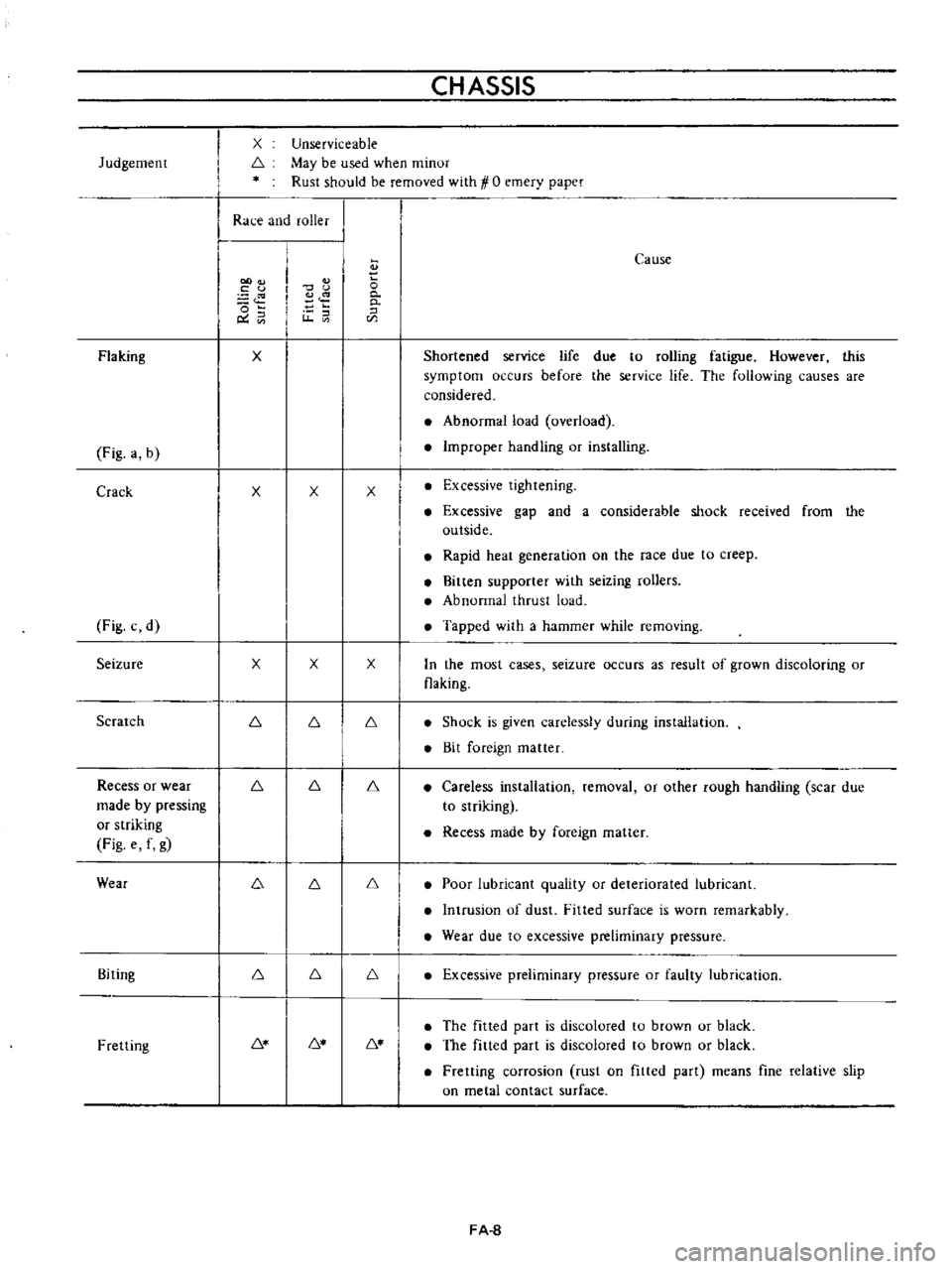
Visual
serviceability
judgement
standard
for
the
wheel
bearing
is
indicated
in
the
following
table
Visual
Serviceability
Judg
ment
Standard
for
Wheel
Bearing
INNER
RACE
SURFACE
OUTER
RACE
FITTED
SURFACE
COLLAR
SURFACE
OUTER
RACE
SURFACE
INNER
RACE
FITTED
ROLLER
ROLLING
SURFACE
SURFACE
SMALL
COLLAR
INNER
RACE
LARGE
COLLAR
ROLLER
SUPPORTER
OUTER
RACE
FA
7
Page 94 of 513

Judgemenr
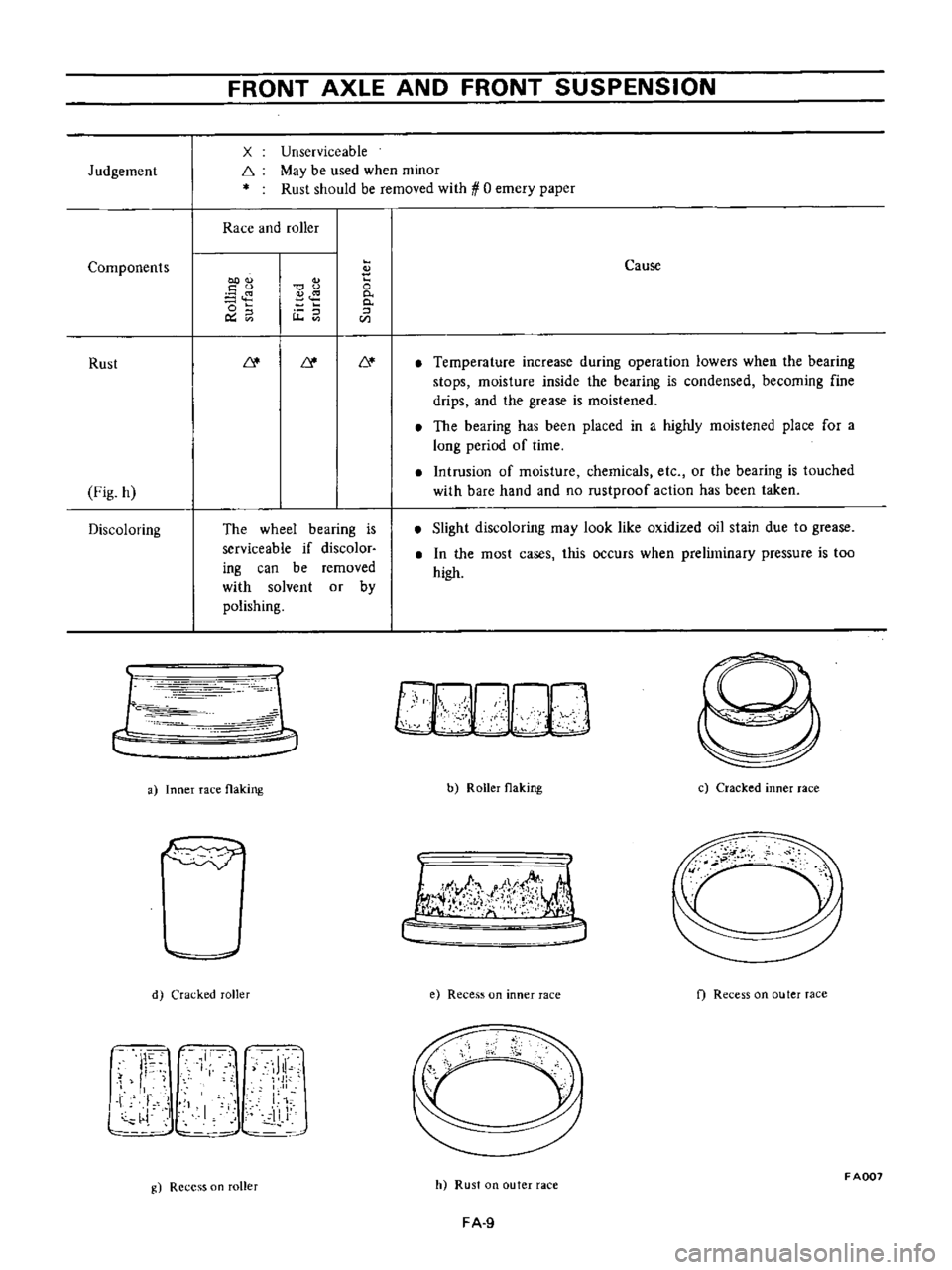
Flaking
Fig
a
b
Crack
Fig
c
d
Seizure
Scratch
Recess
or
wear
made
by
pressing
or
striking
Fig
e
f
g
Wear
Biting
Fretting
CHASSIS
Unserviceable
May
be
used
when
minor
Rust
should
be
removed
with
1
0
emery
paper
X
6
Race
and
roller
oo
c
u
o
C
U
x
x
x
6
6
6
6
6
x
x
6
6
6
6
6
o
0
0
Cause
Shortened
service
life
due
to
rolling
fatigue
However
this
symptom
occurs
before
the
service
life
The
following
causes
are
considered
Abnormal
load
overload
Improper
handling
or
installing
x
Excessive
tighrening
Excessive
gap
and
a
considerable
shock
received
from
the
outside
Rapid
hear
generation
on
the
race
due
to
creep
Bitten
supporter
with
seizing
rollers
Abnormal
thrust
load
Tapped
with
a
hammer
while
removing
x
In
the
most
cases
seizure
occurs
as
result
of
grown
discoloring
or
flaking
6
Shock
is
given
carelessly
during
installation
Bit
foreign
matter
6
Careless
installation
removal
or
other
rough
handling
scar
due
to
striking
Recess
made
by
foreign
matter
6
Poor
lubricant
quality
or
deteriorated
lubricant
Intrusion
of
dust
Fitted
surface
is
worn
remarkably
Wear
due
to
excessive
preliminary
pressure
6
Excessive
preliminary
pressure
or
faulty
lubrication
6
The
fitted
part
is
discolored
to
brown
ur
black
The
fitted
part
is
discolored
to
brown
or
black
Fretting
corrosion
rust
on
fitted
part
means
fine
relative
slip
on
metal
contact
surface
FA
8
Page 95 of 513

Judgement
Components
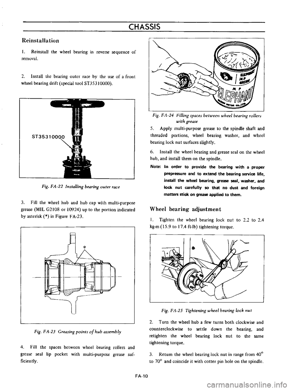
Rust
Fig
h
Discoloring
FRONT
AXLE
AND
FRONT
SUSPENSION
x
f
Unserviceable
May
be
used
when
minor
Rust
should
be
removed
with
0
emery
paper
Race
and
roller
00
u
o
o
Ou
u
The
wheel
bearing
is
serviceable
if
discolor
ing
can
be
removed
with
solvent
or
by
polishing
r
c
1
1
Ie
r
r
iJ
a
Inner
race
flaking
d
Cracked
roller
J
I
11
Ji
l
L
i
I
11
J
g
Recess
on
roller
o
0
0
CIl
Cause
Temperature
increase
during
operation
lowers
when
the
bearing
stops
moisture
inside
the
bearing
is
condensed
becoming
fine
drips
and
the
grease
is
moistened
The
bearing
has
been
placed
in
a
highly
moistened
place
for
a
long
period
of
time
Intrusion
of
moisture
chemicals
etc
or
the
bearing
is
touched
with
bare
hand
and
no
rustproof
action
has
been
taken
Slight
discoloring
may
look
like
oxidized
oil
stain
due
to
grease
In
the
most
cases
this
occurs
when
preliminary
pressure
is
too
high
b
Roller
flaking
c
Cracked
inner
race
I
lJ
f
t
j
e
Recess
on
inner
race
f
Recess
on
outer
race
cc
h
Rust
on
outer
race
FADD7
FA
9
Page 96 of 513

CHASSIS
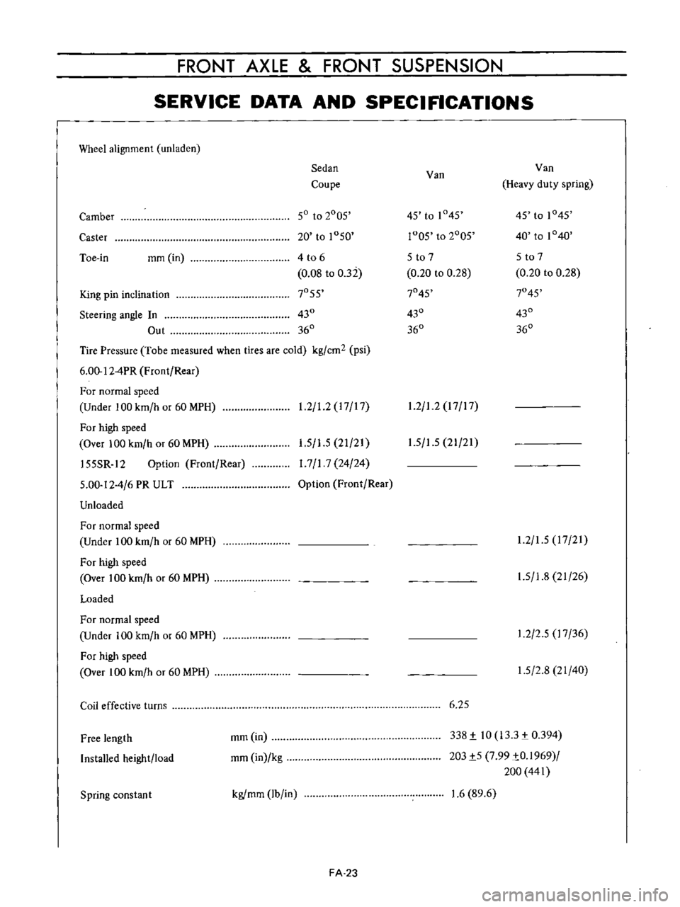
Reinstallation
Reinstall
the
wheel
bearing
in
reverse
sequence
of
removal
2
Install
the
bearing
outer
race
by
the
use
of
a
froot
wheel
bearing
drift
special
tool
ST353
10000
Fig
FA
22
Installing
bearing
outer
race
3
Fill
the
wheel
hub
and
hub
cap
with
multi
purpose
grease
MIL
G2108
or
10924
up
to
the
portion
indicated
by
asterisk
in
Figure
F
A
23
l
I
L
I
I
P
p
r
Fig
FA
23
Greasing
points
of
hub
assembly
4
Fill
the
spaces
between
wheel
bearing
rollers
and
grease
seal
lip
pocket
with
multi
purpose
grease
suf
ficiently
FA
10
Fig
FA
24
Filling
spaces
betweetJ
wheel
bearing
rollers
with
grease
5
Apply
multi
purpose
grease
to
the
spindle
shaft
and
threaded
portions
wheel
bearing
washer
and
wheel
bearing
lock
nut
surfaces
slightly
6
Install
the
wheei
bearing
and
grease
seal
on
the
wheel
hub
and
install
them
on
the
spindle
Note
In
order
to
provide
the
bearing
with
a
proper
prepressure
and
to
extend
the
bearing
service
life
install
the
wheel
bearing
grease
seal
washer
and
lock
nut
carefully
so
that
no
dust
and
foreign
matters
stick
on
grease
applied
to
them
Wheel
bearing
adjustment
I
Tighten
the
wheel
bearing
lock
nut
to
2
2
to
2
4
kg
m
15
9
to
174
ft
lb
tightening
torque
Fig
FA
25
Tightening
wheel
bearing
lock
nut
2
Turn
the
wheel
hub
a
few
turns
both
clockwise
and
counterclockwise
to
settle
down
the
bearing
and
retighten
the
wheel
bearing
lock
nut
to
the
same
tightening
torque
3
Return
the
wheel
bearing
lock
nut
in
range
from
400
to
700
and
coincide
it
with
cotter
pin
hole
on
the
spindle
Page 109 of 513

FRONT
AXLE
FRONT
SUSPENSION
SERVICE
DATA
AND
SPECIFICATIONS
Wheel
alignment
unladen
Sedan
Van
Van
Coupe
Heavy
duty
spring
Camber
50
to
2005
45
to
1
45
45
to
1045
Caster
20
to
1050
r005
to
2005
40
to
1040
Toe
in
mm
in
4
t06
5
to
7
5
to
7
0
08
to
032
0
20
to
0
28
0
20
to
0
28
King
pin
inclination
7055
7045
7045
Steering
angle
In
430
430
430
Out
360
360
360
Tire
Pressure
Tobe
measured
when
tires
are
cold
kg
cm2
psi
6
00
12
4PR
Front
Rear
For
normal
speed
Under
100
km
h
or
60
MPH
1
2
1
2
17
17
1
2
1
2
17
17
For
high
speed
Over
100
km
h
or
60
MPH
155SR
12
Option
Front
Rear
5
00
12
4
6
PR
ULT
Unloaded
1
5
1
5
21
21
1
7
1
7
24
24
Option
Front
Rear
1
5
1
5
21
21
For
normal
speed
Under
100
km
h
or
60
MPH
For
high
speed
Over
100
km
h
or
60
MPH
Loaded
1
2
1
5
17
21
1
5
1
8
21
26
For
normal
speed
Under
100
km
h
or
60
MPH
For
high
speed
Over
100
km
h
or
60
MPH
1
2
2
5
17
36
1
5
2
8
21
40
Coil
effective
turns
6
25
Free
length
Installed
height
load
mm
in
mm
in
kg
338
i
10
133
0394
203i5
7
99
iO
1969
200
441
Spring
constan
t
kgfmm
lb
in
1
6
89
6
FA
23
Page 114 of 513
CHASSIS
Jumping
of
disc
wheel
Improper
air
pressure
of
tire
Adjust
Unbalanced
wheels
Adjust
Defective
shock
absorber
Replace
Defective
tire
Replace
Deformed
wheel
rim
Replace
Excessively
or
partially
worn
tire
Improper
air
pressure
of
tire
Adjust
Incorrect
wheel
alignment
Adjust
Defective
wheel
bearing
Replace
Incorrect
brake
adjustment
Adjust
Improper
tire
shifting
rotation
Adjust
Rough
and
improper
driving
manner
Drive
more
gently
SERVICE
JOURNAL
OR
BULLETIN
REFERENCE
DATE
JOURNAL
or
BULLETIN
No
PAGE
No
SUBJECT
FA
28
Page 115 of 513
DATSUN
1200
MODEL
B
1
10
SERIES
I
NISSAN
I
NISSAN
MOTOR
CO
LTD
TOKYO
JAPAN
SECTION
RA
REAR
AXLE
REAR
SUSPENSION
REAR
AXLE
REAR
SUSPENSION
SERVICE
DATA
AND
SPECIFICATIONS
RA
1
RA
4
RA
7
Page 116 of 513
REAR
AXLE
REAR
SUSPENSION
REAR
AXLE
CONTENTS
DESCRIPTION
REAR
AXLE
SHAFTS
Removal
RA
1
RA
l
RA
l
8
Inspection
Assembly
RA
3
RA
3
1
Axle
shaft
2
Spacer
3
Wheel
bearing
4
Wheel
bearing
collar
5
Oil
seal
6
Bearing
adjust
shim
7
Axle
case
8
Brake
drum
DESCRIPTION
Fig
RA
l
Sectional
view
of
rear
axle
The
rear
axle
is
of
a
semi
floating
type
The
axle
housing
is
a
press
steel
Banjo
type
housing
It
is
light
in
weight
and
is
sufficiently
strong
to
withstand
all
torsional
and
bending
loads
The
rear
wheel
bearings
are
of
presea1ed
types
There
fore
no
frequent
lubricating
service
is
required
However
when
the
rear
axle
is
disassembled
the
wheel
bearings
should
be
packed
with
an
approved
grease
prior
io
the
reinstallation
being
careful
not
to
damage
the
sealing
rubber
REAR
AXLE
SHAFTS
Removal
Apply
wheel
chocks
on
front
wheels
jack
up
the
rear
of
the
vehicle
and
support
it
on
stands
RA
l