1973 DATSUN B110 service
[x] Cancel search: servicePage 228 of 513
@
c
@
CD
w
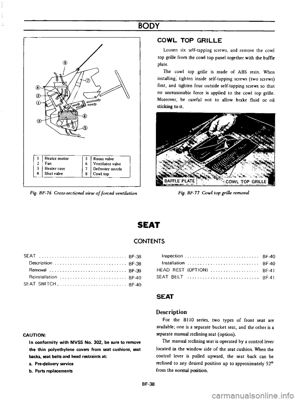
1
Heater
motor
2
Fan
3
Heater
core
4
Shut
valve
5
Room
valve
6
Ventilator
valve
7
Defroster
nozzle
8
Cowl
top
Fig
BF
76
Cross
sectional
view
of
forced
ventilation
BODY
COWL
TOP
GRILLE
Loosen
six
self
tapping
screws
and
remove
the
cowl
top
grille
from
the
cowl
top
panel
together
with
the
baffle
plate
The
cowl
top
grille
is
made
of
ABS
resin
When
installing
tighten
inside
self
tapping
screws
two
screws
first
and
lighten
four
outside
self
tapping
screws
so
that
no
unreasonable
force
is
applied
to
the
cowl
top
grille
Moreover
be
careful
not
to
allow
brake
fluid
or
oil
sticking
to
it
Fig
BF
77
Cowl
top
grille
removal
SEAT
CONTENTS
SEAT
Description
Removal
Reinstallation
SEAT
SWI
TCH
BF
38
BF
38
BF
39
BF
40
BF
40
CAUTION
I
n
conformity
with
MVSS
No
302
be
sure
to
remove
the
thin
polyethylene
covers
from
seat
cushions
seat
backs
seat
belts
and
head
restraints
at
a
Pi
Helivery
service
b
Parts
replacements
Inspection
Installation
HEAD
REST
OPTIONI
SEAT
BELT
BF
40
BF
40
BF
41
BF
41
SEAT
Description
For
the
BHO
series
two
types
of
front
seat
are
available
one
is
a
separate
bucket
seat
and
the
other
is
a
separate
manual
reclining
seat
option
The
manual
reclining
seat
is
operated
by
a
control
lever
located
in
the
window
side
of
the
seat
cushion
When
the
control
lever
is
pulled
upward
the
seat
back
can
be
reclined
to
any
desired
position
up
to
approximately
520
from
the
normal
position
BF
38
Page 231 of 513

j
L
CD
1
II
r
1
P
r
4vc
V
4
I
o
@
@
c
ID
I
HEAD
REST
OPTION
When
installing
head
rest
on
front
seat
remove
the
plug
on
the
seat
back
and
insert
the
head
rest
supports
into
the
holes
Fig
BF
86
Head
rest
BODY
SEAT
BELT
The
two
front
seat
belts
are
of
a
three
point
type
consisting
of
lap
and
shoulder
belts
The
two
rear
seat
belts
are
of
a
tow
point
type
The
lap
belts
of
all
seats
are
provided
with
automatic
locking
retractor
In
the
front
automatic
locking
retaractor
a
belt
switch
retractor
switch
micro
switch
for
the
seat
belt
warning
system
is
built
in
Notes
a
DO
NOT
attempt
repairs
on
lap
belt
retractor
mechanisms
Replace
defective
part
with
NEW
service
replacement
parts
b
DO
NOT
replace
one
belt
of
lap
belt
or
shou
Ider
belt
set
r
l
Scating
switch
for
assistant
seat
2
Seat
belt
switch
3
Automatic
locking
retractor
4
Inhibitor
switch
for
AfT
5
Neutral
switch
for
M
T
Fig
BF
87
Seat
belt
installing
positions
BF
41
Page 241 of 513
INSPECTION
Referring
to
the
wiring
diagram
check
the
wiring
harness
for
connection
with
electrical
equipment
and
connector
for
conned
ion
and
installation
When
checking
the
wiring
harness
note
the
following
matters
Connected
unit
should
not
be
loose
rusted
or
contaminated
2
Cable
insulator
cover
should
not
be
damaged
crack
ed
or
insulating
material
should
not
be
deteriorated
3
For
those
parts
which
are
grounded
through
the
installation
bolts
the
bolts
should
be
in
contact
with
the
body
completely
so
that
continuity
is
provided
in
between
the
body
and
bolts
4
Terminals
of
unit
through
which
current
flows
should
not
come
into
contact
with
other
metal
parts
5
No
erroneous
connection
should
be
present
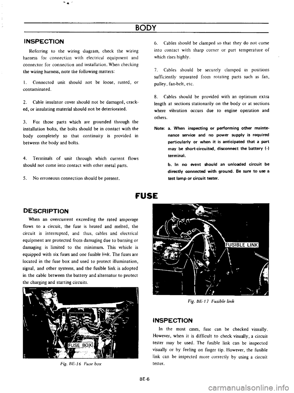
DESCRIPTION
When
an
overcunent
exceeding
the
rated
amperage
flows
to
a
circuit
the
fuse
is
heated
and
melted
the
circuit
is
interrupted
and
thus
cables
and
electrical
equipment
are
protected
from
damaging
due
to
burning
or
damaging
is
limited
to
the
minimum
This
vehicle
is
equipped
with
six
fuses
and
one
fusible
link
The
fuses
are
located
in
the
fuse
box
and
used
to
protect
illumination
signal
and
other
systems
and
the
fusible
link
is
adopted
in
the
cable
between
the
battery
and
alternator
to
protect
the
charging
and
starting
circuits
FiJ
BE
16
Fuse
box
BODY
6
Cables
should
be
damped
so
that
they
do
not
come
into
contact
with
sharp
corner
or
part
lernperature
of
which
rises
highly
7
Cables
should
be
securely
clamped
in
posItions
sufficiently
separated
from
rotating
parts
such
as
fan
pulley
fan
belt
etc
8
Cables
should
be
provided
with
an
optimum
extra
length
at
sections
stationarity
on
the
body
or
at
sections
where
vibration
occurs
due
to
engine
operation
and
others
Note
a
When
inspecting
or
performing
other
mainte
nance
service
and
no
power
supply
is
required
particularly
or
when
it
is
anticipated
that
a
part
may
be
short
circuited
disconnect
the
battery
H
terminal
b
In
no
event
should
an
unloaded
circuit
be
directly
connected
with
ground
Be
sure
to
use
a
test
lamp
or
circuit
tester
fUSE
Fig
BE
17
Fusible
link
INSPECTION
In
the
most
cases
fuse
can
be
checked
visually
However
when
it
is
difficult
to
check
visually
a
circuit
tester
may
be
used
The
fusible
link
can
be
inspected
visually
or
by
feeling
on
finger
tip
However
the
fusible
link
can
be
inspected
more
correctly
by
using
a
circuit
tester
BE
6
Page 253 of 513

BODY
METERS
AND
GAUGES
CONTENTS
CLUSTER
LID
Oescri
ption
Removal
SPEEDOMETER
Replacement
FUEL
GAUGE
AND
TEMPERATURE
GAUGE
Description
Replacement
BE
1B
BE
18
BE
18
BE
19
BE
19
BE
19
BE
19
BE
20
CLUSTER
LID
Description
The
cluster
lid
holds
various
rneters
indicators
and
clock
located
around
the
speedorneter
Printed
circuit
board
is
used
at
the
back
of
the
meter
as
shown
in
Figure
BE
38
and
the
printed
circuit
board
is
connected
with
multiple
connectors
Thus
the
meters
Can
be
inspected
and
serviced
extremely
easily
Except
for
the
speed
ometer
all
rneters
are
operated
electrically
The
fuel
gauge
and
therrnometer
are
very
reliable
and
they
are
equipped
with
bimetal
devices
F
a
o
ill
I
1
a
a
Fig
BE
34
Combination
meters
Removal
Disconnect
the
battery
terminal
depressing
the
OIL
PRESSURE
AND
IGNITION
WARNING
LAMPS
HAND
BRAKE
WARNING
LAMP
BULB
SPECIFICATIONS
TROUBLE
DIAGNOSES
AND
CORRECTIONS
Speedometer
Thermometer
and
fuel
meter
Oil
pressure
and
ignition
warning
lamps
BE
20
BE
21
BE
21
BE
22
BE
22
BE
23
BE
25
windshield
wiper
switch
lighting
switch
and
choke
lever
knobs
turn
them
counterclockwise
to
remove
Remove
the
escutcheon
2
Inserting
your
hand
into
back
of
the
cluster
lid
disconnect
the
cigarette
lighter
cable
and
turn
and
remove
the
cigarette
lighter
outer
case
3
Remove
the
radio
and
heater
control
knobs
4
Remove
the
shell
cover
from
the
steering
tube
loosen
the
screws
used
to
secure
the
meter
housing
to
the
instrument
panel
and
remove
the
cluster
lid
5
Pull
out
the
l2
pole
round
shape
connector
and
remove
the
speedometer
cable
union
nut
6
Remove
the
cluster
lid
from
the
instrument
panel
Fig
BE
35
Removing
clllSter
jd
BE
18
Page 256 of 513

BODY
ElECTRICAL
When
the
ignition
switch
is
set
to
ON
the
ignition
wa
rning
circuit
is
closed
and
current
flows
flows
from
the
ignition
switch
to
the
warning
lamp
bulb
and
ground
through
the
regulator
When
the
engine
is
started
and
the
generator
comes
into
operation
the
generator
output
current
opposes
the
current
flowing
from
the
warning
lamp
in
effect
it
breaks
the
warning
circuit
ground
connection
and
the
lamp
goes
out
l
r
hffi
u
z
Ignition
switch
I
Q
6
I
0
c
M
1
E
8
ca
i
L
g
PI
lot
c
P
I
j
co
rt
0
relay
E
0
5
y
y
1
N
N
3
Alternator
Regulator
Fig
BE
41
Circuit
of
ignition
warning
system
HAND
BRAKE
WARNING
LAMP
This
lamp
functions
both
hand
brake
warning
larnp
and
BULB
SPECIFICATIONS
service
brake
line
pressure
differential
warning
lamp
When
a
difference
between
front
and
rear
brake
line
pressures
reaches
the
rated
range
13
to
17
kgfcm2
185
to
242
lb
sq
in
the
ground
circuit
for
the
warning
lamp
is
closed
and
the
warning
lamp
lights
IGNITION
SWITCH
WARNING
LAMP
L
E
WARNING
SWITCH
1
SERVICE
BRAKE
LINE
PRESSU
R
E
DIFFERENTIAL
WARNING
J
SWITCH
Fig
BE
42
Circuit
diagram
for
brake
warning
system
tern
Specifications
Square
type
meter
Round
type
meter
Meter
illumination
larnp
VoW
12
3
4
2
12
1
7
3
Turn
signal
pilot
lamp
VoW
12
3
4
2
12
1
7
2
Head
lamp
main
high
beam
VoW
12
3
4
I
12
17
1
pilot
lamp
Ignition
warning
lamp
VoW
123
4
I
12
17
1
Oil
pressure
warning
lamp
VoW
12
3
4
1
12
1
7
1
Hand
brake
warning
lamp
VoW
12
1
7
1
for
U
S
A
CANADA
Clock
illumination
lamp
VoW
123
4
I
12
17
2
Figure
encircled
in
parentheses
indicates
number
of
bulbs
used
BE
21
Page 259 of 513
The
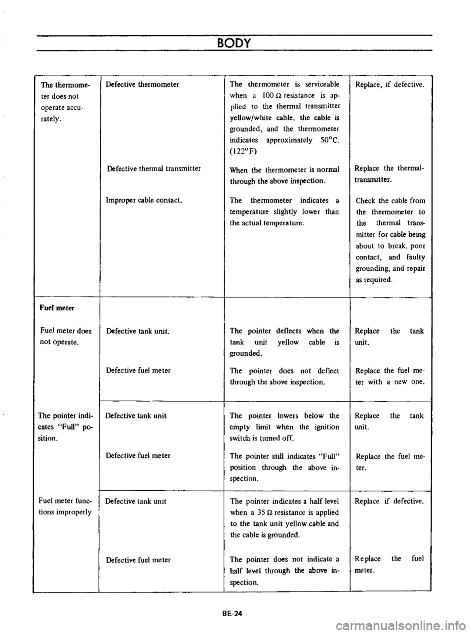
thermome
ter
does
not
operate
accu
rately
Fuel
meter
Fuel
meter
does
not
operate
Defective
thermometer
Defective
thermal
transmitter
Improper
cable
contact
Defective
tank
unit
Defective
fuel
meter
The
pointer
indi
Defective
tank
unit
cates
Full
po
sition
Fuel
meter
fune
tions
improperly
Defective
fuel
rneter
Defective
tank
unit
Defective
fuel
rneter
BODY
The
thermometer
is
serviceable
when
a
100
n
resistance
is
ap
plied
to
the
thermal
transmitter
yellow
white
cable
the
cable
is
grounded
and
the
thermorneter
indicates
approximately
500C
1220F
When
the
thermometer
is
normal
through
the
above
inspection
The
thermometer
indicates
a
temperature
slightly
lower
than
the
actual
temperature
The
poin
ter
tank
unit
grounded
deflects
yellow
when
the
cable
is
The
pointer
does
not
deflect
through
the
above
inspection
The
pointer
lowers
below
the
ernpty
limit
when
the
ignition
switch
is
turned
off
The
pointer
still
indicates
Full
position
through
the
above
in
spection
The
pointer
indicates
a
half
level
when
a
35
n
resistance
is
applied
to
the
tank
unit
yellow
cable
and
the
cable
is
grounded
The
pointer
does
not
indicate
a
half
level
through
the
above
in
spection
BE
24
Replace
if
defective
Replace
the
therrnal
transmitter
Check
the
cable
from
the
thermometer
to
the
thermal
trans
mitter
for
cable
being
about
to
break
poor
contact
and
faulty
grounding
and
repair
as
required
Replace
unit
the
tank
Replace
the
fuel
me
tee
with
a
new
one
Replace
the
tank
unit
Replace
the
fuel
me
ter
Replace
if
defective
Replace
the
fuel
meter
Page 271 of 513
BODY
I
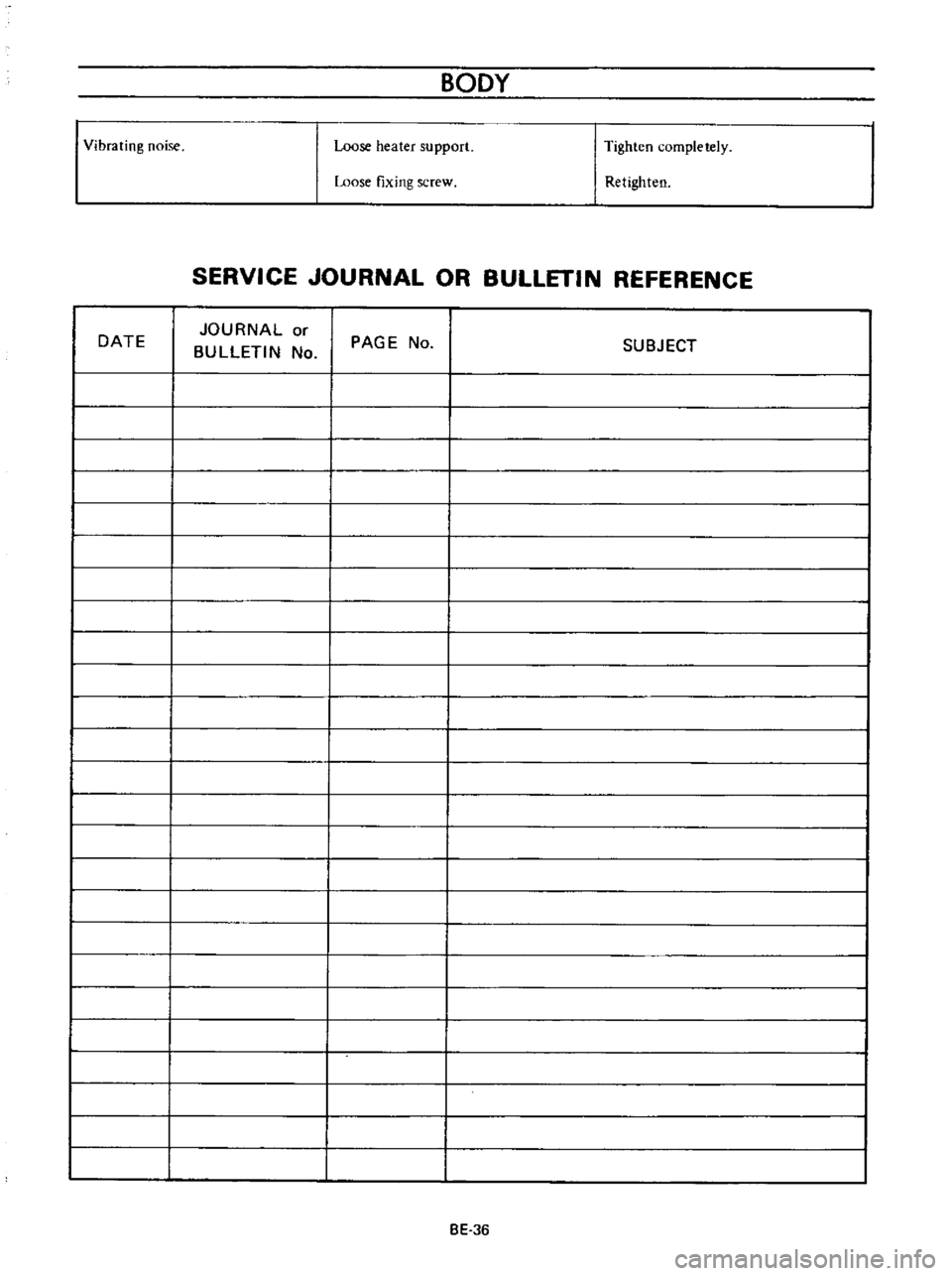
Vibrating
noise
Loose
heater
support
Tighten
completely
Loose
fixing
screw
Retighten
SERVICE
JOURNAL
OR
BULLETIN
REFERENCE
DATE
JOURNAL
or
BULLETIN
No
PAGE
No
SUBJECT
I
I
I
I
I
I
I
I
I
I
I
I
I
I
I
I
I
I
I
I
n
I
I
I
I
I
I
I
I
I
I
I
I
I
I
I
I
I
I
I
I
I
BE
36
Page 272 of 513
DATSUN
1200
MODEL
B
110
SERIES
lNISSAN
I
NISSAN
MOTOR
CO
LTD
TOKYO
JAPAN
SECTION
SE
SERVICE
EQUIPMENT
AI2
ENGINE
SPECIAL
SERVICE
TOOL
SE
I