1973 DATSUN B110 service
[x] Cancel search: servicePage 330 of 513

EMISSION
CONTROL
AND
TUNE
UP
SERVICE
DATA
AND
SPECIFICATIONS
Valve
clearance
Hot
Intake
Exhaust
mm
in
rom
in
rom
in
kg
lb
0
35
0
014
0
35
0
014
10
to
15
0
394
to
0
591
10
22
Fan
belt
tension
Tightening
torque
Cold
Cylinder
head
bolts
kg
m
ft
lb
1st
turn
2nd
turn
Re
tightening
torque
Hot
Manifold
nuts
Carburetor
nuts
4
0
to
4
5
29
to
33
5
5
to
6
0
40
to
43
6
0
to
6
5
43
to
47
0
9
to
I
4
6
5
to
10
0
5
to
1
0
3
6
to
7
2
1
5
to
2
0
II
to
14
Spark
plugs
Oil
capacity
of
engine
including
oil
ftIter
Maximum
L
US
gal
Imp
gal
L
US
gal
Imp
gal
3
3
U
14
2
3
Ii
Minimum
Water
capacity
of
cooling
system
Without
heater
L
US
gal
Imp
gal
With
heater
L
US
gal
Imp
gal
4
2
1
U
4
9
I
4
11
12
5
to
14
5
I78
to
206
350
Compression
pressure
at
rpm
kg
em
psi
Battery
specific
gravity
Permissible
value
Fully
charged
value
at
200C
680F
Frigid
climates
Tropical
climates
Other
elima
tes
Over
1
22
Over
1
18
Over
1
20
1
28
1
23
1
26
Ignition
timing
degree
Distributor
50
B
T
D
C
Condenser
capacity
mm
in
degrees
IlF
Micro
Farad
0
45
to
0
55
0
018
to
0
022
49
to
55
0
22
5
Point
gap
Dwell
angle
Condenser
insulation
resistance
Mil
Mega
ohms
ET
25
Page 339 of 513
ENGINE
Improper
air
fueled
mixtur
into
cylinder
walls
Check
the
fuel
system
Seizure
of
sliding
parts
Lkl
rease
of
oil
pressure
Previously
mentioned
Insufficient
clearances
Reassemble
with
the
designated
clear
ances
Overheat
Previously
mentioned
Improper
fuel
mixture
Check
the
fuel
system
SERViCE
JOURNAL
OR
6UU
ETIi
l
REFERENCE
DATE
JOURNAL
or
BULLETIN
No
PAGE
No
SUBJECT
ET
34
1t
Page 340 of 513
DATSUN
1200
MODEL
B
110
SERIES
L
NISSAN
I
NISSAN
MOTOR
CO
LTD
TOKYO
JAPAN
SECTION
EM
ENGINE
MECHANICAL
GENERAL
DESCRIPTION
ENGINE
DISASSEMBLY
INSPECTION
AND
REPAIR
ENGINE
ASSEMBLY
SERVICE
DATA
AND
SPECIFICATIONS
TROUBLE
DIAGNOSES
AND
CORRECTIONS
EM
I
EM
4
EM
8
EM
25
EM
33
EM
38
GI
Page 352 of 513
ENGINE
12
000
to
12
011
dia
0
4720
to
0
4724
I
t
r
1
1
1
ftlM
e
f
i1i
e
e
I
Standard
alve
guide
hole
diameter
UNIT
mm
in
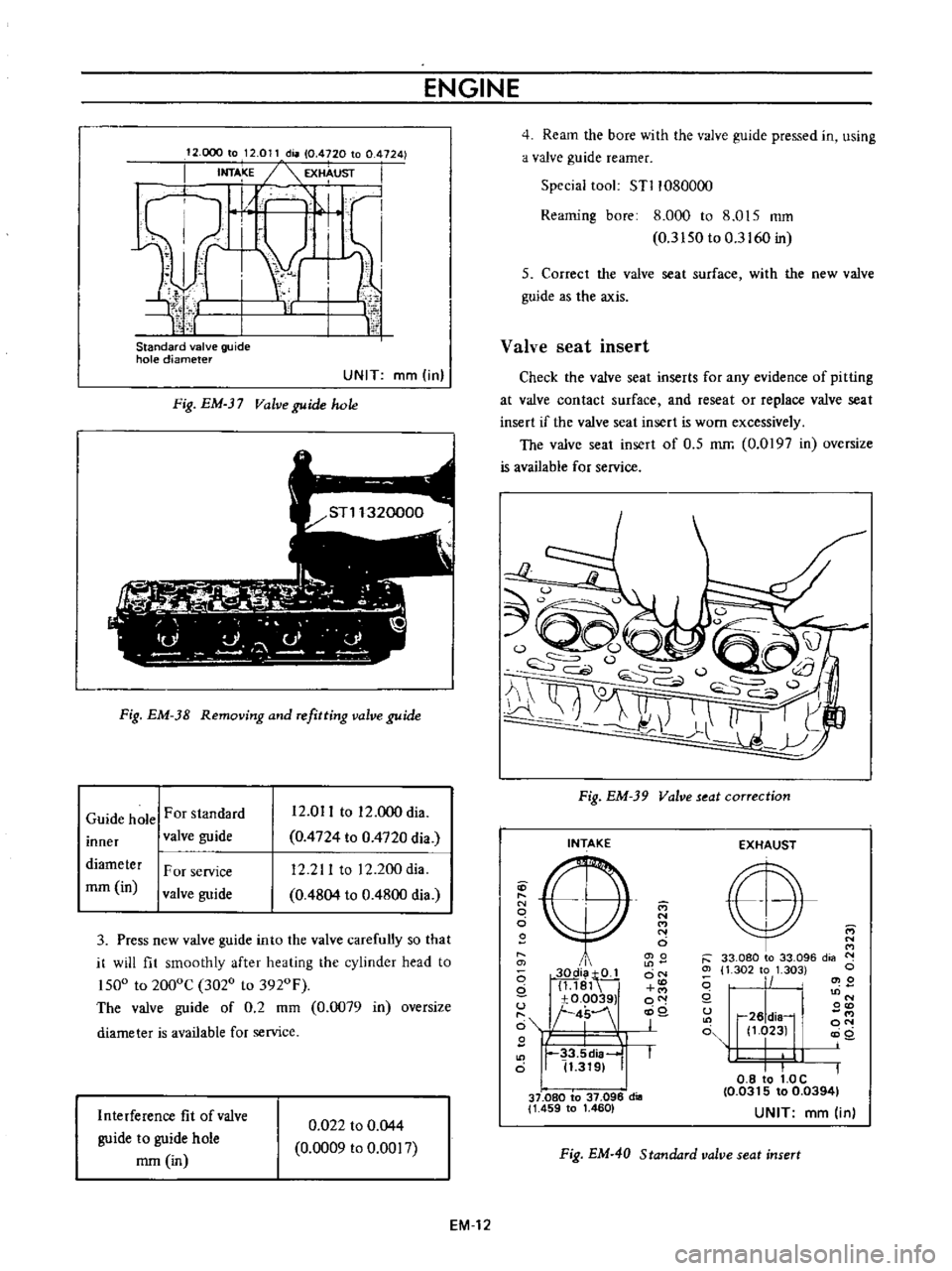
Fig
EM
Valve
guide
hole
Fig
EM
38
Removing
and
refitting
valve
guide
Guide
hole
For
standard
inner
valve
guide
12
011
to
12
000
dia
0
4724
to
0
4720
dia
12
211
to
12
200dia
0
4804
to
0
4800
dia
diameter
rom
in
F
or
service
valve
guide
3
Press
new
valve
guide
into
the
valve
carefully
so
that
it
will
fit
smoothly
after
heating
the
cylinder
head
to
ISOo
to
2000C
3020
to
3920F
The
valve
guide
of
0
2
mm
0
0079
in
oversize
diameter
is
available
for
service
Interference
fit
of
valve
guide
to
guide
hole
mm
in
0
022
to
0
044
0
0009
to
0
0017
4
Ream
the
bore
with
the
valve
guide
pressed
in
using
a
valve
guide
reamer
Special
tool
STl1080000
Reaming
bore
8
000
to
8
015
mm
0
3
ISO
to
0
3160
in
5
Correct
the
valve
seat
surface
with
the
new
valve
guide
as
the
axis
Valve
seat
insert
Check
the
valve
seat
inserts
for
any
evidence
of
pitting
at
valve
contact
surface
and
reseat
or
replace
valve
seat
insert
if
the
valve
seat
insert
is
worn
excessively
The
valve
seat
insert
of
O
S
mrr
0
0197
in
oversize
is
available
for
service
Fig
EM
39
Valve
seat
correction
INTAKE
D
N
o
o
i
i
o
2Q
Qi
tQJ
g
1
181
u
xO
00391
t
4
I
J
1
11
33
5d
a
o
I
11
3191
37
080
to
37
096
dill
1
459
to
1
460
M
N
M
N
o
0
0
ON
o
0
j
EXHAUST
E
r
33
080
to
33
096
dia
N
Ol
1
302
to
1
303
c
i
1
2
I
N
0
r26
dia
11
023
0
0
8
to
1
0C
10
0315
to
0
03941
UNIT
mm
in
Cl
Q
u
o
Fig
EM
40
Standard
valve
seat
insert
EM
12
Page 353 of 513
ENGINE
MECHANICAL
Cylinder
head
recess
diameter
For
standard
insert
Intake
Cylinder
head
recess
diameter
mm
in
For
service
insert
For
standard
insert
Exhaust
For
service
insert
Interference
fit
mm
in
Intake
Exhaust
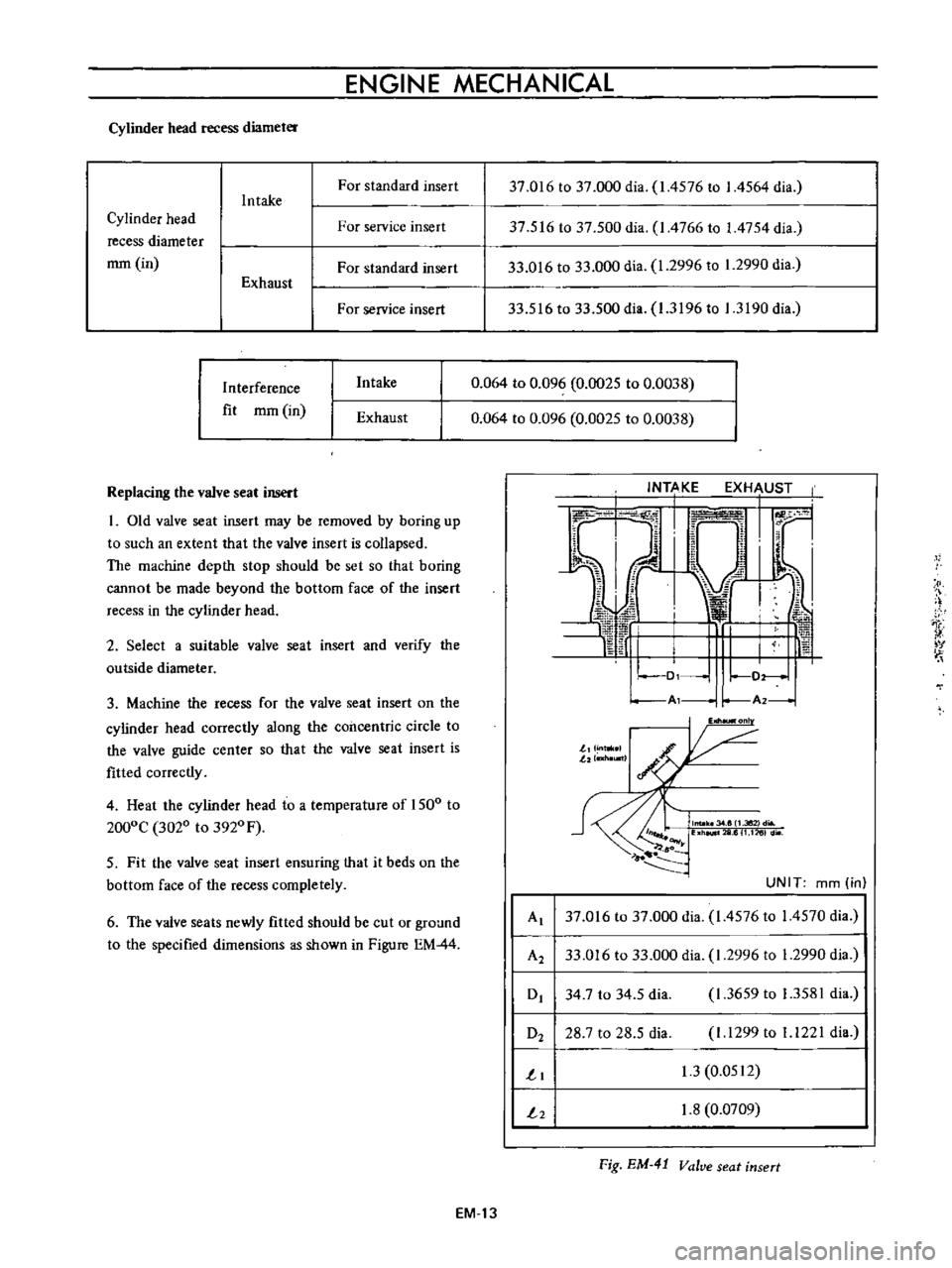
Replacing
the
valve
seat
insert
I
Old
valve
seat
insert
may
be
removed
by
boring
up
to
such
an
extent
that
the
valve
insert
is
collapsed
The
machine
depth
stop
should
be
set
so
that
boring
cannot
be
made
beyond
the
bottom
face
of
the
insert
recess
in
the
cylinder
head
2
Select
a
suitable
valve
seat
insert
and
verify
the
outside
diameter
3
Machine
the
recess
for
the
valve
seat
insert
on
the
cylinder
head
correctly
along
the
concentric
circle
to
the
valve
guide
center
so
that
the
valve
seat
insert
is
fitted
correctly
4
Heat
the
cylinder
head
to
a
temperature
of
1500
to
2000C
3020
to
3920
F
5
Fit
the
valve
seat
insert
ensuring
that
it
beds
on
the
bottom
face
of
the
recess
completely
6
The
valve
seats
newly
fitted
should
be
cut
or
ground
to
the
specified
dimensions
as
shown
in
Figure
EM
44
37
016
to
37
000
dia
1
4576
to
I
4564
dia
37
516
to
37
500
dia
I
4766
to
1
4754
dia
33
016
to
33
000
dia
1
2996
to
1
2990
dia
33
516
to
33
500
dia
1
3196
to
1
3190
dia
0
064
to
0
096
0
0025
to
0
0038
0
064
to
0
096
0
0025
to
0
0038
I
t
v
Al
r
A2
I
onl
J
J
n
llI
lltl
I
G
llW
6
UNIT
mm
in
Al
37
016
to
37
000
dia
1
4576
to
14570
dia
A2
33
016
to
33
000
dia
1
2996
to
1
2990
dia
0
34
7
to
34
5
dia
1
3659
to
1
3581
dia
O2
28
7
to
28
5
dia
I
1299
to
1
1221
dia
1
1
3
0
0512
2
1
8
0
0709
Fig
EM
41
Valve
seat
insert
EM
13
Page 357 of 513
ENGINE
MECHANICAL
5
M
co
El
co
I
ED
I
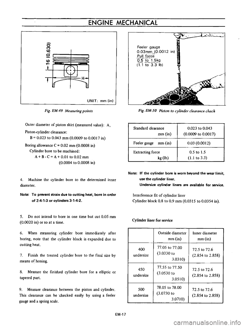
UNIT
mm
in
Fig
EM
49
Measuring
points
Outer
diameter
of
piston
skirt
measured
value
A
Piston
eylinder
clearance
B
0
023
to
0
043
mm
0
0009
to
0
0017
in
Boring
allowance
C
0
02
rom
0
0008
in
Cylinder
bore
to
be
machined
A
B
C
A
om
to
0
02
mm
0
0004
to
0
0008
in
4
Machine
the
cylinder
bore
to
the
determined
inner
diameter
Note
To
prevent
strain
due
to
cutting
heat
bore
in
order
of
2
4
3
or
cylinders
3
4
2
5
Do
not
intend
to
bore
in
one
time
but
cut
0
05
rom
0
0020
in
or
so
at
a
time
6
When
measuring
cylinder
bore
immediately
after
boring
note
that
the
cylinder
block
is
expanded
due
to
cutting
heat
7
Finish
the
treated
cylinder
bore
to
the
final
size
by
means
of
honing
8
Measure
the
finished
cylinder
bore
for
a
elliptic
or
tapered
part
9
Measure
clearance
between
the
piston
and
cylinder
This
clearance
can
be
checked
easily
by
using
a
feeler
gauge
and
a
spring
scale
EM
17
Feeler
gauge
0
03mm
0
0012
in
Pull
force
o
5to
5kg
11
to3
3
lb
i
Fig
EM
50
Piston
to
cylinder
clearance
check
Standard
clearance
rom
in
0
023
to
0
043
0
0009
to
0
0017
0
03
0
0012
Feeler
gauge
mm
in
Extracting
force
kg
Ib
0
5
to
1
5
1
1
to
3
3
Note
If
the
cylinder
bore
is
worn
beyond
the
wear
limit
use
the
cylinder
liner
Undersize
cylinder
liners
are
available
for
service
Interference
fit
of
cylinder
liner
Cylinder
block
0
8
to
0
9
mm
0
0315
to
0
0354
in
Cylinder
liner
for
service
400
undersize
Outside
diameter
mm
in
77
05
to
77
00
3
0330
to
3
0310
77
55
to
77
50
3
0530
to
3
0510
78
05
to
78
00
3
0730
to
3
0710
72
5
to
72
6
2
854
to
2
858
Inner
diameter
mm
in
72
5
to
72
6
2
854
to
2
858
450
undersize
72
5
to
72
6
2
854
to
2
858
500
undersize
Page 359 of 513
ENGINE
MECHANICAL
Note
8
When
the
piston
ring
only
is
to
be
replaced
without
the
cylinder
bore
being
corrected
measure
gap
at
the
bottom
of
the
cylinder
where
the
wear
is
minor
b
Oversize
piston
rings
are
available
for
service
50
100
150
oversize
4
Measure
the
piston
pin
hole
in
relation
to
the
outer
diameter
of
the
pin
If
wear
exceeds
the
limit
replace
such
piston
pin
together
with
the
piston
on
which
it
is
installed
Piston
pin
diameter
mm
in
17447
to
17452
0
6869
to
0
6871
65
23
to
65
48
2
5681
to
5
779
Piston
pin
length
mm
in
Piston
pin
hole
dia
meter
mm
in
17460
to
17453
0
6874
to
0
6871
5
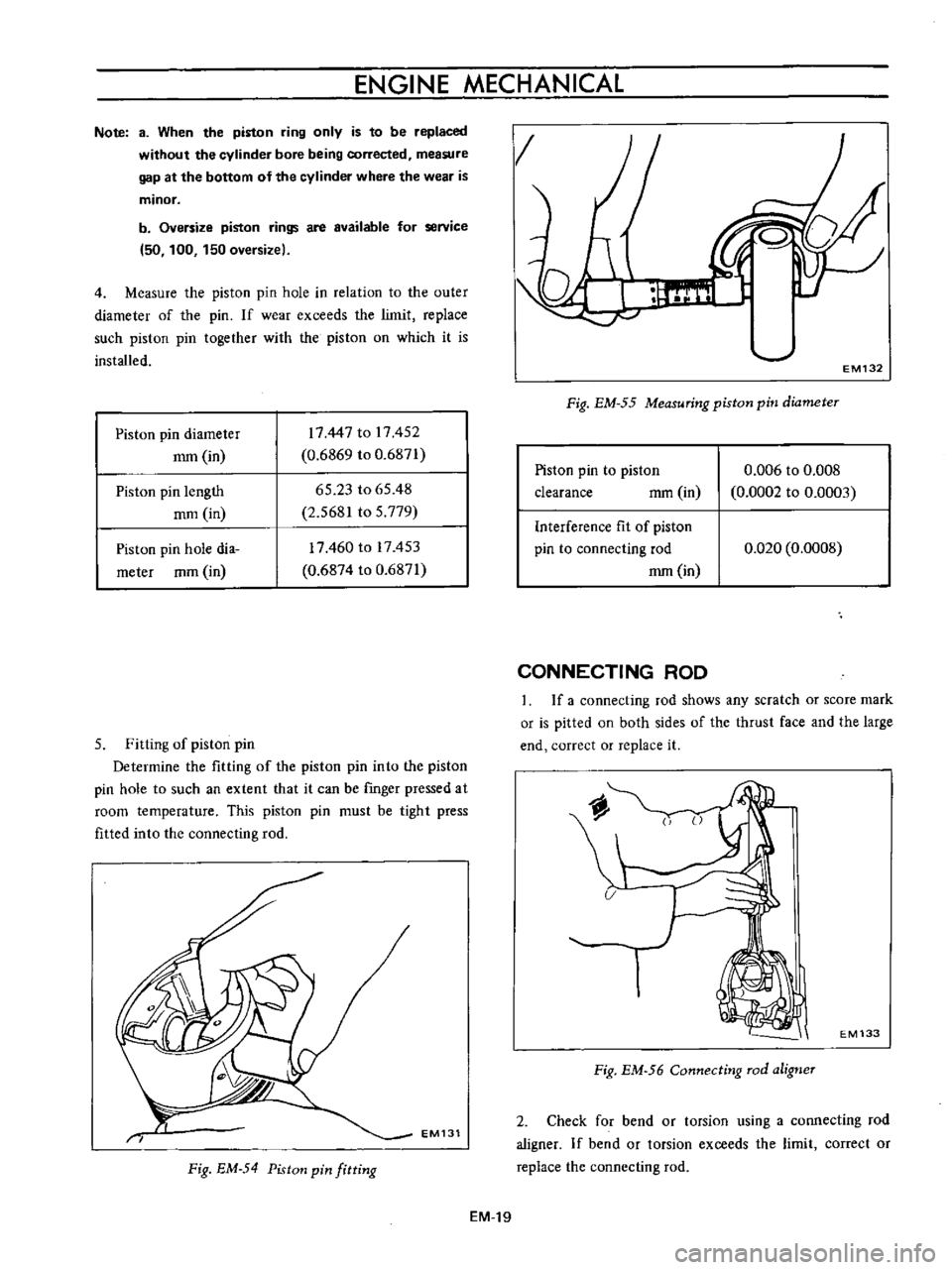
Fitting
of
piston
pin
Determine
the
fitting
of
the
piston
pin
into
the
piston
pin
hole
to
such
an
extent
that
it
can
be
rmger
pressed
at
room
temperature
This
piston
pin
must
be
tight
press
fitted
into
the
connecting
rod
EM131
Fig
EM
54
Piston
pin
fitting
EM
19
g
1
EM132
Fig
EM
55
Measuring
piston
pin
diameter
Piston
pin
to
piston
clearance
mm
in
0
006
to
0
008
0
0002
to
0
0003
Interference
fit
of
piston
pin
to
connecting
rod
mm
in
0
020
0
0008
CONNECTING
ROD
If
a
connecting
rod
shows
any
scratch
or
score
mark
or
is
pitted
on
both
sides
of
the
thrust
face
and
the
large
end
correct
or
replace
it
EM133
Fig
EM
56
Connecting
rod
aligner
2
Check
for
bend
or
torsion
using
a
connecting
rod
aligner
If
bend
or
torsion
exceeds
the
limit
correct
or
replace
the
connecting
rod
Page 363 of 513
ENGINE
MECHANICAL
3
Ascertain
that
the
clearance
is
within
double
the
figure
listed
below
If
it
is
not
replace
the
bearing
4
Handle
the
connecting
rod
bearing
in
the
same
manner
Connecting
rod
cap
tightening
torque
3
2
to
3
8
kg
m
23
to
28
ft
lb
Bearing
crush
All
main
bearing
mm
in
o
to
0
03
0
to
0
0012
All
connecting
rod
bearing
mm
in
0
Ql5
to
0
040
0
0006
to
0
0016
Main
bearing
undersize
Bearing
size
Bearing
top
Crank
journal
1
100
thickness
mm
in
diameter
mm
in
STD
1
835
to
1
822
49
951
to
49
964
0
0722
to
0
0717
1
9666
to
1
9671
25
1
960
to
1
947
49701
to
49
714
undersize
0
0772
to
0
0767
1
9567
to
1
9572
50
2
085
to
2
072
49451
to
49
464
undersize
0
0821
to
0
0816
1
9469
to
1
9474
75
2
210
to
2
197
49
201
to
49
214
undersize
0
0870
to
0
0865
1
9370
to
1
9376
100
2
335
to
2
322
48
951
to
48
964
undersize
0
0919
to
0
0914
1
9272
to
1
9277
Connecting
rod
bearing
undersize
Bearing
top
Crank
pin
Bearing
size
thickness
mm
in
diameter
mm
in
1
500
to
1
508
44
961
to
44
974
0
0591
to
0
0594
1
8489
to
I
7706
8
1
540
to
1
548
44
881
to
44
894
undersize
0
0606
to
0
0609
1
7670
to
I
7675
STD
12
1
560
to
1
568
44
841
to
44
854
undersize
0
0614
to
0
0617
I
7654
to
I
7659
25
1
625
to
1
633
44
711
to
44
724
undersize
0
0640
to
0
0643
1
7603
to
I
7608
50
I
750
to
1
758
44
461
to
44
474
undersize
0
0689
to
0
0692
1
7504
to
I
7509
75
1
875
to
1
883
44
211
to
44
224
undersize
0
0738
to
0
0741
1
7406
to
I
7411
100
2
000
to
2
008
43
961
to
43
974
undersize
0
0787
to
0
0791
1
7307
to
I
7313
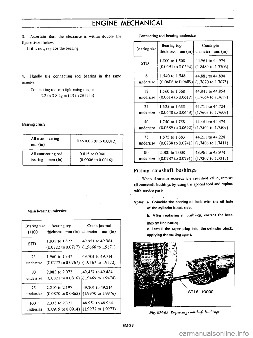
Fitting
camshaft
bushings
When
clearance
exceeds
the
specified
value
remove
all
camshaft
bushings
by
using
the
special
tool
and
replace
with
service
parts
Notes
3
Coincide
the
bearing
oil
hole
with
the
oil
hole
of
the
cylinder
block
side
b
After
replacing
all
bushings
correct
the
bear
ings
by
line
boring
c
I
nstall
the
taper
plug
into
the
cylinder
block
applying
the
sealing
agent
Fig
EM
65
Replacing
camshaft
bushings
EM
23