1973 DATSUN B110 service
[x] Cancel search: servicePage 373 of 513

ENGINE
MECHANICAL
SERVICE
DATA
AND
SPECIFICATIONS
GENERAL
SPECIFICATION
Cylinder
arrangement
4
in
line
Displacement
cc
cu
in
mm
in
1
171
71
5
73
x
70
2
874
x
2
756
Bore
and
stroke
Valve
arrangemen
t
Over
head
valve
Firing
order
I
3
4
2
Engine
idle
rpm
800
Manual
transmission
650in
D
Automatic
transmission
Compression
ratio
8
5
Oil
pressure
Hot
at
2
000
rpm
kgfcm2
Ibfsq
in
3
0
to
3
5
43
to
50
TIGHTENING
TORQUE
Unit
kg
m
ft
lb
Cylinder
head
bolts
Flywheel
bolts
5
5
to
6
0
40
to
43
3
2
to
3
8
23
to
28
6
5
to
7
5
47
to
54
5
0
to
6
0
36
to
43
4
0
to
4
8
29
to
35
0
4
to
0
6
2
9
to
4
3
l
l
to
I
7
8
0
to
12
0
9
to
I
4
6
5
to
10
15
to
16
108
to
116
Connecting
rod
nuts
Main
bearing
cap
bolts
Camshaft
gear
bolts
Oil
pan
bolts
Oil
pump
bolts
Oil
strainer
bolts
Crank
pulley
bolts
EM
33
Page 376 of 513
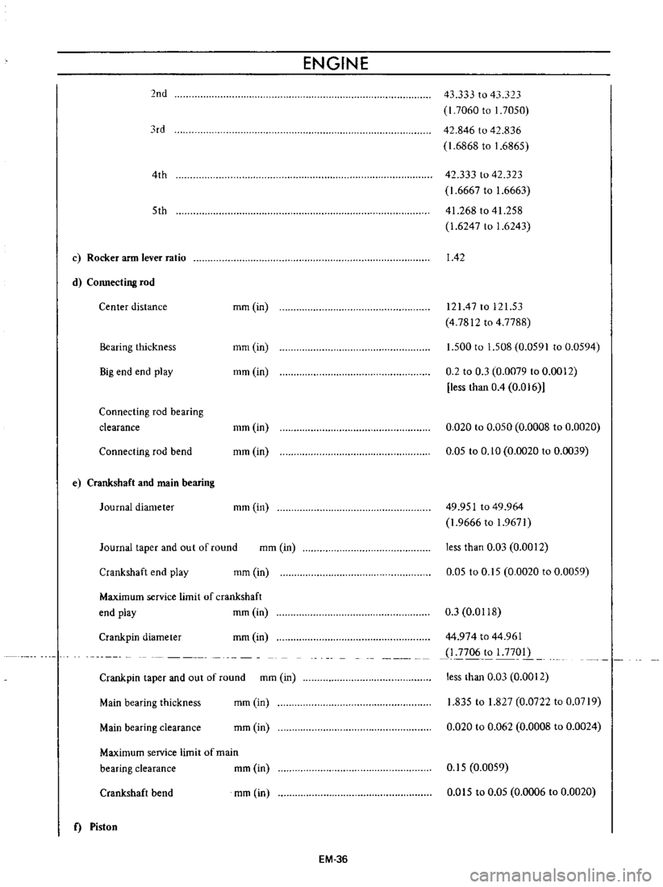
2nd
lrd
4th
5th
c
Rocker
arm
lever
ratio
d
Connecting
rod
Center
distance
Bearing
thickness
Big
end
end
play
Connecting
rod
bearing
clearance
Connecting
rod
bend
e
Crankshaft
and
main
bearing
Journal
diameter
Journal
taper
and
out
of
round
Crankshaft
end
play
mm
in
mm
in
mm
in
mm
in
mm
in
mm
in
mm
in
mm
in
Maximum
service
limit
of
crankshaft
mm
in
end
play
Crank
pin
diameter
mm
in
Main
bearing
thickness
Crank
pin
taper
and
out
of
round
mm
in
mm
in
Main
bearing
clearance
mm
in
Maximum
seIVice
limit
of
main
bearing
clearance
mm
in
Crankshaft
bend
f
Piston
mm
in
ENGINE
43
333
to
43
323
l
7060
to
I
7050
42
846
to
42
836
1
6868
to
1
6865
42
333
to
42
323
1
6667
to
1
6663
41
268
to
41
258
1
6247
to
1
6243
142
12147
to
121
53
4
7812
to
4
7788
1
500
to
1
508
0
0591
to
0
0594
0
2
to
0
3
0
0079
to
0
0012
less
than
0
4
0
016
0
020
to
0
050
0
0008
to
0
0020
0
05
to
0
10
0
0020
to
0
0039
49
951
to
49
964
1
9666
to
1
9671
less
than
0
03
0
0012
0
05
to
0
15
0
0020
to
0
0059
0
3
0
0118
44
974
to
44
961
1
2706
1
177012
less
than
0
03
0
0012
1
835
to
1
827
0
0722
to
0
0719
0
020
to
0
062
0
0008
to
0
0024
0
15
0
0059
0
Gl5
to
0
05
0
0006
to
0
0020
EM
36
Page 390 of 513
ENGINE
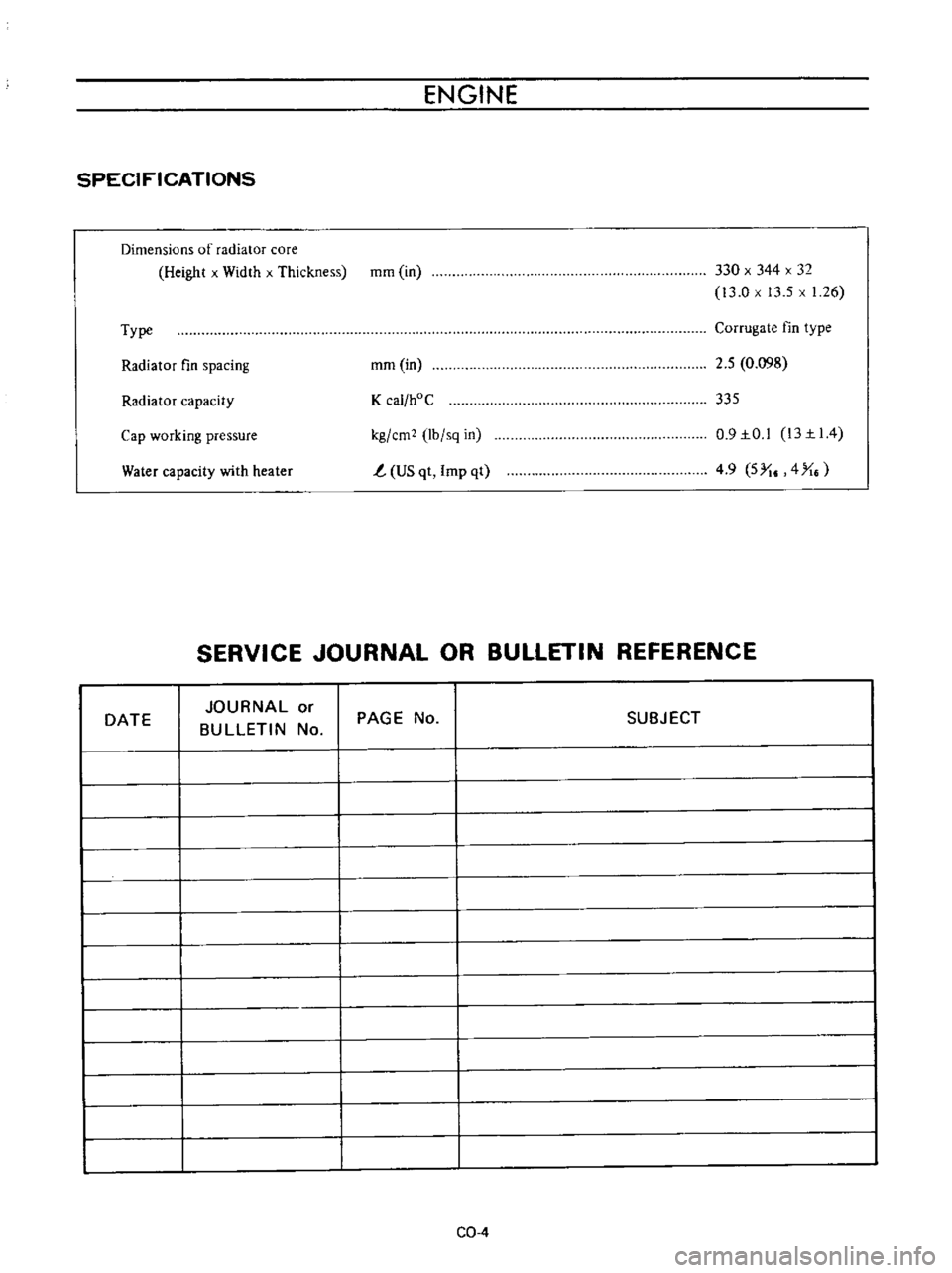
SPECIFICATIONS
Dimensions
of
radiator
core
Height
x
Width
x
Thickness
mm
in
330
x
344
x
32
13
0
x
13
5
x
1
26
Type
Corrugate
fin
type
Radiator
fin
spacing
mm
in
2
5
0
098
Radiator
capacity
K
cal
hoC
335
Water
capacity
with
heater
kg
em
lb
sq
in
t
US
qt
Imp
qt
0
9IO
l
13II4
4
9
5
I
4
X
Cap
working
pressure
SERVICE
JOURNAL
OR
BULLETIN
REFERENCE
DATE
JOURNAL
or
BULLETIN
No
PAGE
No
SUBJECT
CQ
4
Page 396 of 513

FUEl
SYSTEM
FUEL
STRAINER
DESCRIPTION
The
fuel
strainer
is
of
a
cartridge
type
It
uses
paper
element
as
strainer
element
which
can
be
checked
for
condition
from
outside
This
strainer
cannot
be
cleaned
Replace
the
strainer
at
the
specified
service
interval
or
if
it
becomes
clogged
or
restricted
REMOVAL
Disconnect
inlet
and
outlet
fuel
lines
from
fuel
strainer
and
remove
fuel
strainer
Note
Before
disconnecting
fuel
lines
use
a
container
to
receive
the
remaining
fuel
in
lines
r
@
I
I
Il
QY
I
I
I
elementl
3
Cover
@
EF005
Fig
EF
10
Sectional
view
of
caTtridge
type
fuel
stTaineT
FUEL
PUMP
CONTENTS
DESCRIPTION
FUEL
PUMP
TESTING
Static
pressure
test
Capacity
test
EF
5
EF
6
EF
6
EF
6
DESCRIPTION
The
fuel
pump
transfers
gasoline
from
the
tank
to
the
carburetor
in
sufficient
quantity
to
meet
engine
require
ments
at
any
speed
or
load
The
fuel
pump
is
of
the
diaphragm
type
REMOVAL
AND
DISASSEMBLY
INSPECTION
ASSEMBLY
EF
7
EF
B
EF
B
The
fuel
pump
consists
of
a
body
rocker
arm
and
link
assembly
fuel
diaphragm
fuel
diaphragm
spring
seal
inlet
and
outlet
valves
The
fuel
diaphragm
consists
of
specially
treated
rubber
which
is
not
affected
by
gasoline
held
together
with
two
metal
discs
and
a
pull
rod
EF
5
Page 399 of 513
ENGINE
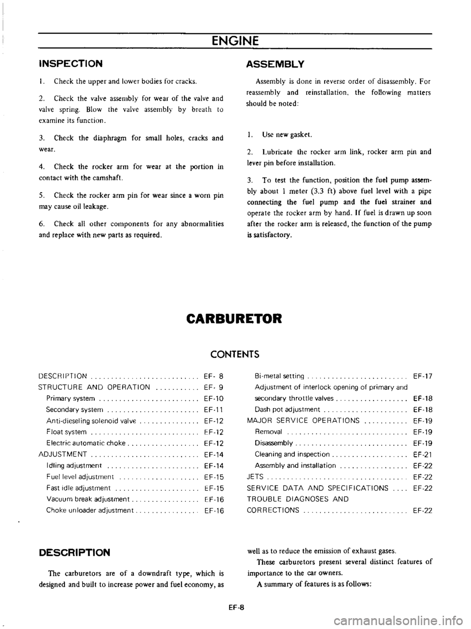
INSPECTION
Check
the
upper
and
lower
bodies
for
cracks
2
Check
the
valve
assembly
for
wear
of
the
valve
and
valve
spring
Blow
the
valve
assembly
by
breath
to
examine
its
function
3
Check
the
diaphragm
for
small
holes
cracks
and
wear
4
Check
the
rocker
arm
for
wear
at
the
portion
in
contact
with
the
camshaft
5
Check
the
rocker
arm
pin
for
wear
since
a
worn
pin
may
cause
oil
leakage
6
Check
all
other
components
for
any
abnormalities
and
replace
with
new
parts
as
required
ASSEMBLY
Assembly
is
done
in
reverse
order
of
disassembly
For
reassembly
and
reinstallation
the
following
matters
should
be
noted
Use
new
gasket
2
Lubricate
the
rocker
arm
link
rocker
arm
pin
and
lever
pin
before
installation
3
To
test
the
function
position
the
fuel
pump
assem
bly
about
I
meter
3
3
ft
above
fuel
level
with
a
pipe
connecting
the
fuel
pump
and
the
fuel
strainer
and
operate
the
rocker
afm
by
hand
If
fuel
is
drawn
up
soon
after
the
rocker
arm
is
released
the
function
of
the
pump
is
satisfactory
CARBURETOR
CONTENTS
DESCRIPTION
STRUCTURE
AND
OPERATION
EF
8
EF
9
EF
10
EF
11
EF
12
EF
12
EF
12
EF
14
EF
14
EF
15
EF
15
EF
16
EF
16
Primary
system
Secondary
system
Anti
dieseling
solenoid
valve
Float
system
Electric
automatic
choke
ADJUSTMENT
Idling
adjustment
Fuel
level
adjustment
Fast
idle
adjustment
Vacuum
break
adjustment
Choke
un
loader
adjustment
DESCRIPTION
The
carburetors
are
of
a
downdraft
type
which
is
designed
and
built
to
increase
power
and
fuel
economy
as
Bi
metal
setting
Adjustment
of
interlock
opening
of
primary
and
secondary
throttle
valves
Dash
pot
adjustment
MAJOR
SERVICE
OPERATIONS
Removal
Disassembly
Cleaning
and
inspection
Assembly
and
installation
JETS
SERVICE
DATA
AND
SPECIFICATIONS
TROUBLE
DIAGNOSES
AND
CORRECTIONS
EF
17
EF
18
EF
18
EF
19
EF
19
EF
19
EF
21
EF
22
EF
22
EF
22
EF
22
well
as
to
reduce
the
emission
of
exhaust
gases
These
carburetors
present
several
distinct
features
of
importance
to
the
car
owners
A
summary
of
features
is
as
follows
EF
8
Page 410 of 513
FUEl
SYSTEM
MA
JOR
SERVICE
OPERATIONS
A
completely
adjusted
and
serviced
carburetor
will
provide
the
engine
with
proper
mixture
at
all
speeds
Periodical
overhauling
which
cleans
all
components
and
passages
will
recover
the
originally
designed
performance
producing
the
engine
with
proper
gasoline
and
air
ratio
at
all
speeds
Passages
and
holes
of
the
carburetor
must
be
cleaned
carefully
Use
only
carburetor
solvent
and
com
pressed
air
to
clean
aU
passages
and
discharge
holes
Never
use
wire
or
other
pointed
tool
otherwise
accurately
calibrated
carburetor
will
be
affected
Removal
Remove
the
air
cleaner
2
Disconnect
the
fuel
line
vacuum
line
automatic
choke
harness
and
anti
dieseling
solenoid
harness
from
carburetor
3
Remove
the
throttle
lever
4
Remove
four
nuts
and
washers
retaining
the
carbuTe
tor
to
the
manifold
if
necessary
5
Lift
the
carburetor
and
remove
from
the
manifold
6
Remove
and
discard
the
gasket
used
between
the
carburetor
and
manifold
Disassembly
The
main
jets
and
needle
valves
on
both
primary
and
secondary
sides
are
accessible
from
outside
of
the
carbure
tor
for
disassembly
2
Remove
throttle
return
spring
3
Remove
pump
lever
shaft
take
out
pump
lever
and
pump
connecting
rod
4
Remove
rubber
pipe
from
choke
piston
5
Loosen
off
bolts
securing
servo
diaphragm
in
posi
tion
take
out
diaphragm
6
Back
off
total
of
five
bolts
which
hold
choke
in
position
and
remove
rods
of
starter
system
take
out
choke
chamber
In
removing
chamber
exercise
care
to
avoid
damaging
float
EF
19
ilia
Fig
EF
32
Removing
choke
dwmherand
seroo
diaphragm
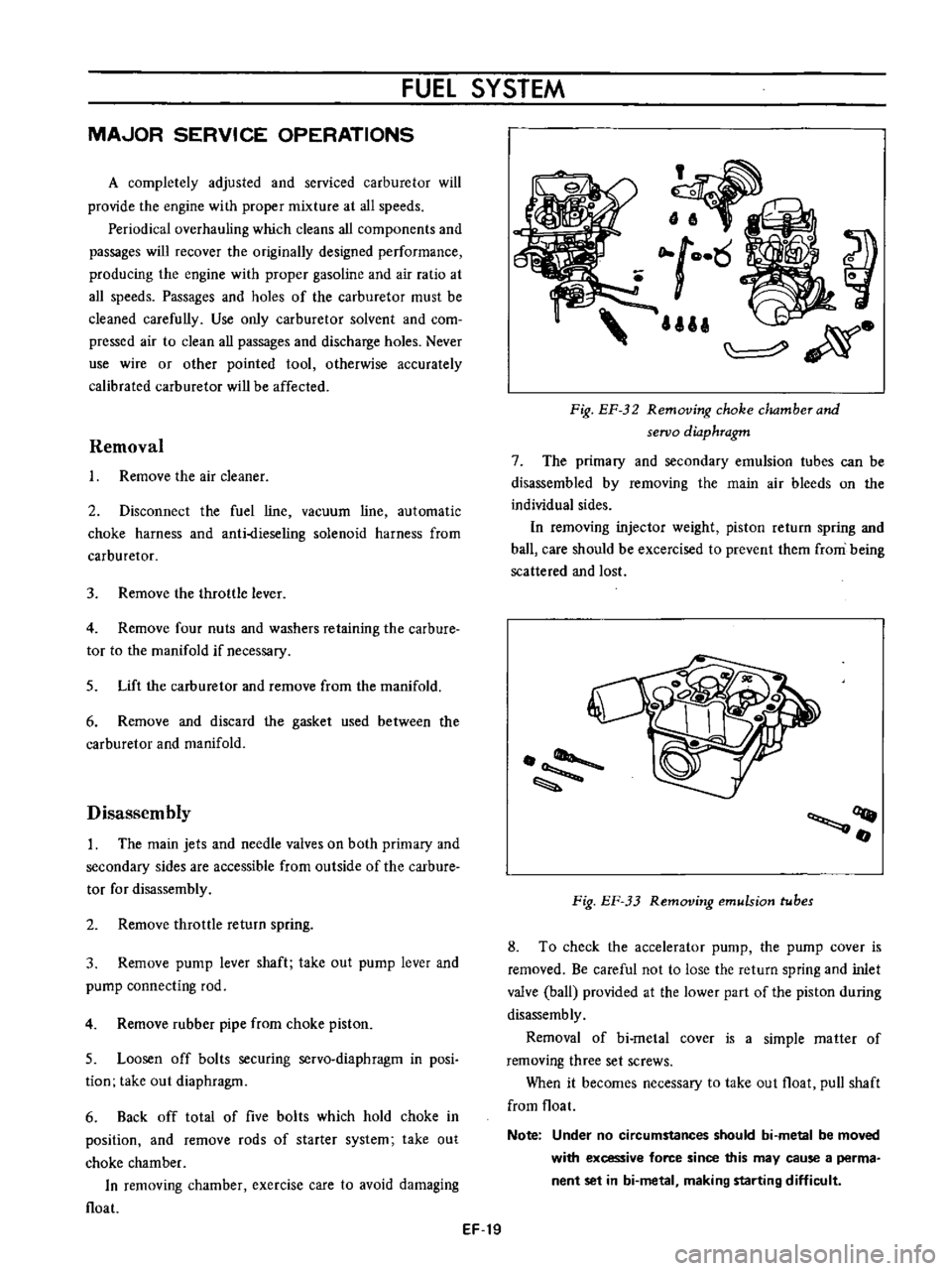
7
The
primary
and
secondary
emulsion
tubes
can
be
disassembled
by
removing
the
main
air
bleeds
on
the
individual
sides
In
removing
injector
weight
piston
return
spring
and
ball
care
should
be
excercised
to
prevent
them
from
being
scattered
and
lost
OQ
fI
Fig
EF
33
Removing
emulsion
tubes
8
To
check
the
accelerator
pump
the
pump
cover
is
removed
Be
careful
not
to
lose
the
return
spring
and
inlet
valve
ball
provided
at
the
lower
part
of
the
piston
during
disassemb
ly
Removal
of
bi
metal
cover
is
a
simple
matter
of
removing
three
set
screws
When
it
becomes
necessary
to
take
out
float
pull
shaft
from
float
Note
Under
no
circumstances
should
bi
metal
be
moved
with
excessive
force
since
this
may
cause
a
perma
nent
set
in
bi
metal
making
starting
difficult
Page 412 of 513
FUEL
SYSTEM
5
Check
venturi
clusters
for
loose
or
worn
parts
If
damage
or
looseness
exists
replace
cluster
assembly
6
Check
the
linkage
for
operating
condition
7
Inspect
the
operation
of
accelerating
pump
Pour
gasoline
into
the
float
chamber
and
operate
the
throttle
lever
Check
condition
of
gasoline
injection
from
the
accelerating
nozzle
Assembly
and
instalIetion
Assemble
and
install
the
carburetor
in
reverse
sequence
of
disassembly
and
removal
Replace
the
gaskets
if
necessary
When
disassembling
and
reassembling
the
interlock
link
and
related
components
be
careful
not
to
bend
or
deform
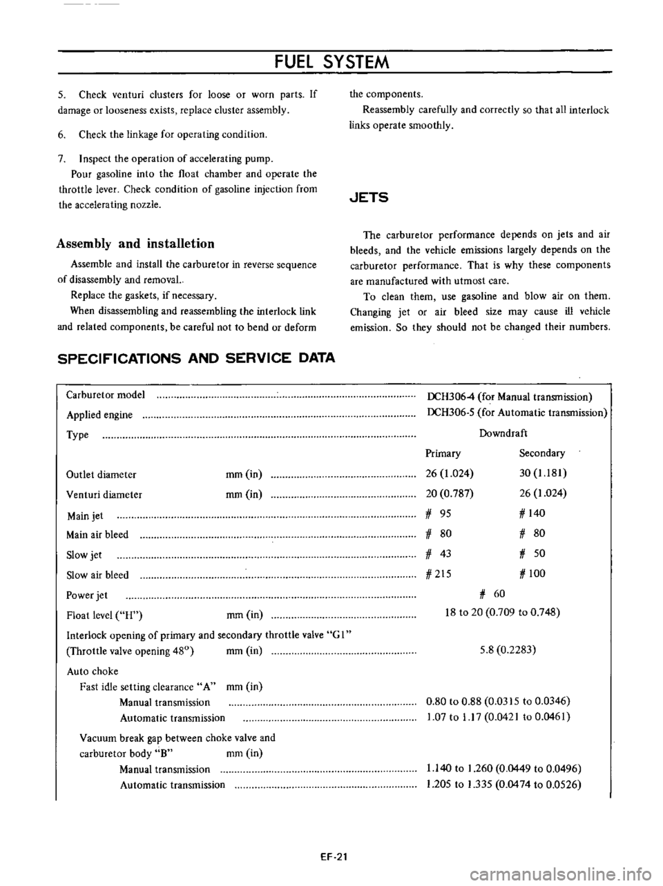
SPECIFICATIONS
AND
SERVICE
DATA
Carburetor
model
Applied
engine
Type
Outlet
diameter
mm
in
rom
in
Venturi
diameter
Main
jet
Main
air
bleed
Slow
jet
Slow
air
bleed
Power
jet
Float
level
H
rom
in
Interlock
opening
of
primary
and
secondary
throttle
valve
G
I
Throttle
valve
opening
480
mm
in
Auto
choke
Fast
idle
setting
clearance
A
mm
in
Manual
transmission
Automatic
transmission
Vacuum
break
gap
between
choke
valve
and
carburetor
body
8
mm
in
Manual
transmission
Automatic
transmission
EF
21
the
components
Reassembly
carefully
and
correctly
so
that
all
interlock
links
operate
smoothly
JETS
The
carburetor
performance
depends
on
jets
and
air
bleeds
and
the
vehicle
emissions
largely
depends
on
the
carburetor
performance
That
is
why
these
components
are
manufactured
with
utmost
care
To
clean
them
use
gasoline
and
blow
air
on
them
Changing
jet
or
air
bleed
size
may
cause
ill
vehicle
emission
So
they
should
not
be
changed
their
numbers
DCH3064
for
Manual
transmission
DCH306
5
for
Automatic
transmission
Downdraft
Primary
Secondary
26
1
024
30
1
181
20
0
787
26
1
024
1
95
1
140
1
80
1
80
1
43
1
50
1
215
1
100
1
60
18
to
20
0
709
to
0
748
5
8
0
2283
0
80
to
0
88
0
0315
to
0
0346
1
07
to
1
17
0
0421
to
0
0461
1
140
to
1
260
0
0449
to
0
0496
1
205
to
1
335
0
0474
to
0
0526
Page 419 of 513
DATE
ENGINE
SERVICE
JOURNAL
OR
BULLETIN
REFERENCE
JOURNAL
or
BULLETIN
No
PAGE
No
SUBJECT
EF
28