1973 DATSUN B110 service
[x] Cancel search: servicePage 423 of 513
ENGINE
ElECTRICAL
SYSTEM
5
If
the
specific
gravity
is
above
1
260
200C
or
680F
after
charging
adjust
it
by
adding
distilled
water
6
Keep
any
open
flame
away
from
the
place
where
the
battery
is
being
charged
7
Replace
vent
plugs
and
clean
the
upper
face
of
the
battery
after
charging
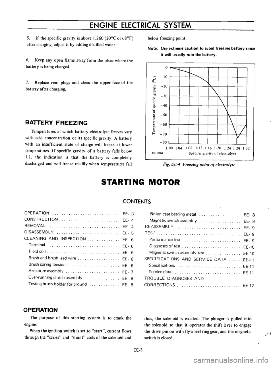
BATTERY
FREEZING
Temperatures
at
which
battery
electrolyte
freezes
vary
with
acid
concentration
or
its
specific
gravity
A
battery
with
an
insufficient
state
of
charge
will
freeze
at
lower
temperatures
If
specific
gravity
of
a
battery
falls
below
I
I
the
indication
is
that
the
battery
is
completely
discharged
and
will
freeze
readily
when
temperatures
fall
below
freezing
point
Note
Use
extreme
caution
to
avoid
freezing
battery
since
it
will
usually
ruin
the
battery
o
I
I
1
G
10
I
1
o
i
20
I
u
30
I
I
0
40
I
0
SO
I
60
0
I
E
f
o
70
I
80
1
00
1
04
1
08
I
12
1
16
20
24
1
28
1
32
E
E004
Specific
gravity
of
electrolyte
Fig
EE
4
FTeezing
point
of
electrolyte
STARTI
NG
MOTOR
CONTENTS
OPERATION
CONSTRUCTION
REMOVAL
DISASSEMBL
Y
CLEANING
AND
INSPECTION
Terminal
Field
coil
Brush
and
brush
lead
wire
Brush
spring
tension
Armature
assembly
Over
running
clutch
assembly
Testing
brush
holder
for
ground
EE
3
EE
4
EE
4
EE
5
EE
6
EE
6
EE
6
EE
6
EE
6
EE
7
EE
8
EE
8
OPERATION
The
purpose
of
this
starting
system
is
to
crank
the
engine
When
the
ignition
switch
is
set
to
start
current
flows
through
the
series
and
shunt
coils
of
the
solenoid
and
Pinion
case
bearing
metal
Magnetic
switch
assembly
REASSEMBL
Y
TESr
Performance
test
Diagnoses
of
test
Magnetic
switch
assembly
test
SPECIFICATIONS
AND
SERVICE
DATA
Specifications
Service
data
TROU8LE
DIAGNOSES
AND
CORRECTIONS
EE
8
EE
8
EE
9
EE
9
EE
g
EE
10
EE
10
EE
11
EE
11
EE
11
EE
12
thus
the
solenoid
is
excited
The
plunger
is
pulled
into
the
solenoid
so
that
it
operates
the
shift
lever
to
engage
the
drive
pinion
with
flywheel
ring
gear
and
the
magnetic
switch
is
closed
EE
3
Page 429 of 513
ENGINE
ElECTRICAL
SYSTEM
shunt
coil
is
satisfactory
if
the
plunger
is
attracted
continuously
s
SERIES
COIL
S
SHUNT
COIL
Fig
EE
21
Inspecting
series
and
shunt
coils
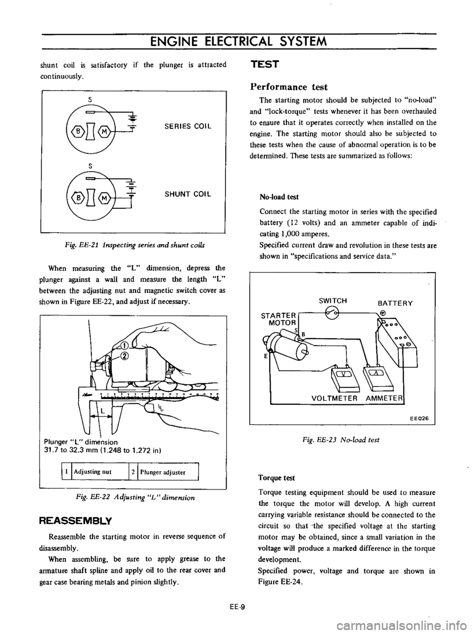
When
measuring
the
L
dimension
depress
the
plunger
against
a
wall
and
measure
the
length
L
between
the
adjusting
nut
and
magnetic
switch
cover
as
shown
in
Figure
EE
22
and
adjust
if
necessary
II
L
T
Plunger
L
dimension
31
7
to
32
3
mm
1
248
to
1
272
in
I
11
I
Adjusting
nut
121
Plunger
adjuster
Fig
BE
22
Adjusting
L
dimension
REASSEMBLY
Reassemble
the
starting
motor
in
reverse
sequence
of
disassembly
When
assembling
be
sure
to
apply
grease
to
the
armature
shaft
spline
and
apply
oil
to
the
rear
cover
and
gear
case
bearing
metals
and
pinion
slightly
TEST
Performance
test
The
starting
motor
should
be
subjected
to
no
load
and
lock
torque
tests
whenever
it
has
been
overhauled
to
ensure
that
it
operates
correctly
when
installed
on
the
engine
The
starting
motor
should
also
be
subjected
to
these
tests
when
the
cause
of
abnormal
operation
is
to
be
determined
These
tests
are
summarized
as
follows
No
load
test
Connect
the
starting
motor
in
series
with
the
specified
battery
12
volts
and
an
ammeter
capable
of
indi
cating
1
000
amperes
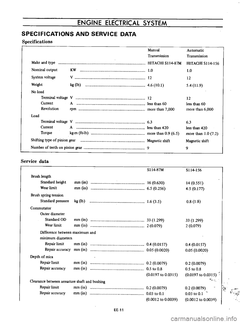
Specified
current
draw
and
revolution
in
these
tests
are
shown
in
specifications
and
service
data
STARTER
MOTOR
s
SWITCH
o
BATTERY
EtJ
VOLTMETER
AMMETER
EE026
Fig
EE
2J
No
load
test
Torque
test
Torque
testing
equipment
should
be
used
to
measure
the
torque
the
motor
will
develop
A
high
current
carrying
variable
resistance
should
be
connected
to
the
circuit
so
that
the
specified
voltage
at
the
starting
motor
may
be
obtained
since
a
small
variation
in
the
voltage
will
produce
a
marked
difference
in
the
torque
development
Specified
power
voltage
and
torque
are
shown
in
Figure
EE
24
EE
9
Page 431 of 513
ENGINE
ElECTRICAL
SYSTEM
SPECIFICATIONS
AND
SERVICE
DATA
Specifications
Manual
Automatic
Transmission
Transmission
Make
and
type
HITACHI
SI14
87M
HITACHI
S114
156
Nominal
output
KW
1
0
1
0
System
voltage
V
12
12
Weight
kg
Qb
4
6
10
1
54
11
9
No
load
Terminal
voltage
V
12
12
Current
A
less
than
60
less
than
60
Revolution
rpm
more
than
7
000
more
than
6
000
Load
Terminal
voltage
V
6
3
6
3
Current
A
less
than
420
less
than
420
Torque
kg
m
ft
Ib
more
than
0
9
6
5
more
than
1
0
7
2
Shifting
type
of
pinion
gear
Magnetic
shift
Magnetic
shift
Number
of
teeth
on
pinion
gear
9
9
Service
data
S114
87M
S114
156
Brush
length
Standard
height
mm
in
16
0
630
14
0
551
Wear
limit
mm
in
6
5
0
256
4
5
0
177
Brush
spring
tension
Standard
pressure
kg
Qb
1
6
3
5
0
8
1
8
Commutator
Outer
diameter
Standard
OD
mm
in
33
1
299
33
I
299
Wear
limit
mm
in
2
0
079
2
0
079
Difference
between
maximum
and
minimum
diameters
Repair
limit
mm
in
0
4
0
0157
0
4
0
0157
Repair
accuracy
mm
in
0
05
0
0020
0
05
0
0020
Depth
of
mica
Repair
limit
mm
in
0
2
0
0079
0
2
0
0079
Repair
accuracy
mm
in
0
5
to
0
8
0
5
to
0
8
0
0197
to
0
0315
0
0197
to
0
0315
Clearance
between
arma
ture
shaft
and
bushing
mm
in
Repair
limit
0
2
0
0079
0
2
0
0079
Vi
Repair
accuracy
mm
in
0
03
to
0
1
0
03
to
0
1
1
r
0
0012
to
0
0039
0
0012
to
0
003Q
EE
11
Page 436 of 513
ENGINE
r
Ignition
switJ
c
o
iArm
ture
j
i
i
VC2
P
tP2
d
I
I
I
PI
I
ll
Rl
L
I
I
lRJ
t
R
I
Field
e
I
I
I
I
Ps
I
1
I
I
n
I
coil
M
4
i
f
I
L
1
J
Alternator
Voltage
regulator
Fig
EE
2B
ChaTging
ciTcuit
II
ALTERNATOR
CONTENTS
DESCRIPTION
REMOVAL
DISASSEMBL
Y
INSPECTION
AND
REPAIR
Rotor
inspection
Inspection
of
stator
I
nspection
of
diode
EE
16
EE
17
EE
17
EE
19
EE
19
EE
19
EE
20
DESCRIPTION
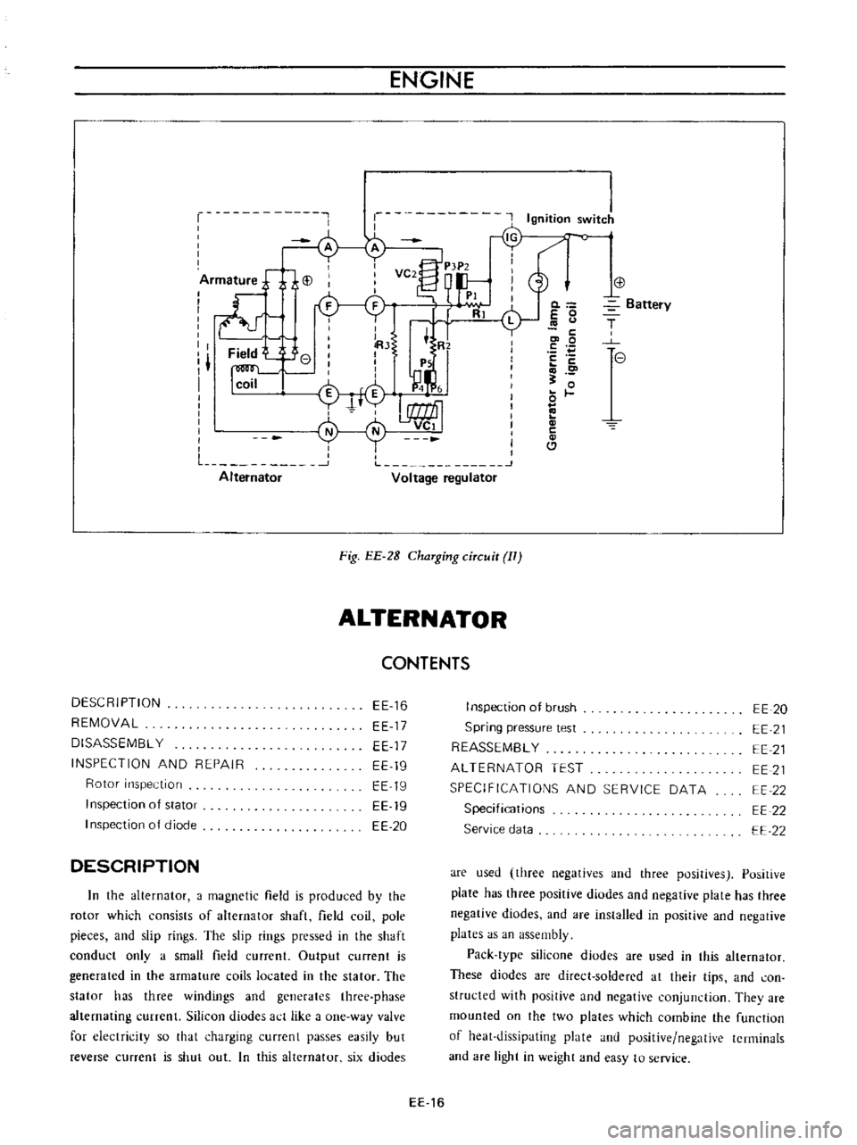
In
the
alternator
a
magnetic
field
is
produced
by
the
rotor
which
consists
of
alternator
shaft
field
coil
pole
pieces
and
slip
rings
The
slip
rings
pressed
in
the
shaft
conduct
only
a
small
field
current
Output
current
is
generated
in
the
armature
coils
located
in
the
stator
The
stator
has
three
windings
and
generates
three
phase
alternating
currenl
Silicon
diudes
act
like
a
one
way
valve
for
electricity
so
that
charging
currcnt
passes
easily
but
reverse
current
is
shut
out
In
this
alternator
six
diodes
0
E
0
c
co
0
E
c
o
0
c
Cl
Battery
T
e
I
nspection
of
brush
Spring
pressure
test
REASSEMBL
Y
ALTERNATOR
TEST
SPECIFICATIONS
AND
SERVICE
DATA
Specifications
Service
data
EE
20
EE
21
EE
21
EE
21
EE
22
EE
22
EE
22
are
used
three
negatives
and
three
positives
Positive
plate
has
three
positive
diodes
and
negative
plate
has
three
negative
diodes
and
are
installed
in
positive
and
negative
plates
as
an
assembly
Pack
type
silicone
diodes
are
used
in
this
alternator
These
diodes
are
direct
soldered
at
their
tips
and
con
structed
with
positive
and
negative
conjunction
They
are
mounted
on
the
two
plates
which
combine
the
function
of
heat
dissipating
plate
and
positive
negative
terminals
and
are
light
in
weight
and
easy
to
service
EE
16
Page 440 of 513
ENGINE
Stator
core
EE044
Fig
EE
41
Testing
stator
for
ground
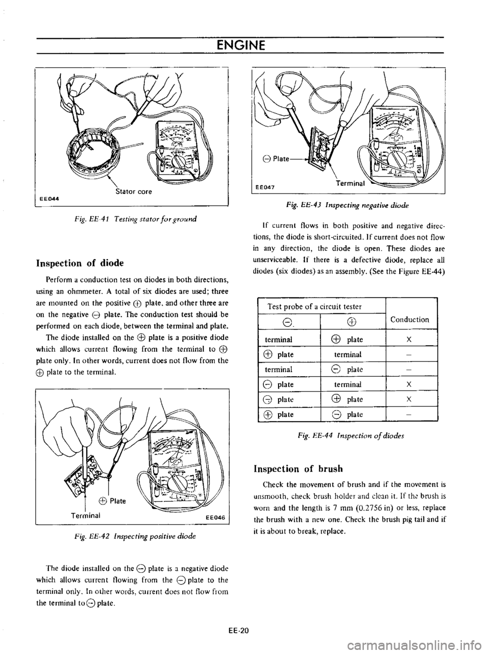
Inspection
of
diode
Perform
a
conduction
test
on
diodes
in
both
directions
using
an
ohmmeter
A
total
of
six
diodes
are
used
three
are
mounted
on
the
positive
EB
plate
and
other
three
are
on
the
negative
3
plate
The
conduction
test
should
be
performed
on
each
diode
between
the
terminal
and
plate
The
diode
installed
on
the
G
l
plate
is
a
positive
diode
which
allows
current
flowing
from
the
terminal
to
G
l
plate
only
In
other
words
current
does
not
flow
from
the
G
l
plate
to
the
terminal
EE046
Fig
EE
42
Inspecting
positive
diode
The
diode
installed
on
the
8
plate
is
a
negative
diode
which
allows
current
flowing
from
the
8
plate
to
the
terminal
only
In
other
words
current
does
not
flow
from
the
terminal
t08
plate
EE
20
8
Plate
EE047
Fig
EE
43
Inspecting
negative
diode
If
current
flows
in
both
positive
and
negative
diree
tions
the
diode
is
short
circuited
If
current
does
not
flow
in
any
direction
the
diode
is
open
These
diodes
are
unserviceable
If
there
is
a
defective
diode
replace
all
diodes
six
diodes
as
an
assembly
See
the
Figure
EE44
I
Test
probe
of
a
circuit
tester
I
8
E8
I
terminal
E8
plate
I
@
plate
terminal
I
terminal
8
plate
18
plate
te
rminal
18
plate
@
plate
18
plate
8
plate
Conduction
x
x
x
Fig
EE
44
lnspection
of
diodes
Inspection
of
brush
Check
the
movement
of
brush
and
if
the
movement
is
unsmooth
check
brush
holder
and
deJn
it
If
th
bmsh
is
worn
and
the
length
is
7
mm
0
2756
in
or
less
replace
the
brush
with
a
new
one
Check
the
brush
pig
tail
and
if
it
is
about
to
break
replace
Page 442 of 513
ENGINE
terminal
to
IN
terminal
or
BAT
terminal
Connect
the
other
test
probe
to
ground
Make
sure
that
voltmeter
registers
battery
voltage
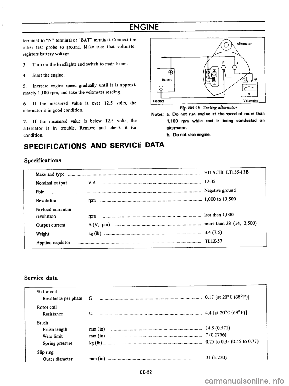
4
Start
the
engine
3
Turn
on
the
headlights
and
switch
to
main
beam
I
o
B
ttefY
E
A
J
0
il
I
5
Increase
engine
speed
gradually
until
it
is
approxi
mately
1
100
rpm
and
take
the
voltmeter
reading
6
If
the
measured
value
is
over
12
5
volts
the
alternator
is
in
good
condition
o
I
eE052
Voltmeter
Fig
EE
49
Testing
altematoT
Notes
8
Do
not
run
engine
at
the
speed
of
more
than
1
100
rpm
while
test
is
being
conducted
on
alternator
b
Do
not
race
engine
7
If
the
measured
value
is
below
12
5
volts
the
alternator
is
in
trouble
Remove
and
check
it
for
condition
SPECIFICATIONS
AND
SERVICE
DATA
Specifications
Make
and
type
Nominal
output
Pole
Revolution
No
load
minimum
revolution
Output
current
Wei
t
Applied
regulator
Service
data
Stator
coil
Resistance
per
phase
Rotor
coil
Resistance
Brush
Brush
length
Wear
limit
Spring
pressure
Slip
ring
Outer
diameter
V
A
HITACHI
LTl35
13B
12
35
rpm
Negative
ground
1
000
to
13
500
rpm
A
V
rpm
kg
1b
less
than
1
000
more
than
28
14
2
500
3
4
7
5
TLl
Z
57
n
0
17
at
200C
680F
n
4
4
at
200e
680
F
mm
in
mm
in
kg
lb
14
5
0
571
7
0
2756
0
25
to
0
35
0
55
to
0
77
mm
in
31
1
220
EE
22
Page 443 of 513
Charge
relay
SPECIFICATIONS
AND
SERVICE
DATA
TROUBLE
DIAGNOSES
AND
CORRECTIONS
ENGINE
ElECTRICAL
SYSTEM
Reduction
limit
Repair
limit
Repair
accuracy
mm
in
mm
in
mm
in
REGULATOR
CONTENTS
DESCRIPTiON
MEASUREMENT
OF
REGULATING
VOLTAGE
ADJUSTMENT
Voltage
regu
lator
EE
23
EE
24
EE
25
EE
25
DESCRIPTION
I
0
0394
0
3
0
0118
0
05
0
0197
EE
26
EE
26
EE
27
1
I
T
r
@
V
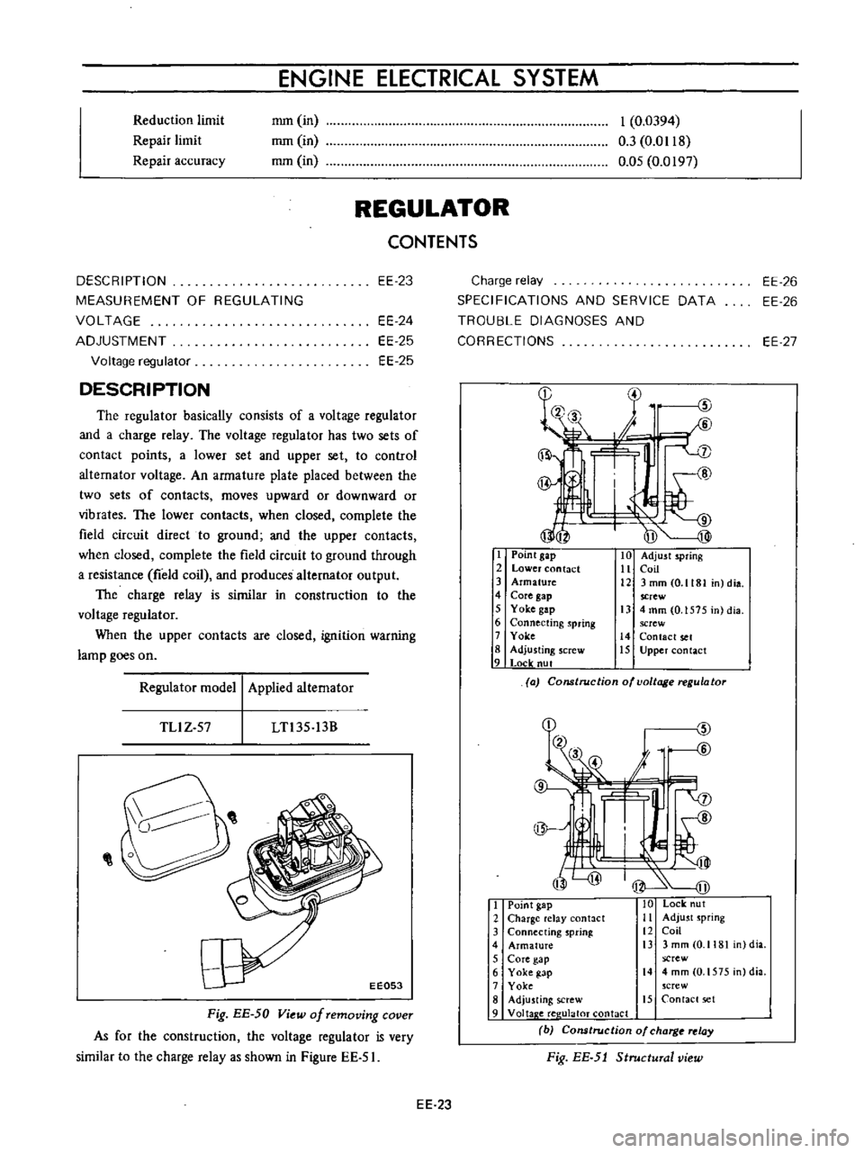
The
regulator
basically
consists
of
a
voltage
regulator
and
a
charge
relay
The
voltage
regulator
has
two
sets
of
contact
points
a
lower
set
and
upper
set
to
control
altemator
voltage
An
armature
plate
placed
between
the
two
sets
of
contacts
moves
upward
or
downward
or
vibrates
The
lower
contacts
when
closed
complete
the
field
circuit
direct
to
ground
and
the
upper
contacts
when
closed
complete
the
field
circuit
to
ground
through
a
resistance
field
coil
and
produces
alternator
output
The
charge
relay
is
similar
in
construction
to
the
voltage
regulator
When
the
upper
contacts
are
closed
ignition
warning
lamp
goes
on
I
Point
gap
2
Lower
contact
3
Armature
4
Core
gap
5
Yoke
gap
6
Connecting
spring
7
Yoke
8
Adjusting
screw
9
Locle
nut
10
Adjust
spring
11
Coil
12
3mmCO
1181
n
dia
screw
13
4
mm
0
1575
in
dia
screw
14
Contact
set
15
Upper
contact
Regulator
model
Applied
alternator
a
Construction
of
voltage
regulator
TLlZ
57
LTl35
13B
I
Point
gap
10
Lock
ut
2
Charge
elay
antact
Ii
Adjust
spring
3
Connecting
sprinl
12
Coil
4
Armature
i3
3
mm
0
1181
dia
5
Core
gap
screw
6
Yoke
gap
14
4mm
O
1575
n
dia
7
Yoke
crew
8
Adju
ting
screw
15
Contact
set
9
Voltap
e
ree
ulaloT
contact
b
Cons
rue
ion
of
charg
relay
Fig
EE
5J
Structural
view
Fig
EE
50
View
of
removing
cover
As
for
the
construction
the
voltage
regulator
is
very
similar
to
the
charge
relay
as
shown
in
Figure
EE
51
EE
23
Page 446 of 513
ENGINE
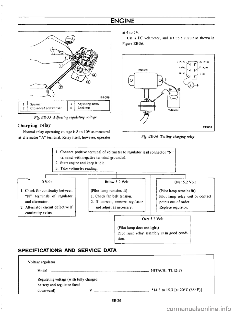
at
4
to
5
V
Use
i
f
DC
voltmeter
and
set
up
a
circuit
as
shown
in
Figure
EE
56
EEQ58
L
W
R
IG
Will
r
AI
W
lli
r
N
Y
vge
I
JJ
Rtl
ublOr
I
I
Spanner
Cross
head
screwdriver
I
I
Adjusting
screw
Lock
nut
Vollm
lcl
Fig
EE
55
Adjusting
Tegulating
voltage
Charging
relay
Normal
relay
operating
voltage
is
8
to
10V
as
measured
at
alternator
A
terminal
Relay
itself
however
operates
EE059
Fig
EE
56
Testing
chaTging
Telay
Connect
positive
terminal
of
voltmeter
to
regulator
lead
connector
N
terminal
with
negative
terminal
grounded
2
Start
engine
and
keep
it
idle
3
Take
voltmeter
reading
o
Volt
Below
5
2
Volt
I
Over
5
2
Volt
I
Check
for
continuity
between
N
terminals
of
regulator
and
alternator
2
Alternator
circuit
defective
if
continuity
exists
pilot
lamp
remains
lit
I
Check
fan
belt
tension
2
If
correct
remove
regulator
and
adjust
as
necessary
Pilot
lamp
remains
lit
Pilot
lamp
relay
coil
or
contact
points
out
of
order
Replace
regulator
Over
5
2
Volt
Pilot
lamp
does
not
light
Pilot
lamp
relay
assembly
is
in
good
condi
tion
SPECIFICATIONS
AND
SERVICE
DATA
Voltage
regulator
Model
HITACHI
TLl
Z
57
Regulating
voltage
with
fully
charged
battery
and
regulator
faced
downward
V
14
3
to
15
3
at
200C
680F
EE
26