Page 449 of 513
ENGINE
ElECTRICAL
SYSTEM
IGNITION
CIRCUIT
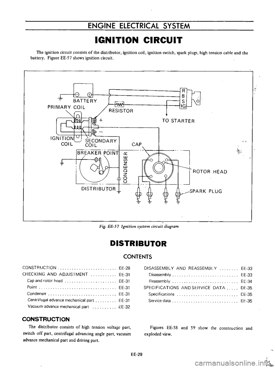
The
ignition
circuit
consists
of
the
distributor
ignition
coil
ignition
switch
spark
plugs
high
tension
cable
and
the
battery
Figure
EE
57
shows
ignition
circuit
8
I
CC
BATTERY
PRIMARY
COIL
SlO
Lf
IGNITION
SECONDARY
COIL
COIL
BREAKER
POINT
jJ
a
w
CI
Z
w
19
DISTRIBUTORI
U
1Fl
r
lB
S
J1G
TO
STARTER
CAP
ROTOR
HEAD
SPARK
PLUG
7
Fig
EE
57
Ignition
system
circuit
diagram
DISTRIBUTOR
CONSTRUCTION
CHECKING
AND
ADJUSTMENT
Cap
and
rotor
head
Point
Condenser
Centrifugal
advance
mechanical
part
Vacuum
advance
mechanical
part
EE
29
EE
31
EE
31
EE
31
EE
31
EE
31
EE
32
CONSTRUCTION
The
distributor
consists
of
high
tension
voltage
part
switch
off
part
centrifugal
advancing
angle
part
vacuum
advance
mechanical
part
and
driving
part
CONTENTS
DISASSEMBLY
AND
REASSEMBLY
Disassembly
Reassembly
SPEC
IFICATIONS
AND
SERVICE
DATA
Specifications
Service
data
EE
33
EE
33
EE
34
EE
35
EE
35
EE
35
Figures
EE
58
and
S9
show
the
construction
and
exploded
view
EE
29
Page 455 of 513
ENGINE
ElECTRICAL
SYSTEM
SPECIFICATIONS
AND
SERVICE
DATA
Specifications
Make
and
type
0412
80
0412
89
for
Manual
for
Automatic
Transmission
Transmission
Firing
order
1
3
4
2
I
3
4
2
Rotating
direction
Counterclockwise
Counterclockwise
Dwell
angle
49
550
49
550
Condenser
capacity
J
lF
0
20
to
0
24
0
20
to
0
24
Service
data
Point
gap
mm
in
0
45
to
0
55
0
0177
to
0
0217
0
50
to
0
65
1
1
to
1
4
Point
pressure
kg
lb
Condenser
capacity
p
F
Micro
Farad
0
20
to
0
24
Condenser
isolate
resistance
M
1
Mega
Ohms
5
Cap
carbon
point
mm
in
rom
in
Housing
inner
diameter
mm
in
12
0
472
0
010
D
0004
12
45
0
020
0
4902
D
0008
12
45
018
0
4902
0007
Shaft
diameter
lower
part
Clearance
between
shaft
and
housing
mm
in
Amendment
limit
of
clearance
mm
in
0
010
to
0
Q38
0
0004
to
0
0015
0
08
0
0031
8
0
005
0
3150
0
0002
D
O
14
D
0006
8
O
15
0
3150
0006
0
005
to
0
029
0
0002
to
0
00
II
Shaft
diameter
upper
part
mm
in
earn
inner
diameter
rom
in
Clearance
between
shaft
and
cam
mm
in
EE
35
Page 457 of 513
ENGINE
ElECTRICAL
SYSTEM
SPECIFICATIONS
Make
and
type
Primary
voltage
v
Spark
gap
mm
in
Primary
resistance
at
200C
680
F
n
Secondary
resistance
at
200C
680F
Kn
External
resistor
at
200C
680
F
n
Applied
resistor
HANSHIN
HITACHI
H5
15
2
C6R
601
12
12
more
than
7
more
than
7
0
28
0
28
1
17
to
I
43
l
l
7
to
I
43
11
2
to
16
8
11
2
to
16
8
l
3tol7
l
3tol7
RC
15
5560R
151O
SPARK
PLUG
CONTENTS
DESCRIPTION
INSPECTION
CLEANING
AND
REGAP
EE
37
EE
37
EE
38
DESCRIPTION
The
spark
plugs
are
of
the
resister
type
having
14
mm
0
551
in
threads
and
0
8
to
0
9
mm
0
031
to
0
Q35
in
gap
Note
All
spark
plugs
installed
on
an
engine
must
be
of
the
same
brand
and
number
of
heat
range
INSPECTION
1
Remove
spark
plug
wire
by
pulling
on
boot
not
on
wire
itself
2
Remove
spark
plugs
3
Check
electrodes
and
inner
and
outer
porcelains
of
plugs
noting
the
type
of
deposits
and
the
degree
of
electrode
erosion
Refer
to
Figure
EE
74
Normal
Brown
to
grayish
tan
deposits
and
slight
elec
trode
wear
indicate
correct
spark
plug
heat
range
SPECIFICATIONS
AND
SERVICE
DATA
TROUBLE
DIAGNOSES
AND
CORRECTIONS
EE
38
EE
39
Carbon
fouled
Dry
fluffy
carbon
deposits
on
the
insula
tor
and
electrode
were
mostly
caused
by
slow
speed
driving
in
city
weak
ignition
too
rich
fuel
mixture
dirty
air
cleaner
etc
H
is
advisable
to
replace
with
plugs
having
hotter
heat
range
Oil
fouled
Wet
black
deposits
show
excessive
oil
en
trance
into
combustion
chamber
through
worn
rings
and
pistons
or
excessive
clearance
between
valve
guides
and
stems
If
the
same
condition
remains
after
repair
use
a
hotter
plug
Overheating
White
or
light
gray
insulator
with
black
or
gray
brown
spots
and
bluish
burnt
electrodes
indicate
engine
overheating
Moreover
the
appearance
results
from
incorrect
ignition
timing
loose
spark
plugs
low
fuel
pump
pressure
wrong
selection
of
fuel
a
hotter
plug
etc
H
is
advisable
to
replace
with
plugs
having
colder
heat
range
EE
37
Page 458 of 513
ENGINE
Overheating
Normal
Carbon
fould
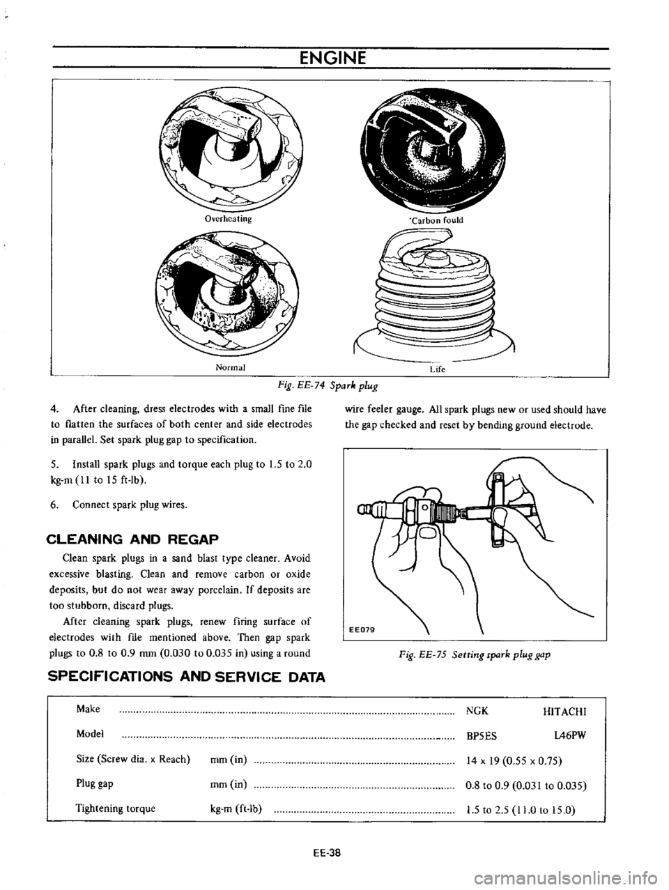
Fig
EE
74
SpaTk
plug
Life
4
After
cleaning
dress
electrodes
with
a
small
fine
fIle
to
flatten
the
surfaces
of
both
center
and
side
electrodes
in
parallel
Set
spark
plug
gap
to
specification
5
Install
spark
plugs
and
torque
each
plug
to
1
5
to
2
0
kg
m
ll
to
15
ft
lb
6
Connect
spark
plug
wires
CLEANING
AND
REGAP
Clean
spark
plugs
in
a
sand
blast
type
cleaner
Avoid
excessive
blasting
Clean
and
remove
carbon
or
oxide
deposits
but
do
not
wear
away
porcelain
If
deposits
are
too
stubborn
discard
plugs
Mter
cleaning
spark
plugs
renew
firing
surface
of
electrodes
with
me
mentioned
above
Then
gap
spark
plugs
to
0
8
to
0
9
mm
0
030
to
0
035
in
using
a
round
SPECIFICATIONS
AND
SERVICE
DATA
Make
Model
Size
Screw
dia
x
Reach
mm
in
Plug
gap
mm
in
Tightening
torque
kg
m
ft
b
EE
38
wire
feeler
gauge
All
spark
plugs
new
or
used
should
have
the
gap
checked
and
reset
by
bending
ground
electrode
Fig
EE
75
Setting
spaTk
plug
gap
NGK
HITACHI
BP5ES
1A6PW
14
x
19
0
55
x
0
75
0
8
to
0
9
0
031
to
0
035
1
5
to
2
5
11
0
to
15
0
Page 461 of 513
DATE
ENGINE
ElECTRICAL
SYSTEM
SERVICE
JOURNAL
OR
BUl
LETIN
REFE
RENCE
JOURNAL
or
BULLETIN
No
PAGE
No
SUBJECT
EE
41
Page 469 of 513
15
Lift
up
the
engine
toward
the
front
INSTALLATION
Install
the
engine
in
reverse
sequence
of
removal
CHASSIS
Fig
ER
14
Lifting
up
engine
SERVICE
JOURNAL
OR
BULLETIN
REFERENCE
DATE
JOURNAL
or
BULLETIN
No
PAGE
No
ER
6
SUBJECT
Page 482 of 513
CHASSIS
SERVICE
DATA
AND
SPECIFICATIONS
Clutch
release
lever
Release
bearing
ta
diaphragm
spring
withdrawal
lever
clearance
Diaphragm
spring
to
flywheel
height
Gutch
disc
Facing
size
Outer
dia
x
inside
dia
x
thickness
Total
friction
area
Thickness
of
disc
assembly
Free
Compressed
Number
of
torsion
spring
Allowable
minimum
depth
of
rivet
head
from
facing
surface
Allowable
facing
run
out
Allowable
free
play
of
spline
Clutch
pedal
Pedal
height
when
not
depressed
Free
travel
of
pedal
head
Pressing
strength
at
full
stroke
Master
cylinder
clutch
Master
cylinder
diameter
Allowable
maximum
clearance
between
cylinder
and
piston
Hydraulic
clutch
0
7
to
I
4
mm
0
0276
to
0
055
in
29
to
31
mm
I
142
to
1
220
in
180
x
125
x
3
5
mm
7
09
x
4
92
x
0
140
in
264
cm2
40
92
sq
in
7
6
to
8
0
mm
0
2992
to
0
3150
in
6
7
to
7
0
mm
0
2638
to
0
2756
in
6
0
3
mm
0
0118
in
0
5
mm
0
0197
in
at
radius
85
mm
3
346
in
0
4
mm
0
0157
in
141
5
mm
5
57
in
30
mm
J
181
in
10
8
kg
23
8
Ib
15
87
mm
5
8
in
0
15
mm
0
0059
in
CL12
Mechanical
clutch
0
9
to
I
2
mm
0
0354
to
0
0472
in
136
5
to
146
5
mm
5
4
to
5
8
in
II
to
15mm
0
433
to
0
591
in
8
3
kg
18
31b
Page 485 of 513
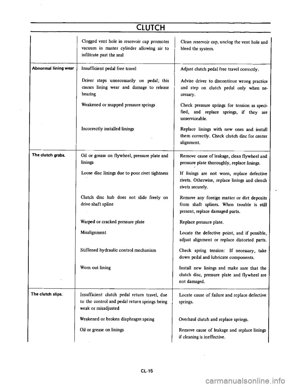
CLUTCH
Clogged
vent
hole
in
reservoir
cap
promotes
vacuum
in
master
cylinder
allowing
air
to
inf1ltrate
past
the
seal
Abnormal
lining
wear
Insufficient
pedal
free
travel
The
clutch
grabs
The
clutch
slips
Driver
steps
unnecessarily
on
pedal
this
causes
lin
jog
wear
and
damage
to
release
bearing
Weakened
or
snapped
pressure
springs
Incorrectly
installed
linings
Oil
or
grease
on
flywheel
pressure
plate
and
linings
Loose
disc
linings
due
to
poor
rivet
tightness
Clutch
disc
hub
does
not
slide
freely
on
drive
shaft
spline
Warped
or
cracked
pressure
plate
Misalignment
Stiffened
hydraulic
control
mechanism
Wom
out
lining
Insufficient
clutch
pedal
return
travel
due
to
the
control
and
pedal
return
springs
being
weak
or
misadjusted
Weakened
or
broken
diaphragm
spring
Oil
or
grease
on
linings
eLl5
Clean
reservoir
cap
unclog
the
vent
hole
and
bleed
the
system
Adjust
clutch
pedal
free
travel
correctly
Advise
driver
to
discontinue
wrong
practice
and
step
on
clutch
pedal
only
when
ne
cessary
Check
pressure
springs
for
tension
as
speci
fied
and
replace
springs
if
they
are
unserviceable
Replace
linings
with
new
ones
and
install
them
correctly
Check
clutch
disc
for
center
alignment
Remove
cause
of
leakage
clean
flywheel
and
pressure
plate
thoroughly
replace
linings
If
linings
are
not
worn
replace
defective
rivets
Otherwise
replace
linings
and
clench
rivets
securely
Remove
any
foreign
matter
or
dirt
deposits
from
shaft
splines
When
trouble
is
still
present
replace
damaged
parts
Replace
pressure
plate
Locate
the
defective
point
and
if
possible
adjust
alignment
or
replace
distorted
parts
Check
spring
tension
If
necessary
take
down
pedal
and
lubricate
components
Install
new
linings
and
make
sure
tha
t
the
clutch
disc
pressure
plate
and
flywheel
are
not
damaged
Locate
cause
of
failure
and
replace
defective
springs
Overhaul
clutch
and
replace
springs
Remove
cause
of
leakage
and
replace
linings
if
cleaning
is
ineffective