Page 290 of 513

III
r
AJ
r
oll
t
1
J
1
J
ti
i
1
tl
FOREWORD
This
scrviee
manual
has
been
prepared
lor
the
purpose
of
assistinf
service
persunnel
of
authorized
NISSAN
DA
TSUN
dealers
in
providing
effective
service
and
maintenance
of
the
1973
Datsun
1200
I
il
Since
proper
maintenance
and
serVIce
are
absolutely
essential
in
satisfying
the
owners
of
DatSlLn
this
manual
should
be
kept
in
a
handy
place
for
ready
reference
and
should
be
mrefully
studied
This
nUl
wal
indudes
procedures
for
maintenance
adjustments
mmor
service
operations
renwval
and
installation
IInd
for
disassembly
and
assembly
of
ram
ponents
The
Quick
Reference
lndex
on
the
first
page
enable
the
user
to
quickly
locate
and
desired
tion
4t
the
beginning
of
each
individual
section
is
a
table
of
contents
which
gives
the
page
number
on
which
each
major
subject
begins
An
index
is
placed
at
the
beginning
of
each
major
subject
withill
the
sectioll
The
Special
Tools
when
required
presented
at
the
Sf
section
411
information
illustrations
and
specificatiolls
contained
in
this
manual
are
based
Oll
the
latest
product
inJormation
available
at
the
time
of
publication
approval
Rights
for
tIltl
rnali
11
of
specificatiuns
llnd
mpthods
at
lilY
time
are
reserved
I
I
I
I
NISSAN
MOTOR
CO
TOKYO
APAN
LTD
f
t
I
I
t
J
1972
NlSSAN
MOTOR
CO
LTD
i
t
r
f
i
o
c
1
I
I
l
1
10
I
It
r
f
K
I
1
I
i
I
r
I
i
i
t
j
I
r
7
T
l
1
r
i
i
t
Llo
tff
t
I
1
O
I
trr
rd
I
At
4
rei
1
0
Ii
0
cll
I
f
I
J
i
J
iF
U
y
tn
1
I
I
I
I
i
t
If
tij
1
li
I
J
H
a
r
1
i
I
V
j
lio
4
l
j
i
y
o
J
A
co
L
i
I
I
I
Jil
iLl4
j
l
t1
J
1
i
t
Page 291 of 513
ti
r
f
o
1
b
4
AI
I
W
n
t
i
i
1
i
f
f
7i
ii
y
0
r
1
J
1
t
I
r
I
DATSUN
1200
SERVICE
MANUAL
MODEL
8110
SERIES
N
I
NISSAN
MOTOR
CO
LTD
TOKYO
JAPAN
j
QUICK
REFERENCE
INDEX
GENERAL
INfORMATION
GI
EMISSION
CONTROL
AND
TUNE
UP
ET
ENGINE
MECHANICAL
EM
REAR
AXlE
8
REAR
SUSPENSiON
BRAKE
WHEEL
AND
TIRE
STEERING
ENGINE
CONTROL
fUEL
8
EXHAUST
BODY
BODY
ElECTRICAL
SERVICE
EQUIPMENT
Page 294 of 513
QUICK
REFERENCE
INDEX
j
DATSUN
1200
SERVICE
MANUAl
MODE
B
110
SERIES
I
Nf
i
l
I
I
N
SSAM
M0101l
CO
tD
TOI
O
JAPAN
Page 295 of 513

r
FOREWORD
This
service
manual
has
been
prepared
for
the
pnrpose
uf
assisling
service
personnel
of
llllthurized
NISSAN
DATSUN
dealers
in
pruviding
e
feetive
service
and
maintenance
uf
the
973
Datsun
2VV
inee
proper
maintenance
and
scroice
arc
absolutely
essential
ill
satisfying
the
uwners
of
Datsun
Ihis
manual
should
be
kepi
in
a
handy
place
fur
ready
reference
and
shollld
be
carefully
studied
This
manual
indudes
procedures
fnr
maintenance
adjlU
tments
mInor
serVice
ofJf
raliun
mmoval
and
inslallation
and
for
disassl
mbly
and
asscmlJl
of
com
ponents
TIle
Ouick
Reji
ence
Index
on
the
jirst
page
enable
the
user
to
quickly
locale
and
de
ired
sed
ion
AI
Ihe
beginning
of
each
individual
see
ion
is
a
lable
of
contents
which
gives
the
page
number
on
which
each
majur
subject
begins
4n
index
is
placed
at
Ihe
beginning
of
each
majur
subject
within
the
section
1
1
Special
Tools
when
required
presented
at
the
SF
sedion
4ll
informatiun
illustrations
arid
specifications
cOlliaifwd
in
this
manual
are
Jw
ed
on
the
latest
product
infurmation
available
at
Ihe
time
of
publication
appruval
Rights
fur
alternatiun
of
specifications
and
methods
at
uny
time
are
reserved
NISSAN
MOTOR
CO
TOKYO
JAPAN
LTD
@
1972
NISSAN
IOTOR
co
LTD
Page 303 of 513

GENERAL
INFORMATION
NISSAN
LONG
LIFE
COOLANT
L
L
C
The
cooling
system
has
been
filled
at
factory
with
the
Long
Life
Coolant
L
L
C
and
water
for
aU
season
protection
This
coolant
provides
freezing
protection
to
150C
50F
in
a
30
Long
Life
Coolant
ratio
and
also
protects
the
engine
against
corrosion
If
outside
tempera
ture
falls
down
to
350C
3IOF
fill
a
50
50
mixture
of
the
Long
Life
Coolant
and
water
The
Long
Life
Coolant
is
an
ethylene
glycol
base
product
containing
any
glyc
erine
ethyl
or
methyl
alcohoL
The
Long
Life
Coolant
must
not
be
mixed
with
any
other
product
scale
nor
sediment
accumulated
in
water
jacket
or
radiator
adverse
ly
affects
heat
radiation
efficiency
When
the
coolant
is
changed
the
system
should
be
thoroughly
flushed
out
by
opening
the
two
drain
plugs
one
at
the
bottom
of
the
radiator
and
the
other
at
the
left
side
of
the
cylinder
block
until
clean
water
comes
out
Always
use
clean
soft
water
in
the
radiator
for
filling
the
radiator
DC
OF
01321
30
1
221
I
I
I
I
1
I
I
I
10
20
30
40
50
10
14
20
1
4
40
1
401
50
581
Fig
GI
13
Protection
concentration
Boiling
point
Percent
0
9
kg
cm2
Freeze
coneen
Sea
level
cooling
sys
protection
tratioo
tern
pressure
30
1060C
1240C
15OC
2210
F
2550
F
5OF
50
1090C
1270C
350C
2280
F
26IOF
3IOF
SERVICE
JOURNAL
OR
BULLETIN
REFERENCE
DATE
JOURNAL
or
BULLETIN
No
PAGE
No
SUBJECT
GI
7
Page 304 of 513
GENERAL
INFORMATION
SERVICE
JOURNAL
OR
BULLETIN
REFERENCE
JOURNAL
or
DATE
BULLETIN
No
PAGE
No
SUBJECT
I
I
I
I
I
I
I
I
I
GI
B
Page 305 of 513
SERV
I
CE
0
M
ANUttlJ
j
f
l
DATSUN
1200
MODEL
B
110
SERIES
rNlSSAN
I
NISSAN
MOTOR
CO
LTD
TOKYO
JAPAN
J
f
p
l
SECTION
ET
GII
EMISSION
CONTROL
AND
TUNE
UP
EMISSION
CONTROL
SYSTEM
AND
ENGINE
TUNE
UP
SERVICE
DATA
AND
SPECIFICATIONS
TROUBLE
DIAGNOSES
AND
CORRECTIONS
Ell
El
25
El
26
Page 327 of 513

ENGINE
6
Start
the
engine
and
continue
idling
as
described
under
paragraphs
I
2
and
3
above
When
several
minutes
have
passed
and
the
valve
is
partially
opened
read
the
thermister
indication
It
is
correct
if
the
reading
falls
between
380C
1000
F
and
550C
1300
F
If
the
reading
is
abnormal
replace
the
sensor
7
On
the
engine
equipped
with
an
idle
compensator
as
service
option
do
as
follows
before
replacing
the
sensor
Clog
hose
on
idle
compensator
side
by
twisting
or
clamping
it
and
check
the
temperature
as
given
in
paragraphs
5
and
6
above
If
the
thermometer
shO
vs
correct
temperature
replace
the
idle
compensa
tOf
if
the
reading
is
abnormal
replace
the
sensor
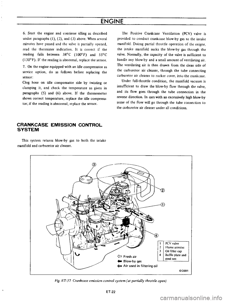
CRANKCASE
EMISSION
CONTROL
SYSTEM
This
system
returns
blow
by
gas
to
both
the
intake
manifold
and
carburetor
air
cleaner
The
Posirive
Crankcase
Ventilation
PCV
valve
is
provided
to
conduct
crankcase
blow
by
gas
to
the
intake
manifold
Duirng
partial
throttle
operation
of
the
enigne
the
intake
manifold
sucks
the
blow
by
gas
through
the
valve
Normally
the
capacity
of
the
valve
is
sufficient
to
handle
any
blow
by
and
a
small
amount
of
ventilating
air
The
ventilating
air
is
then
drawn
from
the
clean
side
of
the
carburetor
air
cleaner
through
the
tube
connecting
carburetor
air
cleaner
to
rocker
cover
intu
the
crankcase
Under
full
throttle
condition
the
manifold
vacuum
is
insufficient
to
draw
the
blow
by
flow
through
the
valve
and
its
flow
goes
through
the
tube
connection
in
the
reverse
direction
In
cars
with
an
excessively
high
blow
by
some
of
the
flow
will
go
through
the
tube
connection
to
the
carburetor
air
cleaner
under
all
conditions
j
Fresh
air
Blow
by
gas
1m
Air
used
in
filtering
oil
t
2
3
4
PCV
valve
Flame
arrester
Oil
filler
cap
Baffle
plate
and
steel
net
ECOOl
Fig
ET
3
7
Crankcase
emission
control
system
at
partially
throttle
open
ET
22