1973 DATSUN B110 ignition
[x] Cancel search: ignitionPage 254 of 513
BODY
ELECTRICAL
SPEEDOMETER
The
speedometer
is
equipped
with
a
total
odometer
which
records
travelled
distance
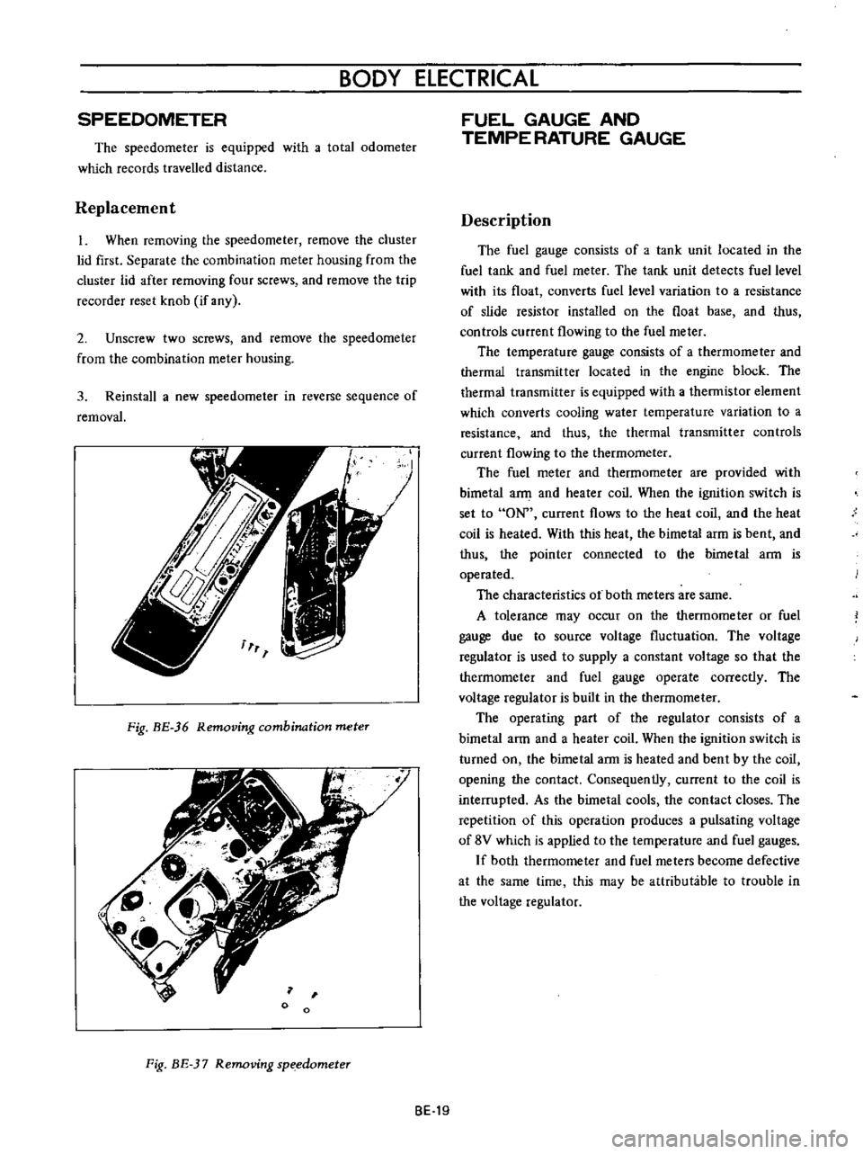
Replacement
1
When
removing
the
speedometer
remove
the
cluster
lid
first
Separate
the
combination
meter
housing
from
the
cluster
lid
after
removing
four
screws
and
remove
the
trip
recorder
reset
knob
if
any
2
Unscrew
two
screws
and
remove
the
speedometer
from
the
combination
meter
housing
3
Reinstall
a
new
speedometer
in
reverse
sequence
of
removal
Fig
BE
36
Removing
combination
meter
o
Fig
BE
37
Removing
sp
edometer
FUEL
GAUGE
AND
TEMPE
RATURE
GAUGE
Description
The
fuel
gauge
consists
of
a
tank
unit
located
in
the
fuel
tank
and
fuel
meter
The
tank
unit
detects
fuel
level
with
its
float
converts
fuel
level
variation
to
a
resistance
of
slide
resistor
installed
on
the
float
base
and
thus
controls
current
flowing
to
the
fuel
meter
The
temperature
gauge
consists
of
a
thermorneter
and
thermal
transmitter
located
in
the
engine
block
The
thermal
transmitter
is
equipped
with
a
thermistor
element
which
converts
cooling
water
temperature
variation
to
a
resistance
and
thus
the
thermal
transmitter
controls
current
flowing
to
the
thermometer
The
fuel
rneter
and
thermometer
are
provided
with
bimetal
a
and
heater
coil
When
the
ignition
switch
is
set
to
ON
current
flows
to
the
heat
coil
and
the
heat
coil
is
heated
With
this
heat
the
bimetal
arm
is
bent
and
thus
the
pointer
connected
to
the
bimetal
ann
is
operated
The
characteristics
ot
both
meters
are
same
A
tolerance
may
occur
on
the
thermometer
or
fuel
gauge
due
to
source
voltage
fluctuation
The
voltage
regulator
is
used
to
supply
a
constant
voltage
so
that
the
therrnorneter
and
fuel
gauge
operate
correctly
The
voltage
regulator
is
built
in
the
thermometer
The
operating
part
of
the
regulator
consists
of
a
bimetal
arm
and
a
heater
coil
When
the
ignition
switch
is
turned
on
the
birnetal
arm
is
heated
and
bent
by
the
coil
opening
the
contact
Consequently
current
to
the
coil
is
interrupted
As
the
bimetal
cools
the
contact
closes
The
repetition
of
this
operation
produces
a
pulsating
voltage
of
8V
which
is
applied
to
the
ternperature
and
fuel
gauges
If
both
thermometer
and
fuel
meters
become
defective
at
the
same
time
this
may
be
attributable
to
trouble
in
the
voltage
regulator
BE
19
Page 255 of 513
BODY
REGULATOR
FUSE
M
TEMPE
RATURE
GAUGE
IGNITION
SWITCH
Lf
I
iT
Ji
1M
THERMAL
TRANSMITTER
I
J
0
I
GAUGE
TANK
UNIT
FUEL
TANK
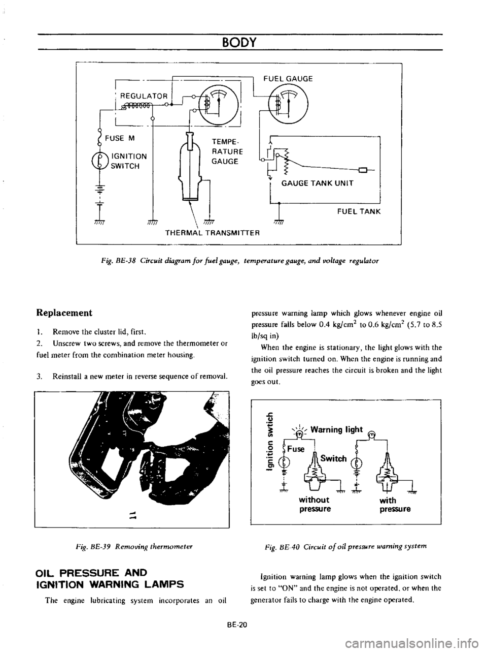
Fig
BE
38
Circuit
diagram
for
fuel
gauge
temperature
gauge
and
voltage
regulator
Replacement
Remove
the
cluster
lid
first
2
Unscrew
two
screws
and
remove
the
thermometer
or
fuel
meter
from
the
combination
meter
housing
3
Reinstall
a
new
meter
in
reverse
sequence
of
removal
Fig
BE
39
Removing
thermometer
OIL
PRESSURE
AND
IGNITION
WARNING
LAMPS
The
engine
lubricating
system
incorporates
an
oil
pressure
warning
lamp
which
glows
whenever
engine
oil
pressure
falls
below
0
4
kg
ern
to
0
6
kg
em
5
7
to
8
5
lb
sq
in
When
the
engine
is
stationary
the
light
glows
with
the
ignition
switch
turned
on
When
the
engine
is
running
and
the
oil
pressure
reaches
the
circuit
is
broken
and
the
light
goes
out
J
u
fj
Warning
lig
2
Fuse
bSM
Q
f
t
J
without
pressu
re
with
pressure
Fig
BE
40
Circuit
of
oil
pressure
warning
system
Ignition
warning
lamp
glows
when
the
ignition
switch
is
set
to
ON
and
the
engine
is
not
operated
or
when
the
generator
fails
to
charge
with
the
engine
operated
BE
20
Page 256 of 513

BODY
ElECTRICAL
When
the
ignition
switch
is
set
to
ON
the
ignition
wa
rning
circuit
is
closed
and
current
flows
flows
from
the
ignition
switch
to
the
warning
lamp
bulb
and
ground
through
the
regulator
When
the
engine
is
started
and
the
generator
comes
into
operation
the
generator
output
current
opposes
the
current
flowing
from
the
warning
lamp
in
effect
it
breaks
the
warning
circuit
ground
connection
and
the
lamp
goes
out
l
r
hffi
u
z
Ignition
switch
I
Q
6
I
0
c
M
1
E
8
ca
i
L
g
PI
lot
c
P
I
j
co
rt
0
relay
E
0
5
y
y
1
N
N
3
Alternator
Regulator
Fig
BE
41
Circuit
of
ignition
warning
system
HAND
BRAKE
WARNING
LAMP
This
lamp
functions
both
hand
brake
warning
larnp
and
BULB
SPECIFICATIONS
service
brake
line
pressure
differential
warning
lamp
When
a
difference
between
front
and
rear
brake
line
pressures
reaches
the
rated
range
13
to
17
kgfcm2
185
to
242
lb
sq
in
the
ground
circuit
for
the
warning
lamp
is
closed
and
the
warning
lamp
lights
IGNITION
SWITCH
WARNING
LAMP
L
E
WARNING
SWITCH
1
SERVICE
BRAKE
LINE
PRESSU
R
E
DIFFERENTIAL
WARNING
J
SWITCH
Fig
BE
42
Circuit
diagram
for
brake
warning
system
tern
Specifications
Square
type
meter
Round
type
meter
Meter
illumination
larnp
VoW
12
3
4
2
12
1
7
3
Turn
signal
pilot
lamp
VoW
12
3
4
2
12
1
7
2
Head
lamp
main
high
beam
VoW
12
3
4
I
12
17
1
pilot
lamp
Ignition
warning
lamp
VoW
123
4
I
12
17
1
Oil
pressure
warning
lamp
VoW
12
3
4
1
12
1
7
1
Hand
brake
warning
lamp
VoW
12
1
7
1
for
U
S
A
CANADA
Clock
illumination
lamp
VoW
123
4
I
12
17
2
Figure
encircled
in
parentheses
indicates
number
of
bulbs
used
BE
21
Page 258 of 513
BODY
ELECTRICAL
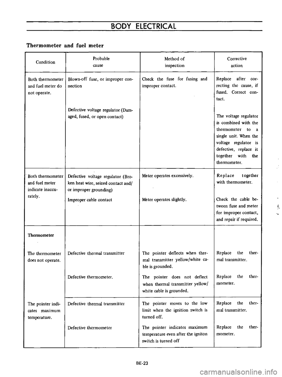
Thermometer
and
fuel
meter
Condition
Both
therrnorneter
and
fuel
rneter
do
not
operate
Both
thermorneter
and
fuel
rneter
indicate
inaccu
rately
Thennometer
Probable
cause
Blown
off
fuse
or
improper
coo
nection
Defective
voltage
regulator
Dam
aged
fused
or
open
contact
Defective
voltage
regulator
Bro
ken
heat
wire
seized
contact
and
or
improper
grounding
Improper
cable
contact
The
thermometer
Defective
thermal
transmitter
does
not
operate
Defective
thermometer
The
pointer
indi
Defective
thermal
transmitter
cates
maximum
temperature
Defective
thermometer
Method
of
inspection
Check
the
fuse
for
fusing
and
improper
contact
Meter
operates
excessively
Meter
operates
slightly
The
pointer
deflects
when
ther
mal
transrnitter
yellow
white
ca
ble
is
grounded
The
pointer
does
not
deflect
when
thermal
transmitter
yellow
white
cable
is
grounded
The
pointer
moves
to
the
low
limit
when
the
ignition
switch
is
turned
off
The
pointer
indicates
maximum
temperature
even
after
the
ignitoD
switch
is
turned
off
BE
23
Corrective
action
Replace
after
cor
recting
the
cause
if
fused
Correct
coo
tact
The
voltage
regulator
is
combined
with
the
thermometer
to
a
single
unit
When
the
voltage
regulator
is
defective
replace
it
together
with
the
thermometer
Replace
together
with
thermometer
Check
the
cable
be
tween
fuse
and
meter
for
improper
contact
and
repair
if
required
Replace
the
ther
mal
transmitter
Replace
the
ther
mometer
Replace
the
ther
mal
transmitter
Replace
the
ther
mometer
Page 259 of 513
The
thermome
ter
does
not
operate
accu
rately
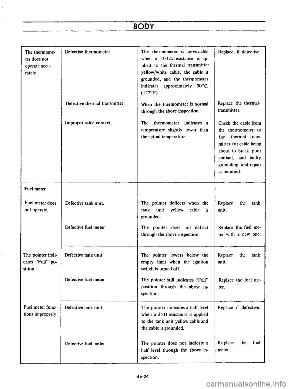
Fuel
meter
Fuel
meter
does
not
operate
Defective
thermometer
Defective
thermal
transmitter
Improper
cable
contact
Defective
tank
unit
Defective
fuel
meter
The
pointer
indi
Defective
tank
unit
cates
Full
po
sition
Fuel
meter
fune
tions
improperly
Defective
fuel
rneter
Defective
tank
unit
Defective
fuel
rneter
BODY
The
thermometer
is
serviceable
when
a
100
n
resistance
is
ap
plied
to
the
thermal
transmitter
yellow
white
cable
the
cable
is
grounded
and
the
thermorneter
indicates
approximately
500C
1220F
When
the
thermometer
is
normal
through
the
above
inspection
The
thermometer
indicates
a
temperature
slightly
lower
than
the
actual
temperature
The
poin
ter
tank
unit
grounded
deflects
yellow
when
the
cable
is
The
pointer
does
not
deflect
through
the
above
inspection
The
pointer
lowers
below
the
ernpty
limit
when
the
ignition
switch
is
turned
off
The
pointer
still
indicates
Full
position
through
the
above
in
spection
The
pointer
indicates
a
half
level
when
a
35
n
resistance
is
applied
to
the
tank
unit
yellow
cable
and
the
cable
is
grounded
The
pointer
does
not
indicate
a
half
level
through
the
above
in
spection
BE
24
Replace
if
defective
Replace
the
therrnal
transmitter
Check
the
cable
from
the
thermometer
to
the
thermal
trans
mitter
for
cable
being
about
to
break
poor
contact
and
faulty
grounding
and
repair
as
required
Replace
unit
the
tank
Replace
the
fuel
me
tee
with
a
new
one
Replace
the
tank
unit
Replace
the
fuel
me
ter
Replace
if
defective
Replace
the
fuel
meter
Page 260 of 513

BODY
ELECTRICAL
Improper
cable
contact
Oil
pressure
and
ignition
warning
lamps
Condition
Oil
pressure
Want
ing
lamp
The
lamp
does
not
ligh
t
when
the
ignition
switch
is
set
to
ON
Probable
cause
Blown
off
fuse
or
faulty
contact
Broken
lamp
bulb
fIlarnent
or
faulty
cable
contact
Defective
oil
pressure
switch
The
lamp
does
not
Oil
pressure
is
too
low
go
out
while
the
engine
is
being
operated
Lack
of
engine
oil
Defective
oil
pressure
switch
Ignition
warning
lamp
The
lamp
does
not
light
when
the
ignition
switch
is
set
to
ON
Blown
off
fuse
or
faulty
contact
Burnt
out
light
bulb
filarnent
or
faulty
cable
contact
The
fuel
rneter
indicates
a
level
slightly
lower
than
the
actual
level
Method
of
inspection
Check
the
fuse
for
fusing
and
faulty
contact
The
warning
lamp
does
not
light
when
oil
pressure
switch
yellow
black
cable
is
grounded
The
warning
lamp
lights
through
the
above
inspection
Inspect
the
engine
oil
pressure
system
Check
oil
level
Continuity
exists
on
the
oil
pres
sure
switch
when
the
engine
is
being
operated
Check
the
fuse
for
fusing
and
faulty
contact
The
pilot
lamp
does
not
light
when
the
voltage
regulator
con
nector
is
disconnected
the
white
red
cable
is
grounded
and
the
ignition
switch
is
set
to
ON
BE
25
Check
the
cable
from
the
fuel
meter
to
the
tank
unit
for
cable
being
about
to
break
poor
contact
and
faulty
grounding
and
repair
as
required
Corrective
action
Replace
after
corree
ting
the
fuse
the
cause
if
fused
Check
the
light
bulb
for
burnt
out
fIla
ment
and
replace
as
required
Replace
the
oil
pres
sure
switch
Add
oil
Replace
the
oil
pres
sure
switch
Repair
or
replace
as
required
Check
the
bulb
for
burnt
out
fIlament
and
replace
as
re
quired
Page 264 of 513
BODY
ELECTRICAL
Improper
stop
position
of
wiper
arm
Improperly
positioned
blade
and
arm
Correct
position
Damaged
or
worn
auto
stop
point
Replace
motor
Improper
wiping
Worn
rubber
blade
Replace
blade
Inadequate
pressing
force
of
wiper
arm
Replace
wiper
arm
IGNITION
SWITCH
AND
STEERING
LOCK
CONTENTS
IGNITION
SWITCH
Removal
IGNITION
SWITCH
WITH
STEER
ING
LOCK
BE
29
BE
29
BE
29
IGNITION
SWITCH
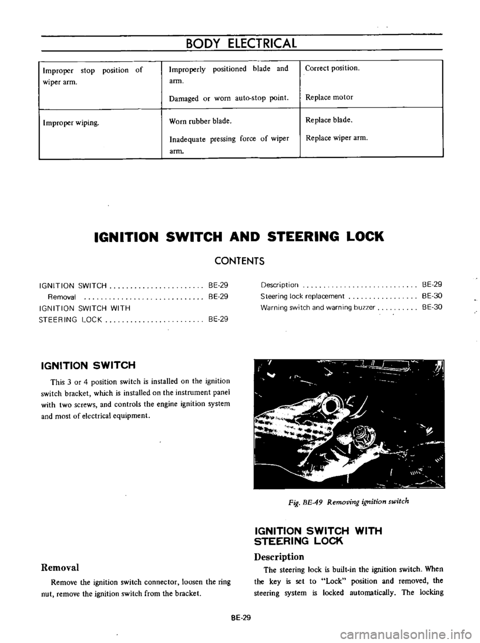
This
3
or
4
position
switch
is
installed
on
the
ignition
switch
bracket
which
is
installed
on
the
instrument
panel
with
two
screws
and
controls
the
engine
ignition
system
and
most
of
electrical
equipment
Removal
Remove
the
ignition
switch
connector
loosen
the
ring
nut
remove
the
ignition
switch
from
the
bracket
Description
Steering
lock
replacement
Warning
switch
and
warning
buzzer
BE
29
BE
30
BE
30
Fig
BE
49
Removing
ignition
switch
IGNITION
SWITCH
WITH
STEERING
LOCK
Description
The
steering
lock
is
built
in
the
ignition
switch
When
the
key
is
set
to
Lock
position
and
rernoved
the
steering
system
is
locked
automatically
The
locking
8E
29
Page 265 of 513

mechanism
is
installed
on
the
steering
jacket
tube
When
the
key
is
set
to
Lock
position
and
removed
the
steering
lock
spindle
is
inserted
in
a
notch
in
the
collar
which
is
stationarity
set
on
the
steering
shaft
to
lock
the
steering
wheel
The
ignitiun
switch
is
installed
on
the
back
of
key
cylinder
with
a
attaching
screw
and
interchangeable
tf
iY
t
7
a
1
Ignition
switch
part
2
Key
cylinder
part
3
Steering
jacket
tube
4
Lock
collar
5
Lock
pindle
6
Steering
shaft
7
Self
shear
type
screw
8
Attaching
screw
Fig
BE
50
Steering
lock
Key
position
Terminal
OFFor
GARAGE
Lock
ON
ST
ART
B
Battery
IG
Ignition
S
Starter
R
Resistance
b
1
Steering
lock
replacement
For
the
purpuse
of
tamper
proof
the
self
shear
type
screws
are
used
and
their
heads
are
sheared
off
when
installed
so
that
the
steering
lock
system
cannot
be
removed
easily
Replace
the
steering
lock
proper
in
accordance
with
the
following
instructions
when
required
Loosen
two
attaching
screws
and
break
the
remaining
twu
self
shear
type
screws
with
a
drill
or
other
proper
tool
Now
remove
the
steering
lock
proper
from
the
BODY
BE
30
steering
jacket
tube
When
installing
a
new
steering
lock
proper
be
sure
tu
tighten
two
new
self
shear
type
screws
to
shear
off
their
heads
Warning
switch
and
warnmg
buzzer
Fig
BE
51
Warning
switch
The
circuit
of
this
warning
system
is
closed
when
the
door
is
opened
with
the
steering
unlocked
because
the
door
switch
and
warning
switch
are
connected
in
series
When
the
cicuit
is
closed
the
buzzer
sounds
When
replacing
the
warning
switch
disconnect
two
cables
remove
the
cap
loosen
two
attaching
screws
and
remove
the
warning
switch
The
warning
buzzer
is
installed
on
the
back
left
side
of
the
instrument
panel
with
two
attaching
screws
FUSE
WARNING
SWITCH
WARN
BUZZ
G
n
WITCH
t
Fig
BE
52
Circuit
diagram
for
warning
system