1973 DATSUN B110 ignition
[x] Cancel search: ignitionPage 423 of 513
ENGINE
ElECTRICAL
SYSTEM
5
If
the
specific
gravity
is
above
1
260
200C
or
680F
after
charging
adjust
it
by
adding
distilled
water
6
Keep
any
open
flame
away
from
the
place
where
the
battery
is
being
charged
7
Replace
vent
plugs
and
clean
the
upper
face
of
the
battery
after
charging
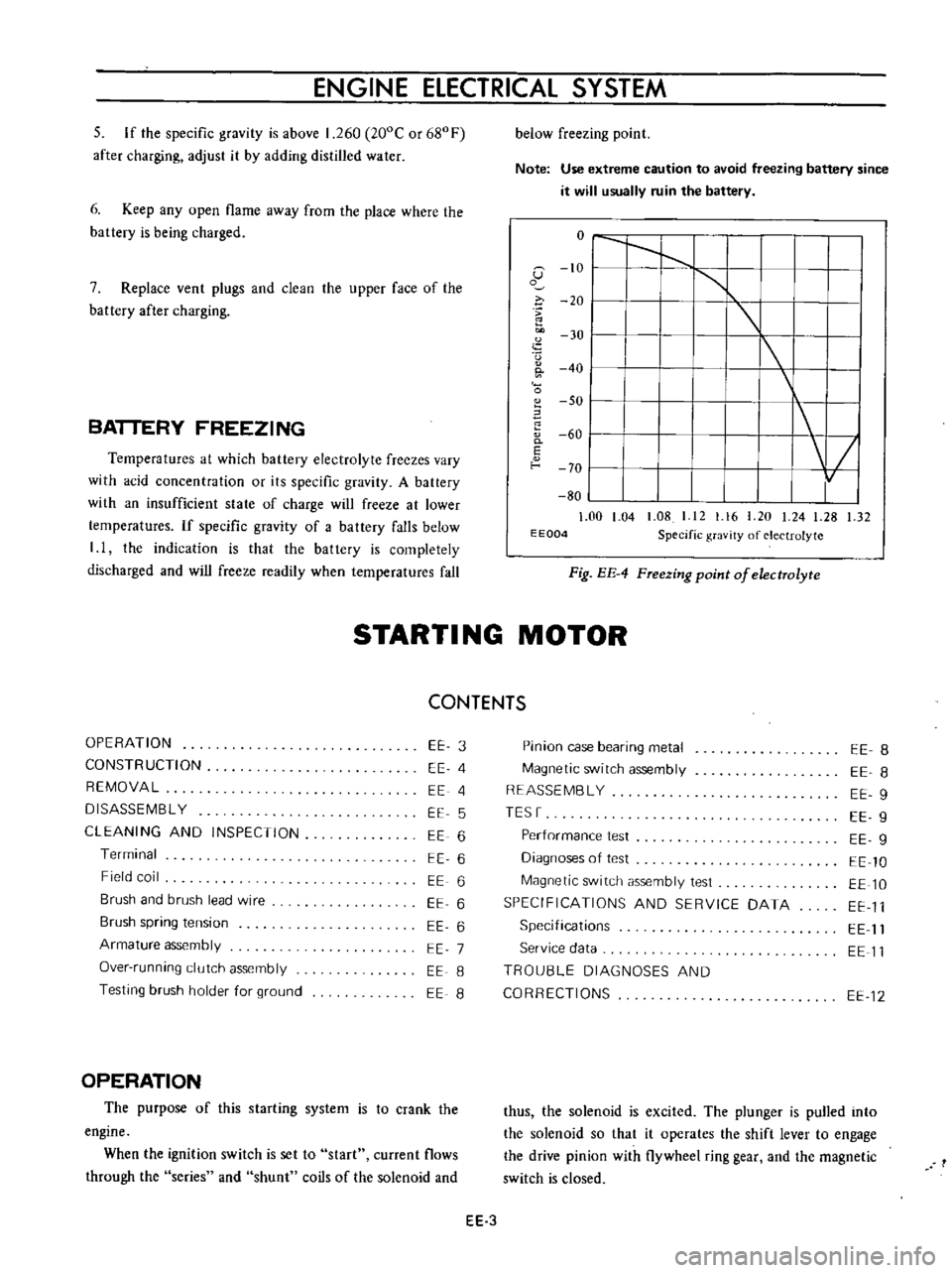
BATTERY
FREEZING
Temperatures
at
which
battery
electrolyte
freezes
vary
with
acid
concentration
or
its
specific
gravity
A
battery
with
an
insufficient
state
of
charge
will
freeze
at
lower
temperatures
If
specific
gravity
of
a
battery
falls
below
I
I
the
indication
is
that
the
battery
is
completely
discharged
and
will
freeze
readily
when
temperatures
fall
below
freezing
point
Note
Use
extreme
caution
to
avoid
freezing
battery
since
it
will
usually
ruin
the
battery
o
I
I
1
G
10
I
1
o
i
20
I
u
30
I
I
0
40
I
0
SO
I
60
0
I
E
f
o
70
I
80
1
00
1
04
1
08
I
12
1
16
20
24
1
28
1
32
E
E004
Specific
gravity
of
electrolyte
Fig
EE
4
FTeezing
point
of
electrolyte
STARTI
NG
MOTOR
CONTENTS
OPERATION
CONSTRUCTION
REMOVAL
DISASSEMBL
Y
CLEANING
AND
INSPECTION
Terminal
Field
coil
Brush
and
brush
lead
wire
Brush
spring
tension
Armature
assembly
Over
running
clutch
assembly
Testing
brush
holder
for
ground
EE
3
EE
4
EE
4
EE
5
EE
6
EE
6
EE
6
EE
6
EE
6
EE
7
EE
8
EE
8
OPERATION
The
purpose
of
this
starting
system
is
to
crank
the
engine
When
the
ignition
switch
is
set
to
start
current
flows
through
the
series
and
shunt
coils
of
the
solenoid
and
Pinion
case
bearing
metal
Magnetic
switch
assembly
REASSEMBL
Y
TESr
Performance
test
Diagnoses
of
test
Magnetic
switch
assembly
test
SPECIFICATIONS
AND
SERVICE
DATA
Specifications
Service
data
TROU8LE
DIAGNOSES
AND
CORRECTIONS
EE
8
EE
8
EE
9
EE
9
EE
g
EE
10
EE
10
EE
11
EE
11
EE
11
EE
12
thus
the
solenoid
is
excited
The
plunger
is
pulled
into
the
solenoid
so
that
it
operates
the
shift
lever
to
engage
the
drive
pinion
with
flywheel
ring
gear
and
the
magnetic
switch
is
closed
EE
3
Page 424 of 513
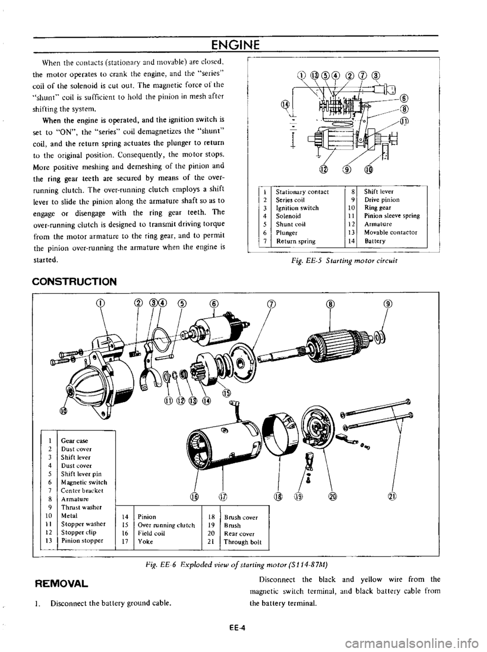
When
the
contacts
stationary
and
movable
are
dused
the
motor
operates
to
crank
the
engine
and
the
series
coil
of
the
solenoid
is
cut
out
The
magnetic
force
of
the
shunt
coil
is
sufficient
to
hold
the
pinion
in
mesh
after
shifting
the
system
When
the
engine
is
operated
and
the
ignition
switch
is
set
to
ON
the
series
coil
demagnetizes
the
shunt
coil
and
the
return
spring
actuates
the
plunger
to
return
to
the
original
position
Consequently
the
motor
stops
More
positive
meshing
and
demeshing
of
the
pinion
and
the
ring
gear
teeth
are
secured
by
means
of
the
over
running
clutch
The
over
running
clutch
employs
a
shift
lever
to
slide
the
pinion
along
the
armature
shaft
so
as
to
engage
or
disengage
with
the
ring
gear
teeth
The
over
running
clutch
is
designed
to
transmit
driving
torque
from
the
motor
armature
to
the
ring
gear
and
to
permit
the
pinion
over
running
the
armature
when
the
engine
is
started
ENGINE
ijJ
1
t
2
3
4
5
6
7
Stationary
contact
Serie
coil
Ignition
switch
Solenoid
Shunt
coil
Plunger
Return
spring
8
Shift
lever
9
Drive
pinion
10
Ring
gear
11
Pinion
sleeve
spring
12
Armature
13
Movable
contactor
14
Battery
Fig
EE
5
Starting
motor
circuit
CONSTRUCTION
1
2
3
4
5
6
7
8
9
10
11
12
13
j
@
Gear
case
Du
t
cover
Shift
lever
Dust
cover
Shift
lever
pin
Magnetic
switch
Center
bracket
Armature
Thrust
washer
Metal
Stopper
washer
Stopper
l
lip
Pinion
stopper
@
@
o
@
i
1I
@
@
@
14
15
t6
17
Pinion
Over
running
clutch
Field
coil
Yoke
18
B
rush
cover
19
Brush
20
Rear
cover
21
Through
bolt
Fig
EE
6
Exploded
view
of
staTting
motoT
SI14
B7M
Disconnect
the
black
and
yellow
wire
from
the
magnetic
switch
terminal
and
black
battery
cable
from
the
battery
terminal
REMOVAL
I
Disconnect
the
ballery
ground
cable
EE
4
Page 430 of 513
ENGINE
Characteristic
curve
i
8
s
l00
0
OJ
m
v
1
2
1
0
tc
0
8
E
u
6
E
o
4
0
2
L
c
0
00
J
300
Current
IAI
Fig
EE
24
Characteristic
curve
of
S
114
B
7M
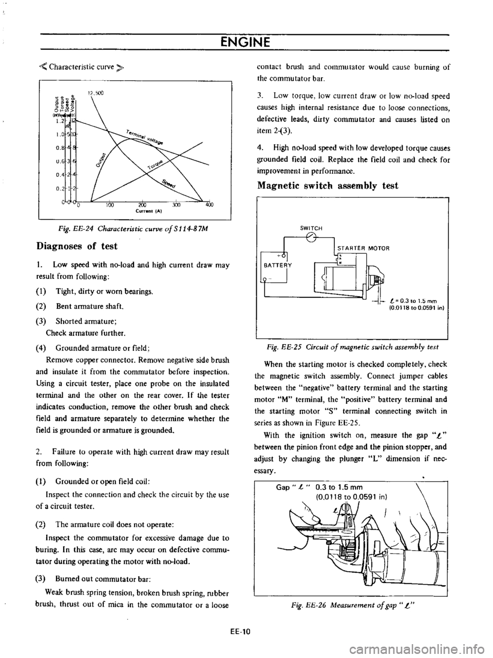
Diagnoses
of
test
1
Low
speed
with
no
load
and
high
current
draw
may
result
from
following
1
Tight
dirty
or
worn
bearings
2
Bent
armature
shaft
3
Shorted
armature
Check
armature
further
4
Grounded
armature
or
field
Remove
copper
connector
Remove
negative
side
brush
and
insulate
it
from
the
commutator
before
inspection
Using
a
circuit
tester
place
one
probe
on
the
insulated
terminal
and
the
other
on
the
rear
cover
If
the
tester
indicates
conduction
remove
the
other
brush
and
check
field
and
armature
separately
to
determine
whether
the
field
is
grounded
or
armature
is
grounded
2
Failure
to
operate
with
high
current
draw
may
result
from
following
I
Grounded
or
open
field
coil
Inspect
the
connection
and
check
the
circuit
by
the
use
of
a
circuit
tester
2
The
armature
coil
does
not
operate
Inspect
the
commutator
for
excessive
damage
due
to
buring
In
this
case
arc
may
occur
on
defective
commu
tator
during
operating
the
motor
with
no
load
3
Burned
out
commutator
bar
Weak
brush
spring
tension
broken
brush
spring
rubber
brush
thrust
out
of
mica
in
the
commutator
or
a
loose
EE
10
contact
brush
and
commutator
would
cause
burning
of
the
commutator
bar
3
Low
torque
low
current
draw
or
low
no
load
speed
causes
high
internal
resistance
due
to
loose
connections
defective
leads
dirty
commutator
and
causes
listed
on
item
2
3
4
High
no
load
speed
with
low
developed
torque
causes
grounded
field
coil
Replace
the
field
coil
and
check
for
improvement
in
performance
Magnetic
switch
assembly
test
SWITCH
STARTER
MOTOR
61
1u
i
T
0
0118
to
0
0591
n
Fig
EE
25
Circuit
of
magnetic
switch
assembly
test
When
the
starting
motor
is
checked
completely
check
the
magnetic
switch
assembly
Connect
jumper
cables
between
the
negative
battery
terminal
and
the
starting
motor
lM
terminal
the
positive
battery
terminal
and
the
starting
motor
S
terminal
connecting
switch
in
series
as
shown
in
Figure
EE
25
With
the
ignition
switch
on
measure
the
gap
I
between
the
pinion
front
edge
and
the
pinion
stopper
and
adjust
by
changing
the
plunger
L
dimension
if
nec
essary
Gap
l
0
3
to
1
5
mm
0
0118
to
0
0591
in
l
Fig
EE
26
Measurement
of
gap
L
Page 432 of 513

ENGINE
Arma
ture
shaft
Outer
diameter
Pinion
side
mm
in
12
950
to
12
968
0
5082
to
0
5105
11
450
to
II
468
0
4507
to
0
4515
0
1
0
0039
0
08
0
0031
Rear
end
mm
in
Wear
limit
Bend
limit
mm
in
mm
in
Gap
1
between
the
pinion
front
edge
and
the
pinion
stopper
mm
in
0
3
to
1
5
0
0118
to
0
0591
Magnetic
switch
Coil
resistance
Series
cuil
Q
Shunt
coil
n
Plunger
L
dimension
mm
in
0
3
at
20De
68UF
0
9
at
ooe
680F
317t032
3
l
248
to
1
272
TROUBLE
DIAGNOSES
AND
CORRECTIONS
12
950
to
12
968
0
5082
to
0
5105
11
450
to
II
468
0
4507
to
0
4515
l
0
1
0
0039
0
08
0
0031
0
3
to
1
5
0
0118
to
0
0591
0
3
at
20De
680Fl
0
9
at
200e
680F
317
to
32
3
l
248
to
I
272
Troubles
Trouble
location
Causes
Remedies
Starting
motor
will
not
operate
No
magnetic
switch
Battery
Defective
battery
Replace
battery
operating
sound
Over
discharging
Measure
specific
gravity
of
e
Ie
ctrolyte
and
ch
lrge
or
replace
the
battery
Ignition
switch
Defective
contact
Correct
or
replace
ig
nition
switch
Wiring
Faulty
starting
motor
grounding
Correct
Faulty
battery
grounding
Correct
Broken
or
disconnected
cable
Correct
or
replace
EE
12
Page 434 of 513

Pinion
intermeshes
with
ring
gear
Starting
motor
rotates
and
pinion
intermeshes
with
ring
gear
but
ro
tation
is
too
slow
When
starting
switch
is
set
to
OFF
the
start
ing
motor
does
not
stop
Starting
motor
Battery
Wiring
Ignition
switch
Starting
motor
Ignition
switch
Magnetic
switch
Starting
motor
ENGINE
Faulty
pinion
sliding
Dropped
off
lever
pin
Excessive
plunger
L
dimension
Defective
over
running
clutch
Over
discharging
Improper
or
loose
terminal
contact
Improperly
tightened
connection
Rough
contact
surface
Shorted
armature
coil
or
field
coil
Worn
brush
or
insufficient
spring
pressure
Contaminated
commutator
or
im
proper
brush
contact
Defective
mica
Lack
of
metal
lubrication
Armature
contacted
with
pole
core
Faulty
returning
Seized
contact
Shorted
coil
Faulty
plunger
sliding
Pinion
does
not
disengage
from
the
ring
gear
smoothly
Pinion
spline
does
not
disengage
smoothly
Seized
pinion
metal
EE
14
Repair
Repair
Adjust
Replace
Charge
battery
Repair
and
retighten
Retighten
Repair
or
replace
Repair
or
replace
Repair
or
replace
Repair
Repair
Repair
or
replace
Repair
or
replace
Replace
Replace
Replace
Replace
Repair
or
replace
Repair
or
replace
Replace
Page 435 of 513
ENGINE
ElECTRICAL
SYSTEM
CHARGING
CIRCUIT
IGNITION
1
i
n
ITCH
r
B
i
i
vel
oU
ARMATURE
lip
J
l
t
lJ
FIEL
Df
e
I
I
3
2
I
u
P
5
0
IL
U
p
P
f
H
i
I
I
L
J
L
J
ALTERNATOR
VOL
TAGE
REGULATOR
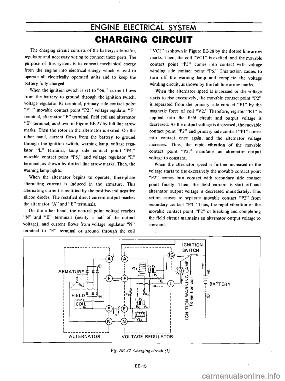
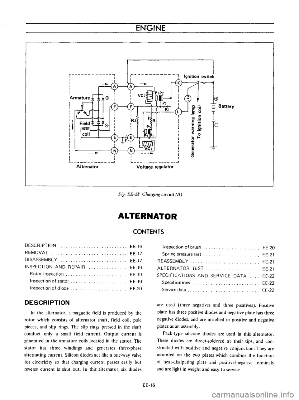
The
charging
circuit
consists
of
the
battery
alternator
regulator
and
necessary
wiring
to
connect
these
parts
The
purpose
of
this
system
is
to
convert
mechanical
energy
from
the
engine
into
electrical
energy
which
is
used
to
operate
all
electrically
operated
units
and
to
keep
the
battery
fully
charged
When
the
ignition
switch
is
set
to
on
current
flows
from
the
battery
to
ground
through
the
ignition
switch
voltage
regulator
IG
terminal
primary
side
contact
point
PI
movable
contact
point
P2
voltage
regulator
F
terminal
alternator
F
terminal
field
coil
and
alternator
E
terminal
as
shown
in
Figure
EE
27
by
full
line
arrow
marks
Then
the
rotor
in
the
alternator
is
exited
On
the
other
hand
current
flows
from
the
battery
to
ground
through
the
ignition
switch
warning
lamp
voltage
regu
lator
L
terminal
lamp
side
contact
point
P4
movable
contact
point
PS
and
voltage
regulator
E
terminal
as
shown
by
dotted
line
arrow
marks
Then
the
warning
lamp
ligh
ts
When
the
alternator
begins
to
operate
three
phase
alternating
current
is
induced
in
the
armature
This
alternating
current
is
rectified
by
the
positive
and
negative
silicon
diodes
The
rectified
direct
current
output
reaches
the
alternator
A
and
E
terminals
On
the
other
hand
the
neutral
point
voltage
reaches
N
and
E
terminals
nearly
a
half
of
the
output
voltage
and
current
flows
from
voltage
regulator
N
terminal
to
E
terminal
or
ground
through
the
coil
VCI
as
shown
in
Figure
EE
28
by
the
dolled
line
arrow
marks
Then
the
coil
vc
I
is
excited
and
the
movable
contact
point
P5
comes
into
contact
with
voltage
winding
side
contact
point
P6
This
action
causes
to
turn
off
the
warning
lamp
and
complete
the
voltage
winding
circuit
as
shown
by
the
ullline
arrow
marks
When
the
alternator
speed
is
increased
or
the
voltage
starts
to
rise
excessively
the
movable
contact
point
P2
is
separated
from
the
primary
side
contact
P
1
by
the
magnetic
force
of
coil
V2
Therefore
register
RI
is
applied
into
the
field
circuit
and
output
voltage
is
decreased
As
the
outpu
t
voltage
is
decreased
the
movable
contact
point
P2
and
primary
side
contact
PI
comes
into
contact
once
again
and
the
alternator
voltage
increases
Thus
the
rapid
vibration
of
the
movable
contact
point
P2
maintains
an
alternator
output
voltage
to
constant
When
the
alternator
speed
is
further
increased
or
the
voltage
starts
to
rise
excessively
the
movable
contact
point
P2
comes
into
contact
with
secondary
side
contact
point
finally
Then
the
field
current
is
shut
off
and
alternator
output
voltage
is
decreased
immediately
This
action
causes
to
separate
movable
contact
P2
from
secondary
contact
P3
Thus
the
rapid
vibration
of
the
movable
contact
point
P2
or
breaking
and
completing
the
field
circuit
maintains
an
alternator
output
voltage
to
constant
j
T
SA
TIERY
I
l
e
7
Fig
EE
27
ChaTging
ciTcuit
1
EE
15
Page 436 of 513
ENGINE
r
Ignition
switJ
c
o
iArm
ture
j
i
i
VC2
P
tP2
d
I
I
I
PI
I
ll
Rl
L
I
I
lRJ
t
R
I
Field
e
I
I
I
I
Ps
I
1
I
I
n
I
coil
M
4
i
f
I
L
1
J
Alternator
Voltage
regulator
Fig
EE
2B
ChaTging
ciTcuit
II
ALTERNATOR
CONTENTS
DESCRIPTION
REMOVAL
DISASSEMBL
Y
INSPECTION
AND
REPAIR
Rotor
inspection
Inspection
of
stator
I
nspection
of
diode
EE
16
EE
17
EE
17
EE
19
EE
19
EE
19
EE
20
DESCRIPTION
In
the
alternator
a
magnetic
field
is
produced
by
the
rotor
which
consists
of
alternator
shaft
field
coil
pole
pieces
and
slip
rings
The
slip
rings
pressed
in
the
shaft
conduct
only
a
small
field
current
Output
current
is
generated
in
the
armature
coils
located
in
the
stator
The
stator
has
three
windings
and
generates
three
phase
alternating
currenl
Silicon
diudes
act
like
a
one
way
valve
for
electricity
so
that
charging
currcnt
passes
easily
but
reverse
current
is
shut
out
In
this
alternator
six
diodes
0
E
0
c
co
0
E
c
o
0
c
Cl
Battery
T
e
I
nspection
of
brush
Spring
pressure
test
REASSEMBL
Y
ALTERNATOR
TEST
SPECIFICATIONS
AND
SERVICE
DATA
Specifications
Service
data
EE
20
EE
21
EE
21
EE
21
EE
22
EE
22
EE
22
are
used
three
negatives
and
three
positives
Positive
plate
has
three
positive
diodes
and
negative
plate
has
three
negative
diodes
and
are
installed
in
positive
and
negative
plates
as
an
assembly
Pack
type
silicone
diodes
are
used
in
this
alternator
These
diodes
are
direct
soldered
at
their
tips
and
con
structed
with
positive
and
negative
conjunction
They
are
mounted
on
the
two
plates
which
combine
the
function
of
heat
dissipating
plate
and
positive
negative
terminals
and
are
light
in
weight
and
easy
to
service
EE
16
Page 443 of 513
Charge
relay
SPECIFICATIONS
AND
SERVICE
DATA
TROUBLE
DIAGNOSES
AND
CORRECTIONS
ENGINE
ElECTRICAL
SYSTEM
Reduction
limit
Repair
limit
Repair
accuracy
mm
in
mm
in
mm
in
REGULATOR
CONTENTS
DESCRIPTiON
MEASUREMENT
OF
REGULATING
VOLTAGE
ADJUSTMENT
Voltage
regu
lator
EE
23
EE
24
EE
25
EE
25
DESCRIPTION
I
0
0394
0
3
0
0118
0
05
0
0197
EE
26
EE
26
EE
27
1
I
T
r
@
V
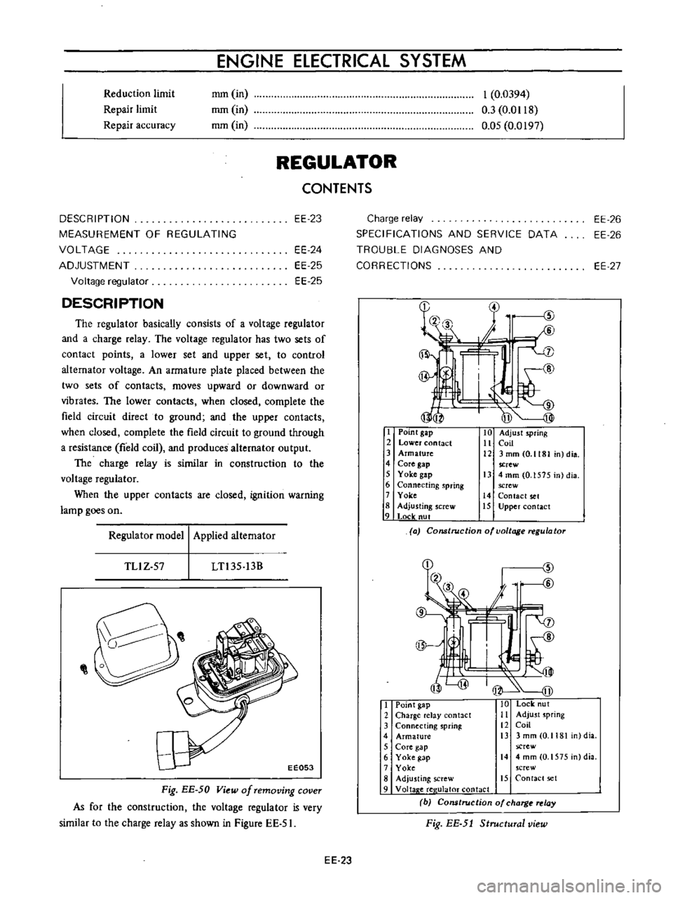
The
regulator
basically
consists
of
a
voltage
regulator
and
a
charge
relay
The
voltage
regulator
has
two
sets
of
contact
points
a
lower
set
and
upper
set
to
control
altemator
voltage
An
armature
plate
placed
between
the
two
sets
of
contacts
moves
upward
or
downward
or
vibrates
The
lower
contacts
when
closed
complete
the
field
circuit
direct
to
ground
and
the
upper
contacts
when
closed
complete
the
field
circuit
to
ground
through
a
resistance
field
coil
and
produces
alternator
output
The
charge
relay
is
similar
in
construction
to
the
voltage
regulator
When
the
upper
contacts
are
closed
ignition
warning
lamp
goes
on
I
Point
gap
2
Lower
contact
3
Armature
4
Core
gap
5
Yoke
gap
6
Connecting
spring
7
Yoke
8
Adjusting
screw
9
Locle
nut
10
Adjust
spring
11
Coil
12
3mmCO
1181
n
dia
screw
13
4
mm
0
1575
in
dia
screw
14
Contact
set
15
Upper
contact
Regulator
model
Applied
alternator
a
Construction
of
voltage
regulator
TLlZ
57
LTl35
13B
I
Point
gap
10
Lock
ut
2
Charge
elay
antact
Ii
Adjust
spring
3
Connecting
sprinl
12
Coil
4
Armature
i3
3
mm
0
1181
dia
5
Core
gap
screw
6
Yoke
gap
14
4mm
O
1575
n
dia
7
Yoke
crew
8
Adju
ting
screw
15
Contact
set
9
Voltap
e
ree
ulaloT
contact
b
Cons
rue
ion
of
charg
relay
Fig
EE
5J
Structural
view
Fig
EE
50
View
of
removing
cover
As
for
the
construction
the
voltage
regulator
is
very
similar
to
the
charge
relay
as
shown
in
Figure
EE
51
EE
23