1973 DATSUN B110 ignition
[x] Cancel search: ignitionPage 337 of 513
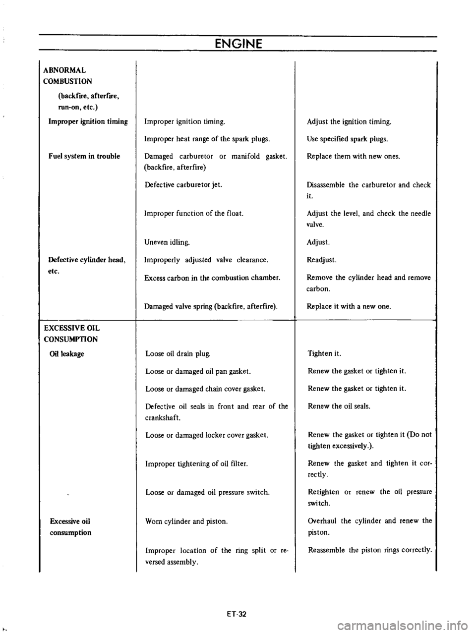
ABNORMAL
COMBUSTION
backfire
afterflfe
run
on
etc
Improper
ignition
timing
Fuel
system
in
trouble
Defective
cylinder
head
etc
EXCESSIVE
OIL
CONSUMPTION
Oil
leakage
Excessive
oil
consumption
ENGINE
Improper
ignition
timing
Improper
heat
range
of
the
spark
plugs
Damaged
carburetor
or
manifold
gasket
backfire
afterflre
Defective
carburetor
jet
Improper
function
of
the
float
Uneven
idling
Improperly
adjusted
valve
clearance
Excess
carbon
in
the
combustion
chamber
Damaged
valve
spring
backfire
afterure
Loose
oil
drain
plug
Loose
or
damaged
oil
pan
gasket
Loose
or
damaged
chain
cover
gasket
Defective
oil
seals
in
front
and
rear
of
the
crankshaft
Loose
or
damaged
locker
cover
gasket
Improper
tightening
of
oil
filter
Loose
or
damaged
oil
pressure
switch
Worn
cylinder
and
piston
Improper
location
of
the
ring
split
or
reo
versed
assembly
ET
32
Adjust
the
ignition
timing
Use
specified
spark
plugs
Replace
them
with
new
ones
Disassemble
the
carburetor
and
check
it
Adjust
the
level
and
check
the
needle
valve
Adjust
Readjust
Remove
the
cylinder
head
and
remove
carbon
Replace
it
with
a
new
one
Tighten
it
Renew
the
gasket
or
tighten
it
Renew
the
gasket
or
tighten
it
Renew
the
oil
seals
Renew
the
gasket
or
tighten
it
Do
not
tighten
excessively
Renew
the
gasket
and
tighten
it
cor
rectly
Retighten
or
renew
the
oil
pressure
switch
Overhaul
the
cylinder
and
renew
the
piston
Reassemble
the
piston
rings
correctly
Page 400 of 513
FUEl
SYSTEM
Secondary
throttle
valve
is
operated
by
throttle
lever
The
high
power
and
good
acceleration
are
gained
with
combination
of
the
auxiliary
valve
2
Accelerating
pump
gives
excellent
acceleration
3
The
power
valve
mechanism
is
of
a
vacuum
actuated
boost
type
and
improves
high
speed
driving
4
The
throttle
opener
control
system
Refer
to
Section
ET
incorporates
a
servo
diaphragm
The
servo
dia
phragm
helps
open
the
throttle
valve
at
a
decreasing
speed
so
as
to
reduce
the
emission
of
hydrocarbons
to
a
minimum
5
An
anti
dieseling
solenoid
is
used
as
a
means
of
preventing
dieseling
When
the
ignition
key
is
turned
off
the
fuel
passage
involved
in
the
slow
system
is
closed
and
the
fuel
supply
is
shut
down
completely
6
In
the
choke
mechanism
an
electric
automatic
choke
is
used
to
automatically
control
the
choke
valve
operation
during
the
warm
up
of
the
engine
7
The
carburetor
for
automatic
transmission
is
equipped
with
so
called
dash
pot
that
is
it
makes
smooth
decelerating
without
engine
stall
at
any
operating
condi
tion
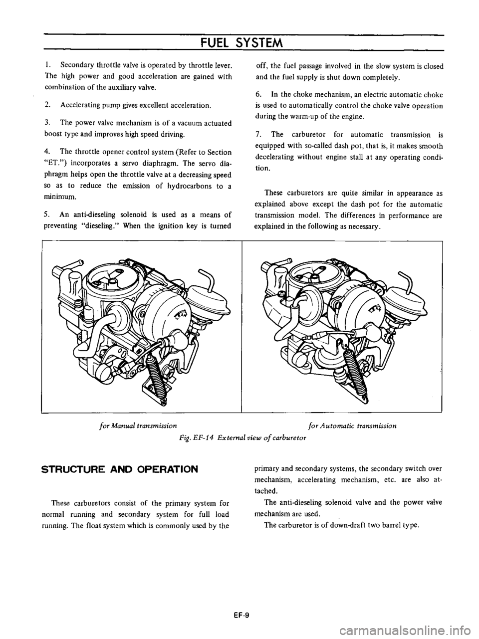
These
carburetors
are
quite
similar
in
appearance
as
explained
above
except
the
dash
pot
for
the
au
tomatic
transmission
model
The
differences
in
performance
are
explained
in
the
following
as
necessary
for
Manual
transmission
for
4utomatic
transmission
Fig
EF
14
External
view
of
carburetor
STRUCTURE
AND
OPERATION
These
carburetors
consist
of
the
primary
system
for
normal
running
and
secondary
system
for
full
load
running
The
float
system
which
is
commonly
used
by
the
primary
and
secondary
systems
the
secondary
switch
over
mechanism
accelerating
mechanism
etc
are
also
at
tached
The
anti
dieseling
solenoid
valve
and
the
power
valve
mechanism
are
used
The
carburetor
is
of
down
draft
two
barrel
type
EF
9
Page 403 of 513
ENGINE
Step
system
The
construction
of
this
system
corresponds
to
the
idling
and
slow
system
of
the
primary
system
This
system
aims
at
the
power
filling
up
of
the
gap
when
fuel
supply
is
transferred
from
the
primary
system
to
the
secondary
system
The
step
port
is
located
near
the
auxiliary
valve
in
its
fully
closed
state
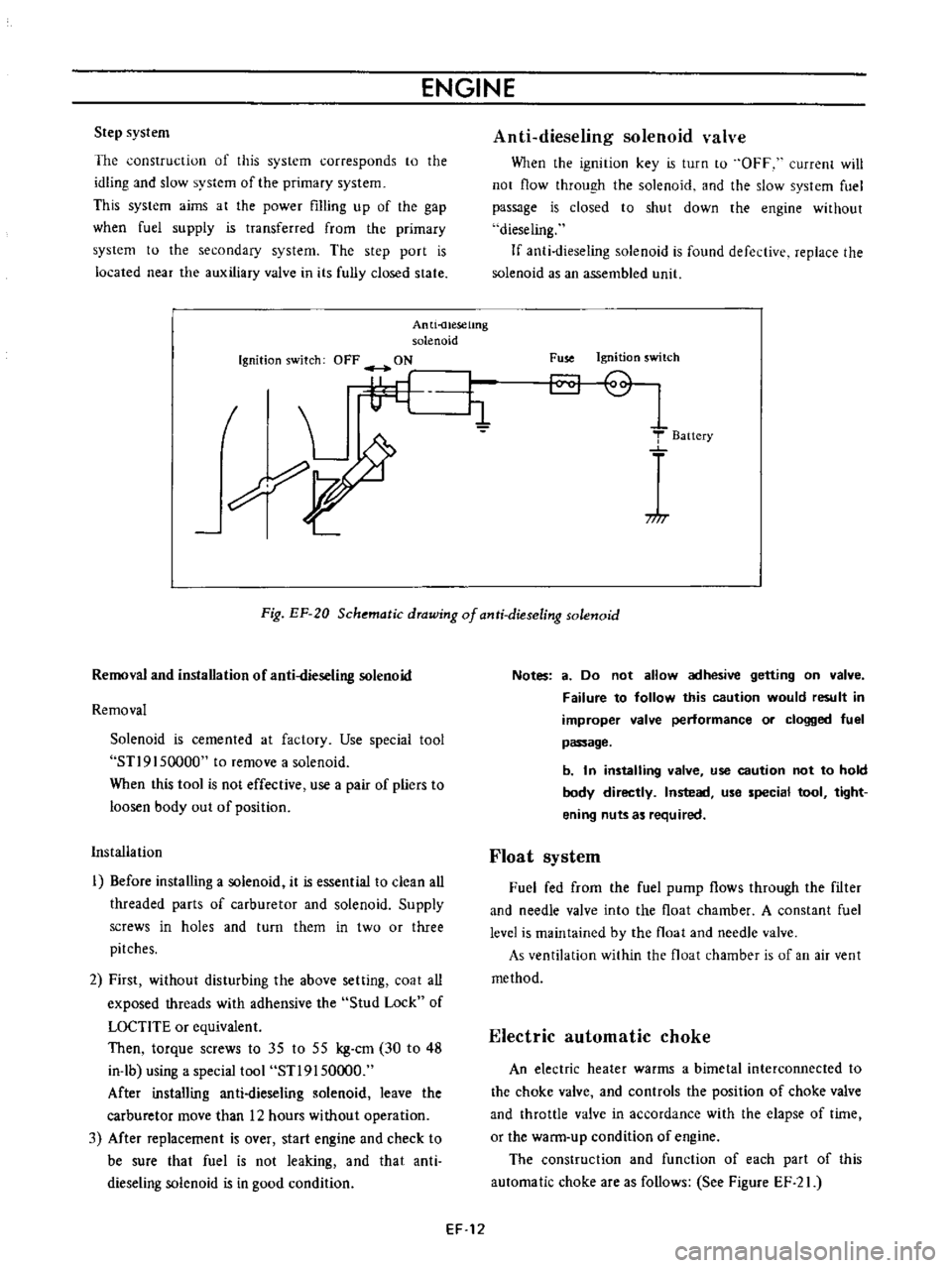
Anti
uesetmg
solenoid
Ignition
switch
OFF
ON
I
L
i1
7
I
Anti
dieseling
solenoid
valve
When
the
ignition
key
is
turn
to
OFF
current
will
not
flow
through
the
solenoid
and
the
slow
system
fuel
passage
is
closed
to
shut
down
the
engine
without
dieseling
If
anti
dieseling
solenoid
is
found
defective
replace
the
solenoid
as
an
assembled
llnit
Fuse
Ignition
switch
T
Baitery
717
Fig
EF
20
Schematic
drawing
of
anti
dieseling
solenoid
Removal
and
installation
of
anti
dieseling
solenoid
Removal
Solenoid
is
cemented
at
factory
Use
special
tool
STl9
I
50000
to
remove
a
solenoid
When
this
tool
is
not
effective
use
a
pair
of
pliers
to
loosen
body
out
of
position
Installation
I
Before
installing
a
solenoid
it
is
essential
to
clean
all
threaded
parts
of
carburetor
and
solenoid
Supply
screws
in
holes
and
turn
them
in
two
or
three
pitches
2
First
without
disturbing
the
above
setting
coat
all
exposed
threads
with
adhensive
the
Stud
Lock
of
LOCTlTE
or
equivalent
Then
torque
screws
to
35
to
55
kg
cm
30
to
48
in
lb
using
a
special
tool
STl9150000
After
installing
anti
dieseling
solenoid
leave
the
carburetor
move
than
12
hours
without
operation
3
Mter
replacement
is
over
start
engine
and
check
to
be
sure
that
fuel
is
not
leaking
and
that
anti
dieseling
solenoid
is
in
good
condition
Notes
a
Do
not
allow
adhesive
getting
on
valve
Failure
to
follow
this
caution
would
result
in
improper
valve
performance
or
clogged
fuel
passage
b
In
installing
valve
use
caution
not
to
hold
body
directly
Instead
use
special
tool
tight
ening
nuts
as
required
Float
system
Fuel
fed
from
the
fuel
pump
flows
through
the
filter
and
needle
valve
into
the
float
chamber
A
constant
fuel
level
is
maintained
by
the
float
and
needle
valve
As
ventilation
within
the
float
chamber
is
of
an
air
vent
method
Electric
automatic
choke
An
electric
heater
warms
a
bimetal
interconnected
to
the
choke
valve
and
controls
the
position
of
choke
valve
and
throttle
valve
in
accordance
with
the
elapse
of
time
or
the
warm
up
condition
of
engine
The
construction
and
function
of
each
part
of
this
automatic
choke
are
as
follows
See
Figure
EF
21
EF
12
Page 404 of 513
FUEl
SYSTEM
l
I
@
1J
w
I
I
I
I
1
1
1
t
2
3
4
5
6
7
8
9
10
tt
12
Hi
metal
Heater
Bi
metal
cover
Fast
idle
earn
Bi
metal
Bi
metal
index
mark
Choke
shaft
lever
Choke
valve
Unloader
tang
Vacuum
diaphragm
Throttle
valve
Fast
idle
adjusting
screw
j
@
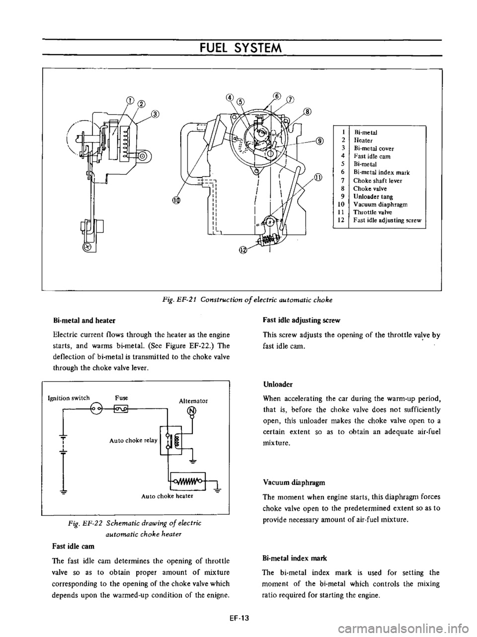
Fig
EP
21
Construction
of
electric
automatic
choke
Bi
metal
and
heater
Electric
current
flows
through
the
heater
as
the
engine
starts
and
warms
bi
metal
See
Figure
EF
22
The
deflection
of
bi
metal
is
transmitted
to
the
choke
valve
through
the
choke
valve
lever
Ignition
switch
Fuse
Alternator
T
o
o
Auto
choke
relay
Auto
choke
heater
Fig
EF
22
Schematic
drawing
of
electric
automatic
choke
heater
Fast
idle
C3m
The
fast
idle
cam
determines
the
opening
of
throttle
valve
so
as
to
obtain
proper
amount
of
mixture
corresponding
to
the
opening
of
the
choke
valve
which
depends
upon
the
warmed
up
condition
of
the
enigne
Fast
idle
adjusting
screw
This
screw
adjusts
the
opening
of
the
throttle
valve
by
fast
idle
cam
Unloader
When
accelerating
the
car
during
the
warm
up
period
that
is
before
the
choke
valve
does
not
sufficiently
open
this
unloader
makes
the
choke
valve
open
to
a
certain
extent
so
as
to
obtain
an
adequate
air
fuel
mixture
Vacuum
diaphragm
The
moment
when
engine
starts
this
diaphragm
forces
choke
valve
open
to
the
predetermined
extent
so
as
to
provide
necessary
amount
of
air
fuel
mixture
Bi
metaI
index
mark
The
bi
metal
index
mark
is
used
for
setting
the
moment
of
the
bi
metal
which
controls
the
mixing
ratio
required
for
starting
the
engine
EF
13
Page 405 of 513
ENGINE
AD
JUSTMENT
Idling
adjustment
Idle
mixture
adjustment
requires
the
use
of
a
CO
meter
When
preparing
to
adjust
idle
mixture
it
is
essential
to
have
the
meter
thoroughly
warmed
and
calibrated
Warm
up
the
engine
sufficiently
2
Continue
engine
operation
for
one
minute
under
idling
speed
3
Adjust
throttle
adjusting
screw
so
that
engine
speed
is
800
rpm
in
N
position
for
automatic
transmission
4
Check
ignition
timing
if
necessary
adjust
it
to
the
specifications
Ignition
timing
50
800
rpm
5
Adjust
idle
adjusting
screw
so
that
ca
percentage
is
1
5
t
0
5
6
Repeat
the
adjustments
as
described
in
steps
3
and
5
above
so
that
ca
percentage
is
1
5
to
5
at
800
rpm
Cautions
a
On
automatic
transmission
equipped
model
check
must
be
done
in
the
0
position
Be
sure
to
apply
parking
brake
and
to
lock
both
front
and
rear
wheels
with
wheel
chocks
b
Hold
brake
pedal
while
stepping
down
on
accelerator
pedal
Otherwise
car
will
rush
out
dangerously
7
On
automatic
transmission
equipped
model
make
sure
that
the
adjustment
has
been
made
with
the
selector
lever
in
N
position
And
then
check
the
specifications
with
the
lever
in
D
position
Insure
that
CO
percent
and
idle
speed
are
as
follows
Idle
rpm
650
ca
percentage
with
lever
in
D
position
15
to
5
If
necessary
adjust
by
progressively
turning
throttle
adjusting
screw
and
idle
adjusting
screw
until
correct
adjustments
are
made
Notes
a
Do
not
attempt
to
screw
down
the
id
Ie
adjusting
screw
completely
to
avoid
damage
to
the
EF
14
tip
which
will
tend
to
cause
malfunctions
b
After
idle
adjustment
has
been
made
shift
the
lever
to
N
or
p
position
for
automatic
transmission
c
Remove
wheel
chocks
before
starting
the
car
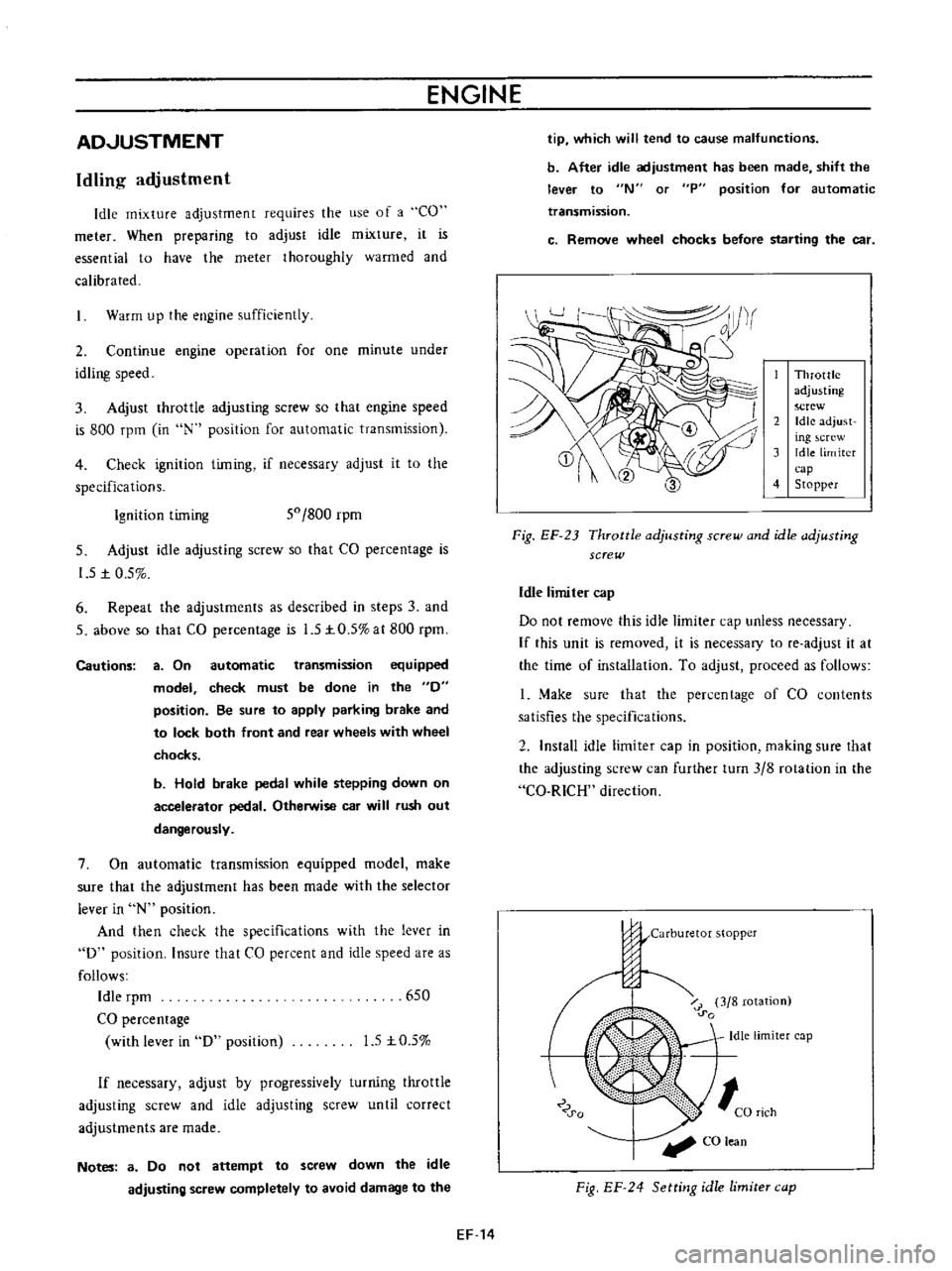
Throttle
adjusting
screw
2
Idle
adjust
ing
crew
3
Idle
limiter
cap
4
Stopp
r
Fig
EF
23
Throttle
adjusting
screw
and
idle
adjusting
screw
Idle
limiter
cap
Do
not
remove
this
idle
limiter
cap
unless
necessary
If
this
unit
is
removed
it
is
necessary
to
fe
adjust
it
at
the
time
of
installation
To
adjust
proceed
as
follows
1
Make
sure
that
the
percentage
of
CO
contents
satisfies
the
specifications
2
Install
idle
limiter
cap
in
position
making
sure
that
the
adjusting
screw
can
further
turn
3
8
rotation
in
the
Ca
RICH
direction
j
j
Carburetor
stopper
o
u
o
i
r
3
8
rotation
0
0
Idle
limiter
cap
0
0
CO
lean
Fig
EF
24
Setting
idle
limite
cap
Page 414 of 513
Troubles
Improper
idling
Rough
engine
idle
or
engine
stop
Engine
idle
too
fast
Engine
hesitation
FUEl
SYSTEM
Possible
causes
ruel
strainer
clogged
Vacuum
jet
clogged
Power
valve
operated
improperly
Slow
jet
clogged
Each
throttle
valve
does
not
close
Secondary
throttle
valve
operated
im
properly
Each
throttle
valve
shaft
wear
Packing
between
manifold
and
carburetor
defective
Fuel
overflows
Incorrect
carburetor
adjustment
idle
speed
idle
mixture
choke
setting
Incorrect
basic
ignition
timing
Incorrect
automatic
temperature
control
air
cleaner
Defect
or
malfunction
of
ignition
system
spark
plug
high
tension
cable
breaker
point
ignition
coil
etc
Trouble
in
throttle
link
and
cable
Incorrect
throttle
opener
adjustment
Trouble
in
PCV
valve
Trouble
in
automatic
choke
Defect
or
malfunction
of
ignition
system
spark
plug
high
tension
cable
breaker
point
ignition
coil
etc
Each
main
jet
slow
jet
clogged
By
pass
hole
idle
passage
clogged
Emulsion
tube
clogged
EF
23
Remedies
Clean
Clean
Adjust
Clean
Adjust
Overhaul
and
clean
Replace
Replace
tightening
See
the
first
item
Adjust
idle
speed
mixture
and
timing
Adjust
ignition
timing
Adjust
automatic
temperature
control
air
cleaner
Adjust
or
replace
ignition
system
Check
throttle
link
and
cable
Adjust
throttle
opener
Replace
PCV
valve
Adjust
auotmatic
choke
Adjust
or
replace
ignition
system
Clean
Clean
tube
Clean
Page 415 of 513
Troubles
Car
knock
when
coasting
Engine
does
not
start
ENGINE
Possible
causes
Idling
adjustment
incorrect
Secondary
throttle
valve
operated
im
properly
Incorrect
throttle
opener
adjustment
Trouble
in
PCV
valve
Defect
or
malfunction
of
ignition
system
spark
plug
high
tension
cable
breaker
point
ignition
coil
etc
Fuel
overflows
No
fu
el
Idling
adjustment
incorrect
Fast
idle
adjustment
incorrect
Damaged
anti
dieseling
solenoid
Bi
metal
rod
in
contact
with
hi
metal
case
EF
24
Remedies
Correct
adjustment
Overhaul
and
clean
Adjust
throttle
opener
Replace
PCV
valve
Adjust
or
replace
ignition
system
See
the
first
item
Check
pump
fuel
pipe
and
needle
valve
Correct
adjustment
Correct
adjustment
Replace
Adjust
Page 420 of 513
DATSUN
1200
MODEL
B
11
0
SERIES
L
NISSAN
I
NISSAN
MOTOR
CO
LTD
TOKYO
JAPAN
SECTION
EE
ENGINE
ELECTRICAL
SYSTEM
BATTERY
STARTING
MOTOR
CHARGING
CIRCUIT
ALTERNATOR
REGULATOR
IGNITIO
N
CIRCUIT
DISTRIBUTOR
IGNITION
COIL
SPARK
PLUG
EEl
EE
3
EE
15
EE
16
EE
23
EE
29
EE
29
EE
36
EE
37