1973 DATSUN B110 air condition
[x] Cancel search: air conditionPage 200 of 513
pointer
used
at
the
rearward
lut
atiol1
With
the
proper
scttings
the
tram
bar
will
be
on
a
piane
parallel
to
that
of
the
body
The
exception
to
this
would
be
wht
n
one
of
the
reterence
locations
is
induded
in
the
misaligned
area
then
the
parallel
plane
between
the
body
and
the
tram
bar
may
not
prevail
After
completiun
of
the
repairs
the
tram
gauge
should
be
set
at
the
specitled
dimension
to
check
the
accuracy
of
the
repair
operation
CAR
PREPARATION
Preparing
the
car
for
the
underbody
alignment
check
involves
the
following
Place
the
car
on
a
level
surface
2
The
weight
of
the
car
should
be
supported
at
the
wheel
locations
3
A
visual
damage
inspection
should
be
made
to
eliminate
unnecessary
measuring
Obviously
damaged
or
misaligned
areas
may
often
be
located
visually
BODY
TRAMMING
SEQUENCE
The
tramming
sequence
will
varv
depending
upon
the
nature
and
IOl
atiun
uf
the
misaligned
area
Priur
to
performing
any
tramming
uperation
the
h
uracy
of
refereJlce
points
to
be
used
must
be
determined
A
measurement
that
originates
from
a
reference
point
included
in
a
damaged
area
will
produce
untrue
results
and
confuse
the
evaluation
of
the
underbody
condition
Unlike
the
conventional
type
of
frame
design
the
unitized
type
of
body
construction
seldom
develops
the
condition
of
diamond
in
the
floor
pan
area
as
a
result
of
front
or
rear
end
collision
Therefore
underbody
alignment
checking
can
usually
originate
from
the
body
floor
pan
area
If
inspection
indicates
that
these
locations
have
been
disturbed
and
are
not
suitable
for
measuring
one
of
the
undamaged
suspension
locations
should
be
used
as
an
initial
reference
point
If
a
rare
situation
should
exist
where
all
of
these
lucalions
are
not
suitable
as
reference
points
repair
operations
should
begin
with
the
body
floor
pan
area
All
other
underbody
components
should
be
aligned
progressively
from
this
area
MEMO
BF
10
Page 247 of 513
BODY
PASSING
LIGHT
SWITCH
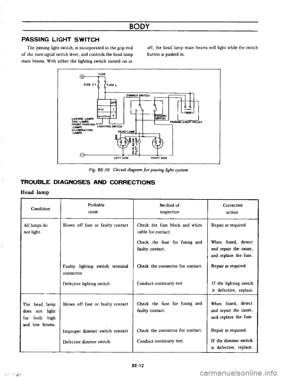
The
passing
light
switch
is
incorporated
in
the
grip
end
of
the
turn
signal
switch
lever
and
controls
the
head
lamp
main
beams
With
either
the
lighting
switch
turned
on
or
off
the
head
lamp
main
beams
will
light
while
the
switch
button
is
pushed
in
CB
FUSE
FUSE
P
T
FUSE
L
DI
TCH
ti
r
1
I
Y
fflf
0
00
0
2
ASSIHG
LICENSE
LAMPS
SWITCH
L
TAil
lAMPS
1
I
I
PASSING
LIGHT
RELAY
FRONT
PARKING
LAMPS
LIGHTING
SWITCH
1
NATlON
HEAD
lAMP
nt
OF
LEFT
sIDe
RIGtfT
SIDE
Fig
BE
30
Circuit
diagram
for
passing
light
system
TROUBLE
DIAGNOSES
AND
CORRECTIONS
Head
lamp
Probable
Me
thod
of
Condition
inspection
cause
All
lamps
do
not
light
Blown
off
fuse
or
faulty
contact
Check
the
fuse
block
and
white
cable
for
contact
Check
the
fuse
for
fusing
and
faulty
contact
Faulty
lighting
switch
terminal
connector
Check
the
connector
for
contact
Defective
lighting
switch
Conduct
continuity
test
The
head
lamp
Blown
off
fuse
or
faulty
contact
does
not
light
for
both
high
and
low
beams
Check
the
fuse
for
fusing
and
faulty
contact
Improper
dimmer
switch
contact
Check
the
connector
for
contact
Defective
dimmer
switch
Conduct
continuity
test
BE
12
r
Corrective
action
Repair
as
required
When
fused
detect
and
repair
the
cause
and
replace
the
fuse
Repair
as
required
If
the
ligh
ting
swi
tch
is
defective
replace
When
fused
detect
and
repair
the
cause
and
replace
the
fuse
Repair
as
required
I
f
the
dimmer
switch
is
defective
replace
Page 248 of 513
BODY
ELECTRICAL
Main
high
beam
Defective
dimmer
switch
cannot
be
switch
ed
to
dimmer
low
beam
or
vice
versa
Head
lamps
dim
Defective
light
circuit
Head
lamps
dim
Partly
discharged
battery
when
the
engine
is
stopped
or
op
era
ted
under
idling
speed
Defective
battery
Head
lamps
still
Faulty
sealed
beam
unit
dim
with
engine
run
above
idling
speed
Faulty
charging
system
Head
light
in
only
one
side
lights
Faulty
head
lamp
terrnianl
con
tact
Defective
lamp
Turn
signal
lamps
Probable
Condition
cause
All
turn
signal
Blown
fuse
or
faulty
contact
lamps
do
not
light
When
red
yellow
cable
is
con
nected
to
red
white
cable
or
red
black
cable
and
the
main
beam
or
dimmer
beam
lights
the
circuit
is
nonnal
The
dimmer
switch
is
defective
Check
the
head
light
circuit
for
cable
being
about
to
break
and
faulty
contact
or
check
fuse
for
faulty
contact
Measure
specific
gravity
of
elec
trolyte
Voltage
between
head
lamp
red
white
cable
and
red
cable
ter
minals
is
12
8V
or
higher
Voltage
is
less
than
12
8V
through
above
test
Method
of
inspection
Check
the
fuse
for
fusing
and
faulty
contact
BE
13
Conduct
continuity
test
and
if
the
dirn
mer
switch
is
defec
tive
replace
Repair
or
replace
if
required
Charge
battery
if
required
Replace
battery
Replace
sealed
beam
units
Check
the
generator
regulator
and
light
circuit
Repair
as
required
Replace
lamp
Corrective
action
When
the
fuse
is
fused
detect
and
repair
the
cause
and
replace
the
fuse
Page 250 of 513
Flashing
cycle
varies
BODY
ELECTRICAL
Faulty
contact
of
power
supply
circuit
from
ignition
switch
to
fuse
Tail
and
stop
lamp
license
lamp
back
up
lamp
Condition
Both
left
and
right
lamps
do
not
light
Probable
cause
Blown
off
fuse
or
faulty
contact
Defective
stop
larnp
switch
or
backup
lamp
switch
or
faulty
contact
Stop
larnps
and
backup
lamp
only
Faulty
grounding
Only
one
side
lamp
Burnt
out
lamp
bulb
f1lament
lights
Brightness
of
one
side
lamp
differs
from
the
other
HORN
Removal
Adjustment
Faulty
contact
of
connector
ter
minal
and
or
socket
Faulty
contact
of
connector
ter
minal
and
or
socket
BE
16
BE
16
BE
16
When
the
windshield
wiper
which
uses
the
ignition
for
power
supply
is
operated
flashing
cycle
and
brightness
change
Method
of
inspection
Check
the
fuse
for
fusing
and
faulty
contact
When
two
lead
wires
of
the
switch
are
connected
and
the
lamp
lights
the
larnp
and
circuit
are
normal
All
rear
combination
lamps
do
not
light
HORN
CONTENTS
TROUBLE
DIAGNOSES
AND
CORRECTIONS
BE
15
Repair
as
required
Corrective
action
When
the
fuse
is
fused
detect
and
COf
rect
the
cause
and
replace
the
fuse
Replace
the
switch
or
repair
the
connector
terrninal
Repair
the
grounding
cable
contact
Replace
the
larnp
with
a
new
one
Repair
or
replace
Repair
or
replace
if
required
BE
17
Page 252 of 513
BODY
ELECTRICAL
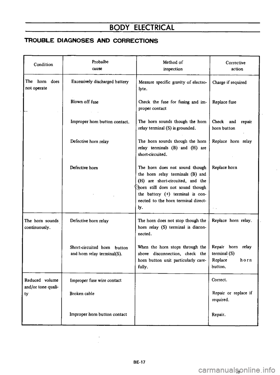
TROUBLE
DIAGNOSES
AND
CORRECTIONS
Condition
The
horn
does
not
operate
The
horn
sounds
continuously
Reduced
volume
and
or
tone
quali
ty
Probalbe
cause
Excessively
discharged
battery
Blown
off
fuse
Improper
horn
button
contact
Defective
horn
relay
Defective
horn
Defective
horn
relay
Short
circuited
horn
button
and
horn
relay
terminal
S
Improper
fuse
wire
contact
Broken
cable
Improper
horn
button
contact
Method
of
inspection
Measure
specific
gravity
of
electro
lyte
Corrective
action
Charge
if
required
Check
the
fuse
for
fusing
and
im
Replace
fuse
proper
contact
The
horn
sounds
though
the
horn
relay
terrninal
S
is
grounded
Check
and
repair
horn
button
The
horn
sounds
though
the
horn
Replace
horn
relay
relay
terrninals
B
and
H
are
short
circuited
The
horn
does
not
sound
though
Replace
horn
the
horn
relay
terminals
B
and
H
are
short
circuited
and
the
porn
still
does
not
sound
though
the
battery
terminal
is
con
nected
to
the
horn
terminal
direct
ly
The
horn
does
not
stop
though
the
Replace
horn
relay
horn
relay
S
terminal
is
discon
nected
When
the
horn
stops
through
the
above
disconnection
check
the
horn
button
unit
particularly
care
fully
BE
17
Repair
horn
relay
terminal
S
Replace
horn
button
Correct
Repair
or
replace
if
required
Repair
d
Page 258 of 513
BODY
ELECTRICAL
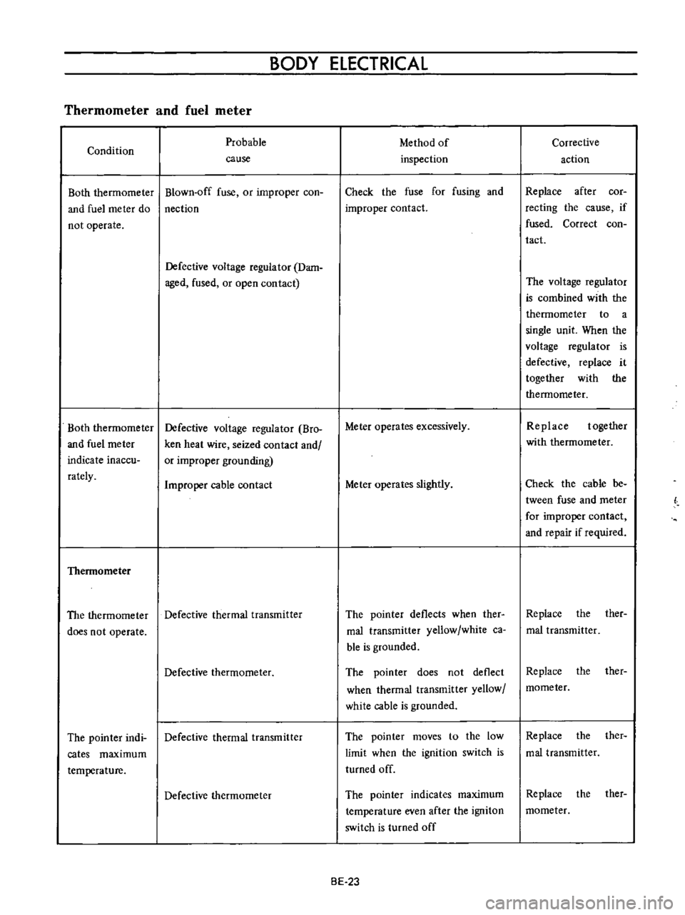
Thermometer
and
fuel
meter
Condition
Both
therrnorneter
and
fuel
rneter
do
not
operate
Both
thermorneter
and
fuel
rneter
indicate
inaccu
rately
Thennometer
Probable
cause
Blown
off
fuse
or
improper
coo
nection
Defective
voltage
regulator
Dam
aged
fused
or
open
contact
Defective
voltage
regulator
Bro
ken
heat
wire
seized
contact
and
or
improper
grounding
Improper
cable
contact
The
thermometer
Defective
thermal
transmitter
does
not
operate
Defective
thermometer
The
pointer
indi
Defective
thermal
transmitter
cates
maximum
temperature
Defective
thermometer
Method
of
inspection
Check
the
fuse
for
fusing
and
improper
contact
Meter
operates
excessively
Meter
operates
slightly
The
pointer
deflects
when
ther
mal
transrnitter
yellow
white
ca
ble
is
grounded
The
pointer
does
not
deflect
when
thermal
transmitter
yellow
white
cable
is
grounded
The
pointer
moves
to
the
low
limit
when
the
ignition
switch
is
turned
off
The
pointer
indicates
maximum
temperature
even
after
the
ignitoD
switch
is
turned
off
BE
23
Corrective
action
Replace
after
cor
recting
the
cause
if
fused
Correct
coo
tact
The
voltage
regulator
is
combined
with
the
thermometer
to
a
single
unit
When
the
voltage
regulator
is
defective
replace
it
together
with
the
thermometer
Replace
together
with
thermometer
Check
the
cable
be
tween
fuse
and
meter
for
improper
contact
and
repair
if
required
Replace
the
ther
mal
transmitter
Replace
the
ther
mometer
Replace
the
ther
mal
transmitter
Replace
the
ther
mometer
Page 260 of 513

BODY
ELECTRICAL
Improper
cable
contact
Oil
pressure
and
ignition
warning
lamps
Condition
Oil
pressure
Want
ing
lamp
The
lamp
does
not
ligh
t
when
the
ignition
switch
is
set
to
ON
Probable
cause
Blown
off
fuse
or
faulty
contact
Broken
lamp
bulb
fIlarnent
or
faulty
cable
contact
Defective
oil
pressure
switch
The
lamp
does
not
Oil
pressure
is
too
low
go
out
while
the
engine
is
being
operated
Lack
of
engine
oil
Defective
oil
pressure
switch
Ignition
warning
lamp
The
lamp
does
not
light
when
the
ignition
switch
is
set
to
ON
Blown
off
fuse
or
faulty
contact
Burnt
out
light
bulb
filarnent
or
faulty
cable
contact
The
fuel
rneter
indicates
a
level
slightly
lower
than
the
actual
level
Method
of
inspection
Check
the
fuse
for
fusing
and
faulty
contact
The
warning
lamp
does
not
light
when
oil
pressure
switch
yellow
black
cable
is
grounded
The
warning
lamp
lights
through
the
above
inspection
Inspect
the
engine
oil
pressure
system
Check
oil
level
Continuity
exists
on
the
oil
pres
sure
switch
when
the
engine
is
being
operated
Check
the
fuse
for
fusing
and
faulty
contact
The
pilot
lamp
does
not
light
when
the
voltage
regulator
con
nector
is
disconnected
the
white
red
cable
is
grounded
and
the
ignition
switch
is
set
to
ON
BE
25
Check
the
cable
from
the
fuel
meter
to
the
tank
unit
for
cable
being
about
to
break
poor
contact
and
faulty
grounding
and
repair
as
required
Corrective
action
Replace
after
corree
ting
the
fuse
the
cause
if
fused
Check
the
light
bulb
for
burnt
out
fIla
ment
and
replace
as
required
Replace
the
oil
pres
sure
switch
Add
oil
Replace
the
oil
pres
sure
switch
Repair
or
replace
as
required
Check
the
bulb
for
burnt
out
fIlament
and
replace
as
re
quired
Page 263 of 513
BODY
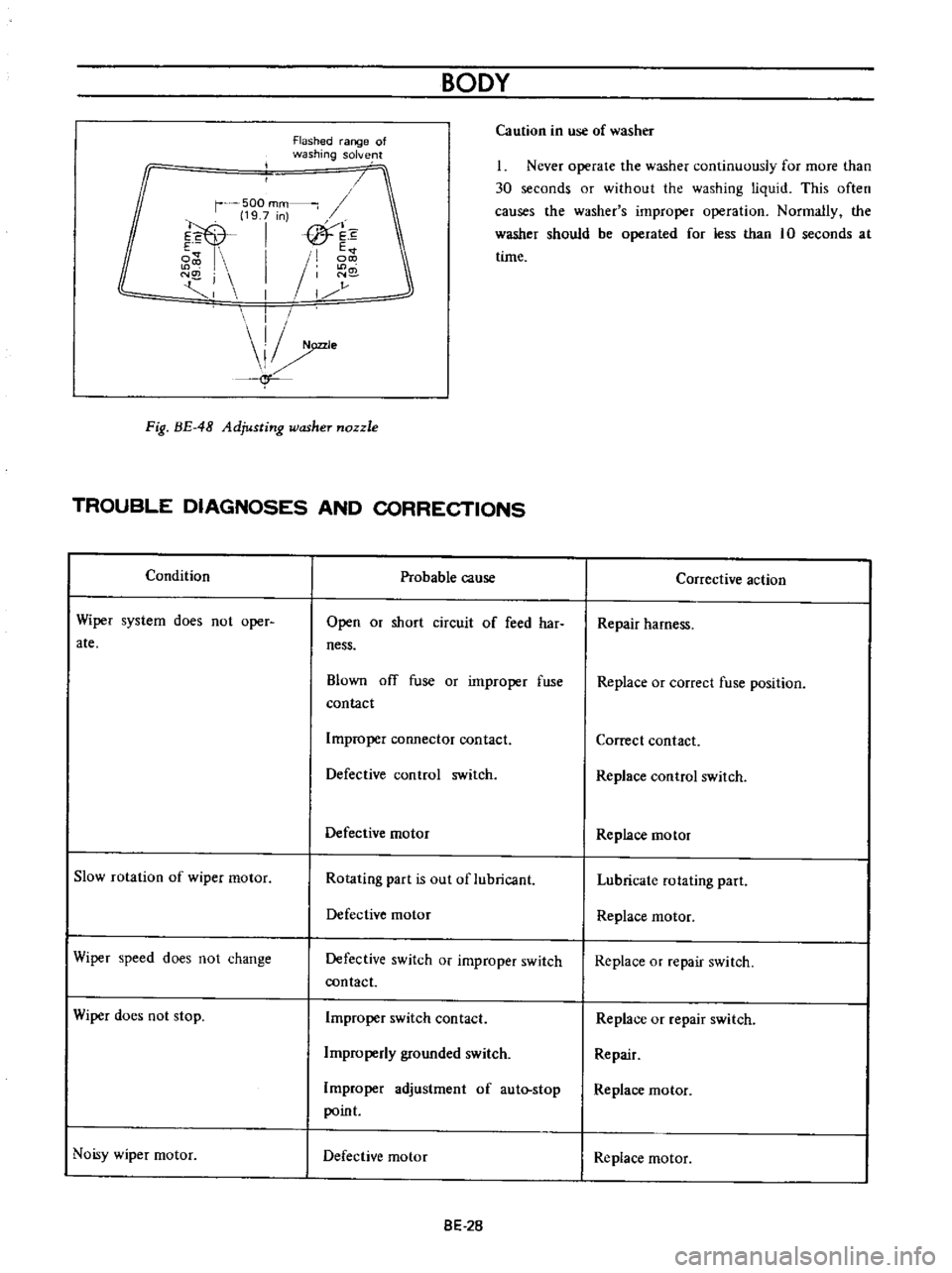
Flashed
range
of
washing
solve
lt
Ca
ution
in
use
of
washer
r
500
mm
19
7
n
E
I
fTh
e
i
E
I
I
N
j
1
N
I
1
r
j
I
I
e
f
1
Never
operate
the
washer
continuously
for
more
than
30
seconds
or
without
the
washing
liquid
This
often
causes
the
washer
s
improper
operation
Normally
the
washer
should
be
operated
for
less
than
10
seconds
at
time
Fig
BE
48
Adjusting
washer
nozzle
TROUBLE
DIAGNOSES
AND
CORRECTIONS
Condition
Probable
cause
Corrective
action
Wiper
system
does
not
oper
ate
Open
or
short
circuit
of
feed
har
ness
Repair
harness
Blown
ofT
fuse
or
improper
fuse
contact
Replace
or
correct
fuse
position
Improper
connector
contact
Correct
contact
Defective
control
switch
Replace
control
switch
Defective
motor
Replace
motor
Slow
rotation
of
wiper
motor
Rotating
part
is
out
of
lubricant
Lubricate
rotating
part
Defective
motor
Replace
rnotor
Wiper
speed
does
not
change
Defective
switch
or
improper
switch
contact
Replace
or
repair
switch
Wiper
does
not
stop
Improper
switch
contact
Replace
or
repair
switch
Irnproperly
grounded
switch
Repair
Improper
adjustment
of
aut
stop
point
Replace
motor
Noisy
wiper
motor
Defective
motor
Replace
motor
8E
2B