1973 DATSUN B110 air condition
[x] Cancel search: air conditionPage 439 of 513
ENGINE
ELECTRICAL
SYSTEM
Note
Use
care
in
handling
diode
assembly
to
prevent
an
undue
stress
on
it
INSPECTION
AND
REPAIR
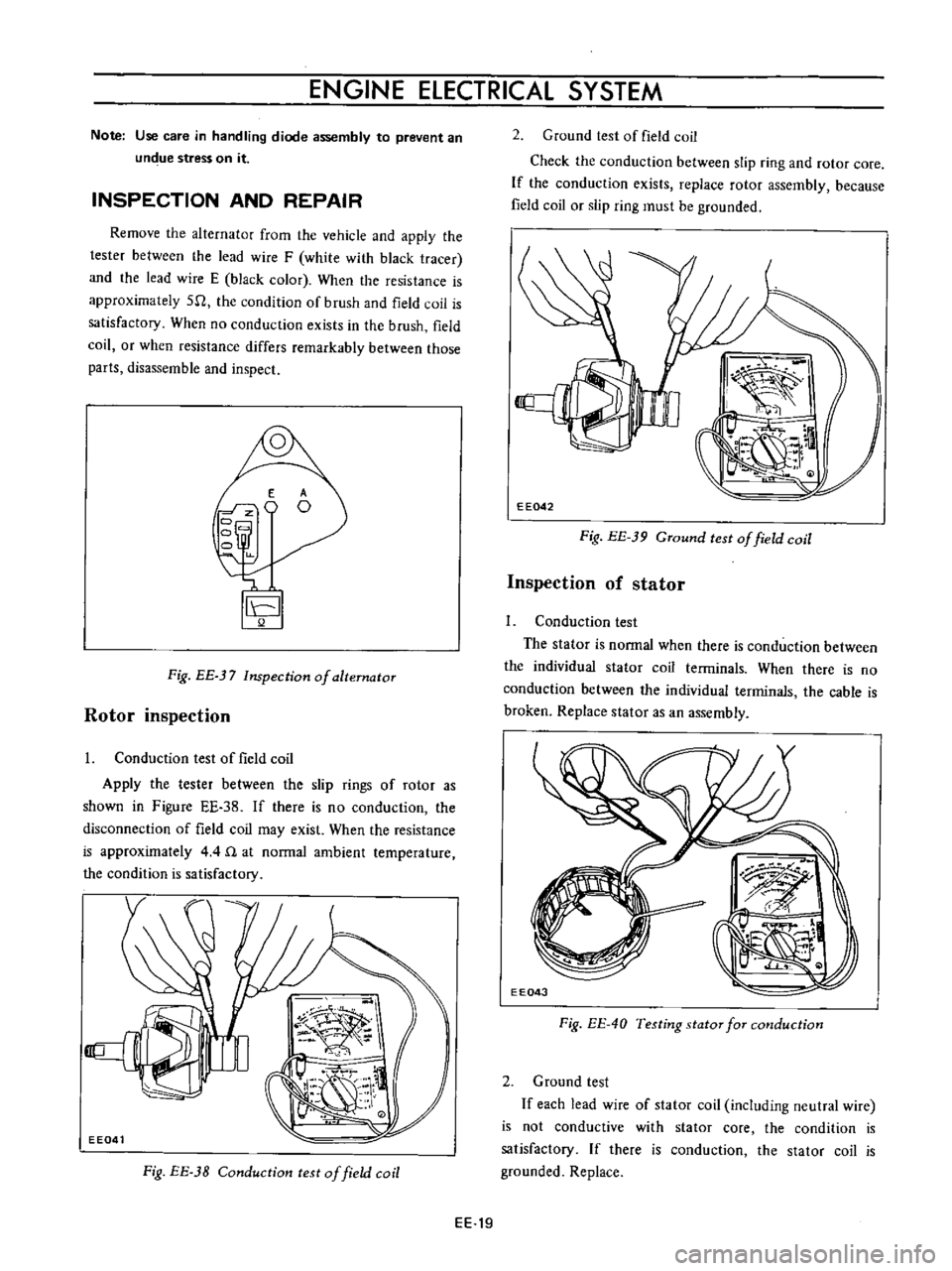
Remove
the
alternator
from
the
vehicle
and
apply
the
tester
between
the
lead
wire
F
white
with
black
tracer
and
the
lead
wire
E
black
color
When
the
resistance
is
approximately
511
the
condition
of
brush
and
field
coil
is
satisfactory
When
no
conduction
exists
in
the
brush
field
coil
or
when
resistance
differs
remarkably
between
those
parts
disassemble
and
inspect
E
o
Fig
BE
37
Inspection
of
alternator
Rotor
inspection
I
Conduction
test
of
field
coil
Apply
the
tester
between
the
slip
rings
of
rotor
as
shown
in
Figure
EE
38
If
there
is
no
conduction
the
disconnection
of
field
coil
may
exist
When
the
resistance
is
approximately
4
4
n
at
normal
ambient
temperature
the
condition
is
satisfactory
Fig
EE
3B
Conduction
test
of
field
coil
2
Ground
test
of
field
coil
Check
the
conduction
between
slip
ring
and
rotor
core
If
the
conduction
exists
replace
rotor
assembly
because
field
coil
or
slip
ring
must
be
grounded
EE042
Fig
EE
39
GTound
test
of
field
coil
Inspection
of
stator
1
Conduction
test
The
stator
is
normal
when
there
is
conduction
between
the
individual
stator
coil
terminals
When
there
is
no
conduction
between
the
individual
terminals
the
cable
is
broken
Replace
stator
as
an
assembly
EE043
Fig
EE
40
Testing
stator
for
cmlduction
2
Ground
test
If
each
lead
wire
of
stator
coil
including
neutral
wire
is
not
conductive
with
stator
core
the
condition
is
satisfactory
If
there
is
conduction
the
stator
coil
is
grounded
Replace
EE
19
Page 444 of 513
ENGINE
MEASUREMENT
OF
REGULATING
VOLTAGE
The
regulator
voltage
is
measured
with
the
alternator
When
measuring
voltage
with
regulator
mounted
on
vehicle
it
is
necessary
to
rotate
engine
at
high
speed
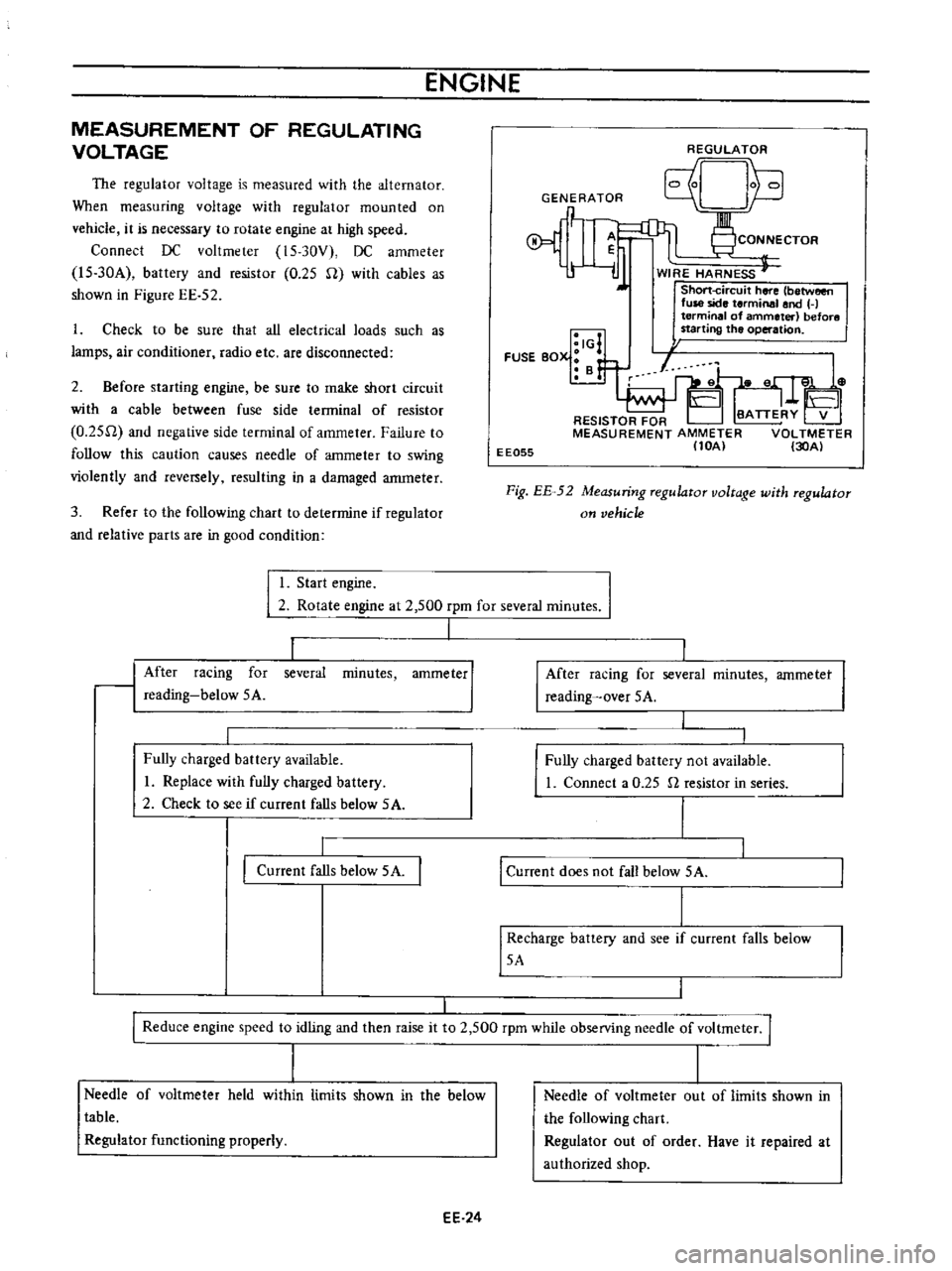
Connect
DC
voltmeter
15
30V
DC
ammeter
l5
30A
battery
and
resistor
0
25
U
with
cables
as
shown
in
Figure
EE
52
1
Check
to
be
sure
that
all
electrical
loads
such
as
lamps
air
conditioner
radio
etc
are
disconnected
2
Before
starting
engine
be
sure
to
make
short
circuit
with
a
cable
between
fuse
side
terminal
of
resistor
O
25U
and
negative
sIde
terminal
of
ammeter
Failure
to
follow
this
caution
causes
needle
of
ammeter
to
swing
violently
and
rever
ely
resulting
in
a
damaged
anuneter
3
Refer
to
the
following
chart
to
determine
if
regulator
and
relative
parts
are
in
good
condition
REGULATOR
Unh
GENERATOR
q
P
1
CONNECTOR
r
l
ij
WIRE
HARNESS
J
Short
circuit
here
between
fuse
side
terminal
and
H
terminal
of
ammeter
before
starting
the
operation
I
I
I
IG
FUSE
BOX
B
f
EE055
Fig
EE
52
Measuring
regulator
voltage
with
regulator
on
vehicle
I
Start
engine
I
2
Rotate
engine
at
2
500
rpm
for
several
minutes
I
1
minutes
ammeter
I
After
racing
for
reading
below
5A
several
Fully
charged
battery
available
I
Replace
with
fully
charged
battery
2
Check
to
see
if
current
falls
below
5A
Current
falls
below
5A
I
After
racing
for
several
reading
over
5A
minutes
ammetet
I
Fully
charged
battery
not
available
1
Connect
a
0
25
n
resistor
in
series
I
Current
does
not
fall
below
5A
I
Recharge
battery
and
see
if
current
falls
below
5A
I
I
Reduce
engine
speed
to
idling
and
then
raise
it
to
2
500
rpm
while
observing
needle
of
voltmeter
I
I
I
Needle
of
voltmeter
held
within
limits
shown
in
the
below
table
Regulator
functioning
properly
EE
24
Needle
of
voltmeter
out
of
limits
shown
in
the
following
chart
Regulator
out
of
order
Have
it
repaired
at
authorized
shop
Page 457 of 513
ENGINE
ElECTRICAL
SYSTEM
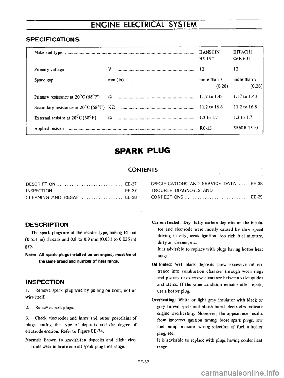
SPECIFICATIONS
Make
and
type
Primary
voltage
v
Spark
gap
mm
in
Primary
resistance
at
200C
680
F
n
Secondary
resistance
at
200C
680F
Kn
External
resistor
at
200C
680
F
n
Applied
resistor
HANSHIN
HITACHI
H5
15
2
C6R
601
12
12
more
than
7
more
than
7
0
28
0
28
1
17
to
I
43
l
l
7
to
I
43
11
2
to
16
8
11
2
to
16
8
l
3tol7
l
3tol7
RC
15
5560R
151O
SPARK
PLUG
CONTENTS
DESCRIPTION
INSPECTION
CLEANING
AND
REGAP
EE
37
EE
37
EE
38
DESCRIPTION
The
spark
plugs
are
of
the
resister
type
having
14
mm
0
551
in
threads
and
0
8
to
0
9
mm
0
031
to
0
Q35
in
gap
Note
All
spark
plugs
installed
on
an
engine
must
be
of
the
same
brand
and
number
of
heat
range
INSPECTION
1
Remove
spark
plug
wire
by
pulling
on
boot
not
on
wire
itself
2
Remove
spark
plugs
3
Check
electrodes
and
inner
and
outer
porcelains
of
plugs
noting
the
type
of
deposits
and
the
degree
of
electrode
erosion
Refer
to
Figure
EE
74
Normal
Brown
to
grayish
tan
deposits
and
slight
elec
trode
wear
indicate
correct
spark
plug
heat
range
SPECIFICATIONS
AND
SERVICE
DATA
TROUBLE
DIAGNOSES
AND
CORRECTIONS
EE
38
EE
39
Carbon
fouled
Dry
fluffy
carbon
deposits
on
the
insula
tor
and
electrode
were
mostly
caused
by
slow
speed
driving
in
city
weak
ignition
too
rich
fuel
mixture
dirty
air
cleaner
etc
H
is
advisable
to
replace
with
plugs
having
hotter
heat
range
Oil
fouled
Wet
black
deposits
show
excessive
oil
en
trance
into
combustion
chamber
through
worn
rings
and
pistons
or
excessive
clearance
between
valve
guides
and
stems
If
the
same
condition
remains
after
repair
use
a
hotter
plug
Overheating
White
or
light
gray
insulator
with
black
or
gray
brown
spots
and
bluish
burnt
electrodes
indicate
engine
overheating
Moreover
the
appearance
results
from
incorrect
ignition
timing
loose
spark
plugs
low
fuel
pump
pressure
wrong
selection
of
fuel
a
hotter
plug
etc
H
is
advisable
to
replace
with
plugs
having
colder
heat
range
EE
37
Page 459 of 513

ENGINE
ELECTRICAL
SYSTEM
TROUBLE
DIAGNOSES
AND
CORRECTIONS
When
engine
does
not
start
If
there
is
no
trouble
in
fuel
system
ignition
system
should
be
checked
This
can
be
easily
done
by
detaching
a
high
tension
cable
from
spark
plug
starting
engine
and
observing
condition
of
spark
that
occurs
between
high
tension
cable
and
spark
plug
terminal
After
checking
this
repair
as
necessary
Length
of
Trouble
location
Cause
Remedies
spark
gap
No
sparks
at
all
Distributor
Defective
insulation
of
condenser
Replace
Breakage
of
lead
wire
on
low
tension
side
Repair
Defective
insulation
of
cap
and
rotor
head
Replace
Point
does
not
open
or
close
Repair
Ignition
coil
Wire
breakage
or
short
circuit
of
coil
Replace
with
new
one
High
tension
cable
Wire
coming
off
Repair
Defective
insulation
Replace
I
to
2
mm
0
0394
Distributor
Point
gap
too
wide
Correct
to
0
0787
in
or
Oil
sticking
on
point
Clean
irregular
Point
burnt
too
much
Replace
Less
than
6
mm
Spark
plugs
Electrode
gap
too
wide
Correct
or
replace
0
2362
in
Too
much
carbon
Clean
or
replace
Broken
neck
of
insulator
Replace
Expiry
of
plug
life
Replace
2
When
engine
rotates
but
does
not
run
smoothly
In
this
case
there
are
many
causes
resulting
from
the
ignition
system
and
other
engine
conditions
not
related
to
ignition
Therefore
first
complete
inspection
of
ignition
system
should
be
carried
out
EE
39
Page 473 of 513
CLUTCH
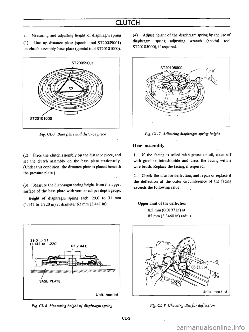
2
Measuring
and
adjusting
height
of
diaphragm
spring
I
Line
up
distance
piece
special
tool
ST20059001
on
clutch
assembly
base
plate
special
tool
ST20101O
0
ST20059001
I
ST20101000
Fig
CL
5
Base
plate
and
distance
piece
2
Place
the
clutch
assembly
on
the
distance
piece
and
set
the
clutch
assembly
on
the
base
plate
stationarily
Under
this
condition
the
distance
piece
is
placed
beneath
the
pressure
plate
3
Measure
the
diaphragm
spring
height
from
the
upper
surface
of
the
base
plate
with
vernier
caliper
depth
gauge
Height
of
diaphragm
spring
end
29
0
to
31
mm
1
142
to
1
220
in
at
diameter
62
mm
2
441
in
29
0
to
31
It
142
to
1
2201
6212
44
t
r
1
G
L
ir
I
LJIlW
I
y
y
x
l
i
0
BASE
PLATE
Unit
mm
in
Fig
CL
6
Measuring
height
of
dio
phTagm
spTing
4
Adjust
height
of
the
diaphragm
spring
by
the
use
of
diaphragm
spring
adjusting
wrench
special
tool
ST20
1
05000
if
required
Fig
CL
7
Adjusting
dio
phTagm
spring
height
Disc
assembly
If
the
facing
is
soiled
with
grease
or
oil
clean
off
with
gasoline
tetracWoride
and
dress
the
facing
with
a
wire
brush
Replace
the
facing
if
required
2
Check
the
disc
for
deflection
and
repair
or
replace
if
the
deflection
at
the
outer
circumference
of
the
facing
exceeds
the
following
value
Upper
limit
of
the
deflection
0
5
mm
0
0197
in
at
85
mm
3
3460
in
radius
Unit
mm
in
Fig
CL
8
Checking
disc
fOT
deflection
CL
3
Page 476 of 513
CHASSIS
fulcrum
type
The
mechanical
type
clutch
control
system
consists
of
pendent
clutch
pedal
clutch
control
cable
and
with
drawallever
The
withdrawal
lever
is
of
an
outer
fulcrum
type
which
provides
a
great
lever
ratio
and
thus
force
required
in
depressing
clutch
pedal
is
reduced
CLUTCH
PEDAL
Hydraulic
clutch
Removal
Remove
the
return
spring
2
Loosen
the
lock
nut
of
the
master
cylinder
push
rod
and
disconnect
the
push
rod
end
3
Remove
the
lock
nut
and
washer
of
the
pedal
shaft
and
remove
the
pedal
lever
Inspection
Thoroughly
clean
all
disassembled
parts
indicated
below
and
carefully
check
them
for
wear
damage
and
other
abnormal
conditions
Repair
or
replace
them
with
new
ones
if
required
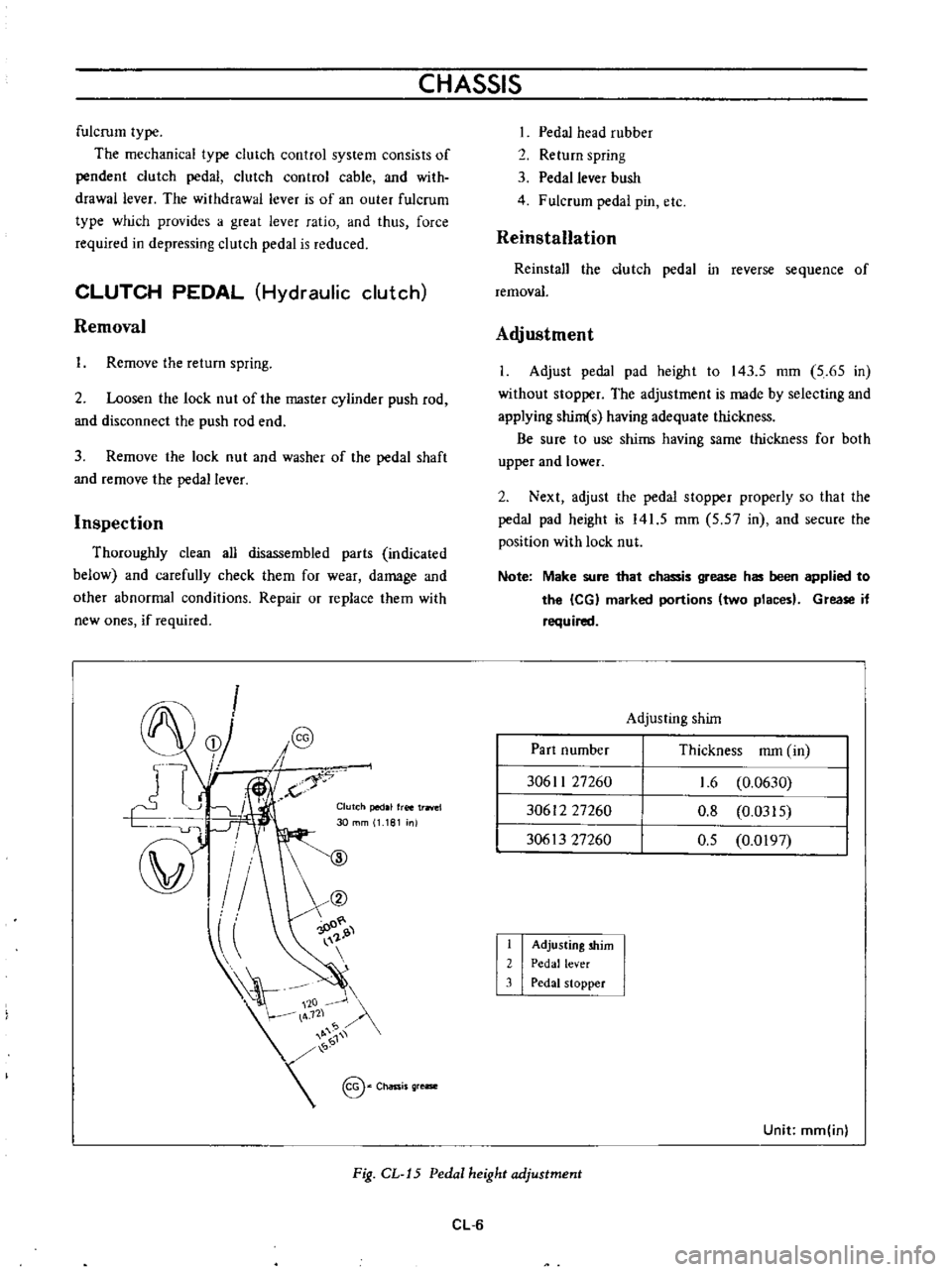
f
fS
C5
J
dJ
YII
10
1
@
c
i
@
j
1
4
K
Clutch
pedal
free
trrlel
30
mm
1
181
nl
00
@
P
IO
Pedal
head
rubber
2
Return
spring
3
Pedal
lever
bush
4
Fulcrum
pedal
pin
etc
Reinstallation
Reinstall
the
clutch
pedal
in
reverse
sequence
of
removal
Adjustment
I
Adjust
pedal
pad
height
to
143
5
mm
5
65
in
without
stopper
The
adjustment
is
made
by
selecting
and
applying
shim
s
having
adequate
thickness
Be
sure
to
use
shims
having
same
thickness
for
both
upper
and
lower
2
Next
adjust
the
pedal
stopper
properly
so
that
the
pedal
pad
height
is
141
5
mm
5
57
in
and
secure
the
position
with
lock
nut
Note
Make
sure
that
chassis
grease
has
been
applied
to
the
leG
marked
portions
two
places
Grease
if
required
Adjusting
shim
Part
number
Thickness
mm
in
30611
27260
30612
27260
30613
27260
1
6
0
0630
0
8
0
0315
0
5
0
0197
I
2
3
Adjusting
shim
Pedal
lever
Pedal
stopper
Unit
mm
inl
Fig
CL
J5
Pedal
height
adjustment
CL
6
Page 477 of 513
CLUTCH
CLUTCH
PEDAL
AND
CLUTCH
CONTROL
CABLE
Mechanical
clutch
Removal
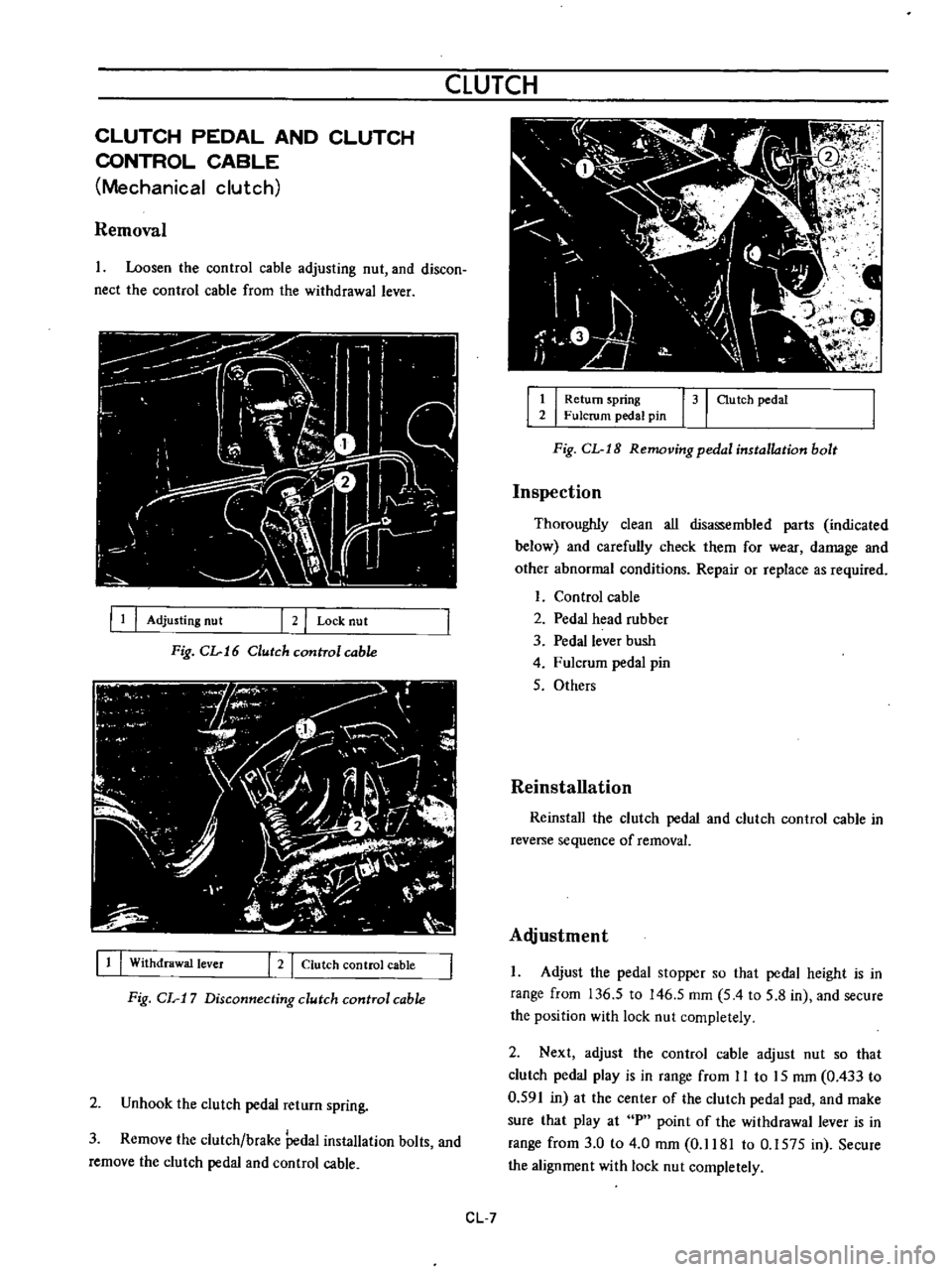
Loosen
the
control
cable
adjusting
nut
and
discon
nect
the
control
cable
from
the
withdrawal
lever
III
Adjusting
nut
2
I
Lock
nut
Fig
CL
16
Clutch
cunITol
cable
11
I
Withdrawal
lever
I
2
I
Clutch
control
cable
Fig
CL
17
Disconnecting
clutch
control
cable
2
Unhook
the
clutch
pedal
return
spring
3
Remove
the
clutch
brake
Pedal
installation
bolts
and
remove
the
clutch
pedal
and
control
cable
1
I
Return
spring
31
au
tch
pedal
2
Fulcrum
pedal
pin
Fig
CL
I8
Removing
pedal
installation
bolt
Inspection
Thoroughly
clean
all
disassembled
parts
indicated
below
and
carefully
check
them
for
wear
damage
and
other
abnormal
conditions
Repair
or
replace
as
required
Control
cable
2
Pedal
head
rubber
3
Pedal
lever
bush
4
Fulcrum
pedal
pin
5
Others
Reinstallation
Reinstall
the
clutch
pedal
and
clutch
control
cable
in
reverse
sequence
of
removal
Alljustment
Adjust
the
pedal
stopper
so
that
pedal
height
is
in
range
from
136
5
to
146
5
mm
5
4
to
5
8
in
and
secure
the
position
with
lock
nut
completely
2
Next
adjust
the
control
cable
adjust
nut
so
that
clutch
pedal
play
is
in
range
from
II
to
15
mm
0
433
to
0
591
in
at
the
center
of
the
clutch
pedal
pad
and
make
sure
that
play
at
P
point
of
the
withdrawal
lever
is
in
range
from
3
0
to
4
0
mm
0
1181
to
0
1575
in
Secure
the
alignment
with
lock
nut
completely
CL
7
Page 494 of 513
TRANSMISSION
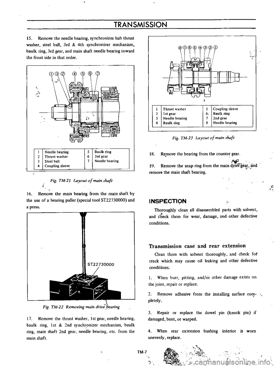
15
Remove
the
needle
bearing
synchronizer
hub
thrust
washer
steel
ball
3rd
4th
synchronizer
mechanism
baulk
ring
3rd
gear
and
main
shaft
needle
bearing
toward
the
front
side
in
that
order
S
b
L
74FE
r
1
Needle
bearing
2
Thrust
washer
3
Steel
ball
4
Coupling
sleeve
5
BauIk
ring
6
3rd
gear
7
Needle
bearing
Fig
TM
21
Layout
of
main
shaft
16
Remove
the
main
bearing
from
the
main
shaft
by
the
use
of
a
bearing
puller
special
tool
ST2273
000
and
a
press
1
ST22730000
r
1
t
Jii
Fig
TM
22
Removing
main
drive
l7earing
17
Remove
the
thrust
washer
I
st
gear
needle
bearing
baulk
ring
1st
2nd
synchronizer
mechanism
baulk
ring
main
shaft
2nd
gear
needle
bearing
etc
from
the
main
shaft
1
2
3
4
5
Coupling
sleeve
6
Baulk
ring
7
2nd
gear
8
Needle
bearing
Thrust
washer
1st
gear
Needle
bearing
Baulk
ring
Fig
TM
23
Layout
of
main
shaft
18
Re
move
the
bearing
from
the
counter
gear
19
Remove
the
snap
ring
from
the
main
ge
f
and
remove
the
main
shaft
bearing
INSPECTI9N
Thoroughly
clean
all
disassembled
parts
with
solvent
and
check
them
for
wear
damage
and
other
defective
conditions
Transmission
case
and
rear
extension
Clean
them
with
solvent
thoroughly
and
check
for
crack
which
may
cause
oil
leaking
and
other
defective
conditions
I
When
burr
pitting
and
or
other
damage
exists
on
the
joint
repair
or
replace
2
Remove
adhesive
from
the
installing
surface
com
pletely
3
Repair
or
replace
the
dowel
pin
knock
pin
if
damaged
bent
or
warped
4
When
rear
extension
bushing
interior
is
worn
unevenly
replace
TM
7
Ii
01
r