1973 DATSUN B110 air condition
[x] Cancel search: air conditionPage 329 of 513
ENGINE
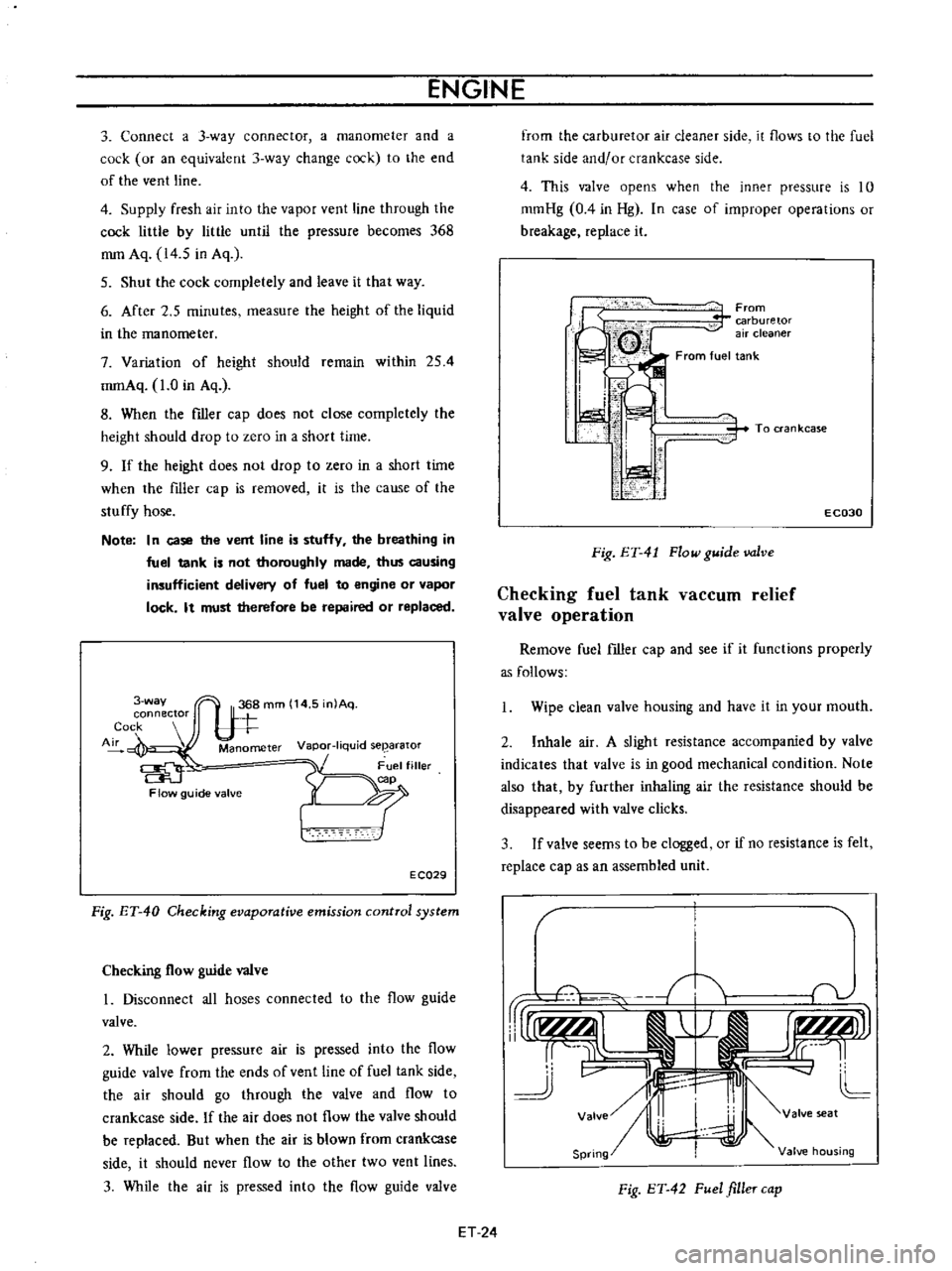
3
Connect
a
3
way
connector
a
manometer
and
a
cock
or
an
equivalent
3
way
change
cock
to
the
end
of
the
vent
line
4
Supply
fresh
air
into
the
vapor
vent
line
through
the
cock
little
by
little
until
the
pressure
becomes
368
mm
Aq
14
5
in
Aq
5
Shut
the
cock
completely
and
leave
it
that
way
6
After
2
5
minutes
measure
the
height
of
the
liquid
in
the
manometer
7
Variation
of
height
should
remain
within
254
mmAq
1
0
in
Aq
8
When
the
filler
cap
does
not
close
completely
the
height
should
drop
to
zero
in
a
short
time
9
If
the
height
does
not
drop
to
zero
in
a
short
time
when
the
filler
cap
is
removed
it
is
the
cause
of
the
stuffy
hose
Note
In
case
the
vent
line
is
stuffy
the
breathing
in
fuel
tank
is
not
thoroughly
made
thus
causing
insufficient
delivery
of
fuel
to
engine
or
vapor
lock
It
must
therefore
be
repaired
or
replaced
3
way
connector
Cock
Air
Manometer
Vapor
liquid
seearator
Flow
guide
valve
E
CQ29
Fig
ET
40
Checking
evaporative
emission
control
system
Checking
flow
guide
valve
I
Disconnect
all
hoses
connected
to
the
flow
guide
valve
2
While
lower
pressure
air
is
pressed
into
the
flow
guide
valve
from
the
ends
of
vent
line
of
fuel
tank
side
the
air
should
go
through
the
valve
and
flow
to
crankcase
side
If
the
air
does
not
flow
the
valve
should
be
replaced
But
when
the
air
is
blown
from
crankcase
side
it
should
never
flow
to
the
other
two
vent
lines
3
While
the
air
is
pressed
into
the
flow
guide
valve
from
the
carburetor
air
cleaner
side
it
flows
to
the
fuel
tank
side
and
or
crankcase
side
4
This
valve
opens
when
the
inner
pressure
is
10
mmHg
0
4
in
Hg
In
case
of
improper
operations
or
breakage
replace
it
From
carburetor
air
cleaner
From
fuel
tank
i
I
I
ti
i
i
1
1
i
To
ran
kcase
E
C030
Fig
ET
41
Flow
guide
valve
Checking
fuel
tank
vaCCUID
relief
valve
operation
Remove
fuel
filler
cap
and
see
if
it
functions
properly
as
follows
Wipe
clean
valve
housing
and
have
it
in
your
mouth
2
Inhale
air
A
slight
resistance
accompanied
by
valve
indicates
that
valve
is
in
good
mechanical
condition
Note
also
that
by
further
inhaling
air
the
resistance
should
be
disappeared
with
valve
clicks
3
If
valve
seems
to
be
clogged
or
if
no
resistance
is
felt
replace
cap
as
an
assembled
unit
T
1i
v
rUr1f
AlI
j
r
I
r
tLMJJl
rr
L
cc
11
J
v
II
4J
L
Valve
I
valve
seat
Spring
Valve
housing
Fig
ET
42
Fuel
filler
cap
ET
24
Page 378 of 513
ENGINE
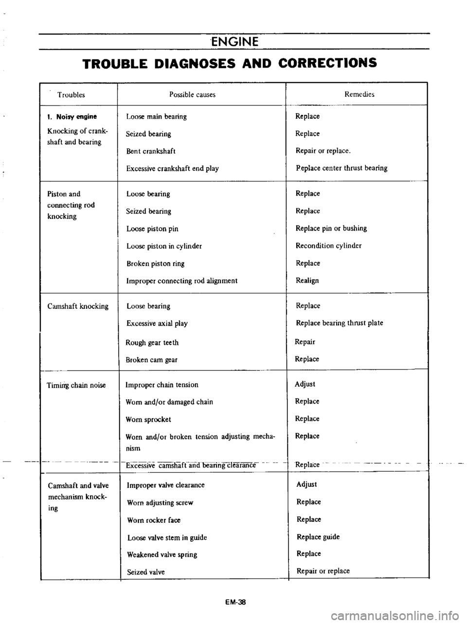
TROUBLE
DIAGNOSES
AND
CORRECTIONS
Troubles
I
Noisy
engine
Knocking
of
crank
shaft
and
bearing
Piston
and
connecting
rod
knocking
Camshaft
knocking
Timirrg
chain
noise
Camshaft
and
valve
mechanism
knock
ing
Possible
causes
Loose
main
bearing
Seized
bearing
Bent
crankshaft
Excessive
crankshaft
end
play
Loose
bearing
Seized
bearing
Loose
piston
pin
Loose
piston
in
cylinder
Broken
piston
ring
Improper
connecting
rod
alignment
Loose
bearing
Excessive
axial
play
Rough
gear
teeth
Broken
eam
gear
Improper
chain
tension
Worn
and
or
damaged
chain
Worn
sprocket
Worn
and
or
broken
tension
adjusting
mecha
nism
Excessive
camsh
ifCano
bearing
cIearance
Improper
valve
clearance
Worn
adjusting
screw
Worn
rocker
face
Loose
valve
stem
in
guide
Weakened
valve
spring
Seized
valve
EM
38
Remedies
Replace
Replace
Repair
or
replace
Peplace
center
thrust
bearing
Replace
Replace
Replace
pin
or
bushing
Recondition
cylinder
Replace
Realign
Replace
Replace
bearing
thrust
plate
Repair
Replace
Adjust
Replace
Replace
Replace
Replace
Adjust
Replace
Replace
Replace
guide
Replace
Repair
or
replace
Page 397 of 513

ENGINE
FUEL
PUMP
TESTING
A
fuel
pump
is
operating
properly
when
its
pressure
is
within
specifications
and
its
capacity
is
equal
to
the
engine
5
requirements
at
all
speeds
Pressure
and
cap
lcity
must
be
determined
by
two
tests
with
the
pump
mounted
on
the
engine
Be
sure
that
there
is
gasoline
in
the
tank
when
conducting
these
tests
Fig
EF
11
Schematic
view
of
fuel
pump
Static
pressure
test
The
static
pressure
test
is
conducted
as
follows
Disconnect
the
carburetor
fuel
line
at
the
carburetor
2
Install
the
necessary
adapter
and
tee
fitting
to
the
fuel
line
and
attach
a
suitable
pressure
gauge
Start
and
run
engine
at
varying
speeds
4
The
reading
on
the
gauge
is
the
static
fuel
pressure
and
this
should
remain
within
the
following
limits
0
18
kgJcm2
2
61b
sq
in
Pressure
below
the
lower
limit
indicates
extreme
wear
on
one
part
or
a
small
amount
of
wear
on
each
working
part
They
also
indicate
a
ruptured
diaphragm
worn
warped
dirty
or
gumming
valves
and
seats
or
weak
diaphragm
return
spring
Pressure
above
the
upper
limit
indicates
an
excessively
strong
diaphragm
that
is
too
tight
This
condition
requires
removal
of
the
fuel
pump
as
sembly
for
replacement
or
repair
Capacity
test
The
capacity
test
is
used
only
when
the
static
pressure
is
within
specifications
The
capacity
test
is
conducted
as
follows
1
Disconnect
the
fuel
pipe
at
the
carburetor
2
Place
a
suitable
container
at
the
end
of
the
pipe
3
Start
the
engine
and
run
at
1
000
rpm
4
The
pump
should
deliver
450
cc
I
V
S
p
of
fuel
in
one
minute
or
less
EF
6
Page 403 of 513
ENGINE
Step
system
The
construction
of
this
system
corresponds
to
the
idling
and
slow
system
of
the
primary
system
This
system
aims
at
the
power
filling
up
of
the
gap
when
fuel
supply
is
transferred
from
the
primary
system
to
the
secondary
system
The
step
port
is
located
near
the
auxiliary
valve
in
its
fully
closed
state
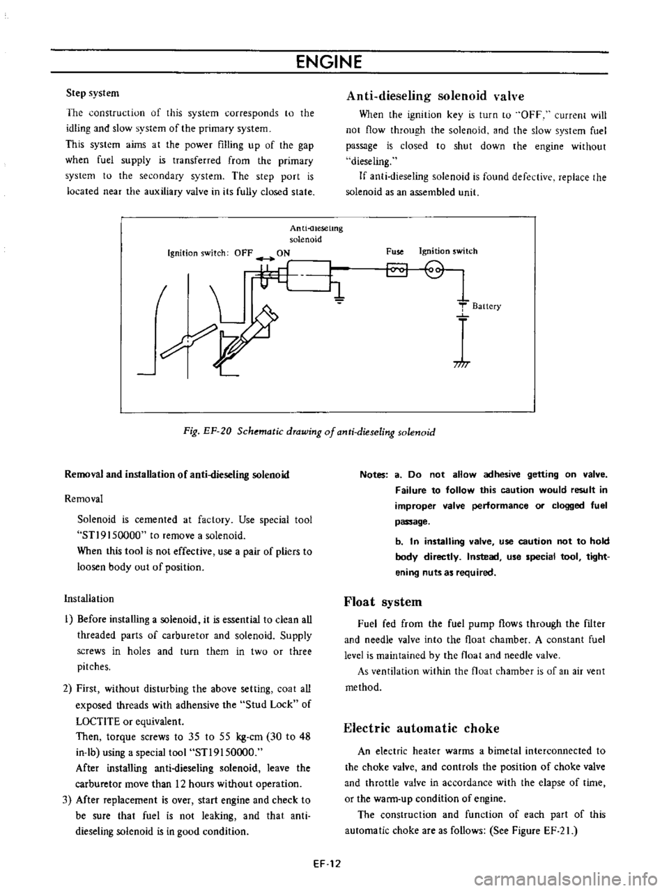
Anti
uesetmg
solenoid
Ignition
switch
OFF
ON
I
L
i1
7
I
Anti
dieseling
solenoid
valve
When
the
ignition
key
is
turn
to
OFF
current
will
not
flow
through
the
solenoid
and
the
slow
system
fuel
passage
is
closed
to
shut
down
the
engine
without
dieseling
If
anti
dieseling
solenoid
is
found
defective
replace
the
solenoid
as
an
assembled
llnit
Fuse
Ignition
switch
T
Baitery
717
Fig
EF
20
Schematic
drawing
of
anti
dieseling
solenoid
Removal
and
installation
of
anti
dieseling
solenoid
Removal
Solenoid
is
cemented
at
factory
Use
special
tool
STl9
I
50000
to
remove
a
solenoid
When
this
tool
is
not
effective
use
a
pair
of
pliers
to
loosen
body
out
of
position
Installation
I
Before
installing
a
solenoid
it
is
essential
to
clean
all
threaded
parts
of
carburetor
and
solenoid
Supply
screws
in
holes
and
turn
them
in
two
or
three
pitches
2
First
without
disturbing
the
above
setting
coat
all
exposed
threads
with
adhensive
the
Stud
Lock
of
LOCTlTE
or
equivalent
Then
torque
screws
to
35
to
55
kg
cm
30
to
48
in
lb
using
a
special
tool
STl9150000
After
installing
anti
dieseling
solenoid
leave
the
carburetor
move
than
12
hours
without
operation
3
Mter
replacement
is
over
start
engine
and
check
to
be
sure
that
fuel
is
not
leaking
and
that
anti
dieseling
solenoid
is
in
good
condition
Notes
a
Do
not
allow
adhesive
getting
on
valve
Failure
to
follow
this
caution
would
result
in
improper
valve
performance
or
clogged
fuel
passage
b
In
installing
valve
use
caution
not
to
hold
body
directly
Instead
use
special
tool
tight
ening
nuts
as
required
Float
system
Fuel
fed
from
the
fuel
pump
flows
through
the
filter
and
needle
valve
into
the
float
chamber
A
constant
fuel
level
is
maintained
by
the
float
and
needle
valve
As
ventilation
within
the
float
chamber
is
of
an
air
vent
method
Electric
automatic
choke
An
electric
heater
warms
a
bimetal
interconnected
to
the
choke
valve
and
controls
the
position
of
choke
valve
and
throttle
valve
in
accordance
with
the
elapse
of
time
or
the
warm
up
condition
of
engine
The
construction
and
function
of
each
part
of
this
automatic
choke
are
as
follows
See
Figure
EF
21
EF
12
Page 404 of 513
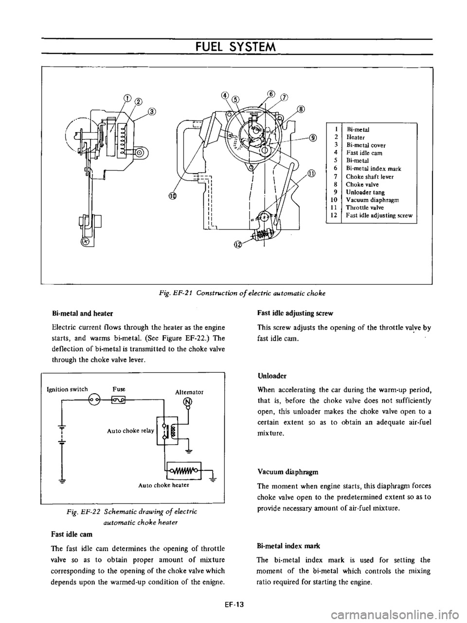
FUEl
SYSTEM
l
I
@
1J
w
I
I
I
I
1
1
1
t
2
3
4
5
6
7
8
9
10
tt
12
Hi
metal
Heater
Bi
metal
cover
Fast
idle
earn
Bi
metal
Bi
metal
index
mark
Choke
shaft
lever
Choke
valve
Unloader
tang
Vacuum
diaphragm
Throttle
valve
Fast
idle
adjusting
screw
j
@
Fig
EP
21
Construction
of
electric
automatic
choke
Bi
metal
and
heater
Electric
current
flows
through
the
heater
as
the
engine
starts
and
warms
bi
metal
See
Figure
EF
22
The
deflection
of
bi
metal
is
transmitted
to
the
choke
valve
through
the
choke
valve
lever
Ignition
switch
Fuse
Alternator
T
o
o
Auto
choke
relay
Auto
choke
heater
Fig
EF
22
Schematic
drawing
of
electric
automatic
choke
heater
Fast
idle
C3m
The
fast
idle
cam
determines
the
opening
of
throttle
valve
so
as
to
obtain
proper
amount
of
mixture
corresponding
to
the
opening
of
the
choke
valve
which
depends
upon
the
warmed
up
condition
of
the
enigne
Fast
idle
adjusting
screw
This
screw
adjusts
the
opening
of
the
throttle
valve
by
fast
idle
cam
Unloader
When
accelerating
the
car
during
the
warm
up
period
that
is
before
the
choke
valve
does
not
sufficiently
open
this
unloader
makes
the
choke
valve
open
to
a
certain
extent
so
as
to
obtain
an
adequate
air
fuel
mixture
Vacuum
diaphragm
The
moment
when
engine
starts
this
diaphragm
forces
choke
valve
open
to
the
predetermined
extent
so
as
to
provide
necessary
amount
of
air
fuel
mixture
Bi
metaI
index
mark
The
bi
metal
index
mark
is
used
for
setting
the
moment
of
the
bi
metal
which
controls
the
mixing
ratio
required
for
starting
the
engine
EF
13
Page 411 of 513
ENGINE
Y
Q
0
Fig
EF
34
Disassembling
accelerator
pump
and
hi
metal
cover
1
EC013
Fig
EF
35
Removing
throttle
chamber
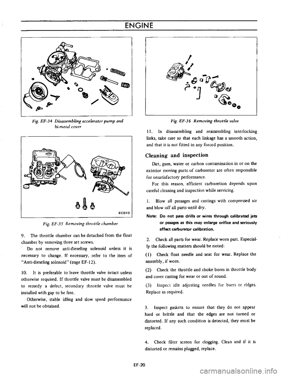
9
The
throttle
chamber
can
be
detached
from
the
float
chamber
by
removing
three
set
screws
Do
not
remove
anti
dieseling
solenoid
unless
it
is
necessary
to
change
If
necessary
refer
to
the
item
of
Anti
dieseling
solenoid
page
EF
12
10
It
is
preferable
to
leave
throttle
valve
intact
unless
otherwise
required
If
throttle
valve
must
be
disassembled
to
remedy
a
defect
secondary
throttle
valve
must
be
installed
with
gap
to
be
free
Otherwise
stable
idling
and
slow
speed
performance
will
not
be
obtained
I
o
rJ
01
o
o
Fig
EF
36
Removing
throttle
valve
II
In
disassembling
and
reassembling
interlocking
links
take
care
so
that
each
linkage
has
a
smooth
action
and
that
it
is
not
fitted
in
any
forced
position
Cleaning
and
inspection
Dirt
gum
water
or
carbon
contamination
in
or
on
the
exterior
moving
parts
of
carburetor
are
often
responsible
for
unsatisfactory
performance
For
this
reason
efficient
carburetion
depends
upon
careful
cleaning
and
inspection
while
servicing
1
Blow
aU
passages
and
castings
with
compressed
air
and
blow
off
all
parts
until
dry
Note
Do
not
pass
drills
or
wires
through
calibrated
jets
or
pssages
as
this
may
enlarge
orifice
and
seriously
affect
carburetor
calibration
2
Check
all
parts
for
wear
Replace
worn
part
Especial
ly
the
following
matters
should
be
noted
I
Check
float
needle
and
seat
for
wear
Replace
the
assembly
if
worn
2
Check
the
throttle
and
choke
bores
in
throttle
body
and
cover
casting
for
wear
or
out
of
round
3
Inspect
idle
adjusting
needles
fur
burrs
or
ridges
Replace
as
required
3
Inspect
gaskets
to
ensure
that
they
do
not
appear
hard
or
brittle
and
that
the
edges
are
not
turned
or
distorted
If
any
such
condition
is
detected
they
must
be
replaced
4
Check
fIlter
screen
for
clogging
Clean
and
if
it
is
distorted
or
remains
plugged
replace
EF
20
Page 412 of 513
FUEL
SYSTEM
5
Check
venturi
clusters
for
loose
or
worn
parts
If
damage
or
looseness
exists
replace
cluster
assembly
6
Check
the
linkage
for
operating
condition
7
Inspect
the
operation
of
accelerating
pump
Pour
gasoline
into
the
float
chamber
and
operate
the
throttle
lever
Check
condition
of
gasoline
injection
from
the
accelerating
nozzle
Assembly
and
instalIetion
Assemble
and
install
the
carburetor
in
reverse
sequence
of
disassembly
and
removal
Replace
the
gaskets
if
necessary
When
disassembling
and
reassembling
the
interlock
link
and
related
components
be
careful
not
to
bend
or
deform
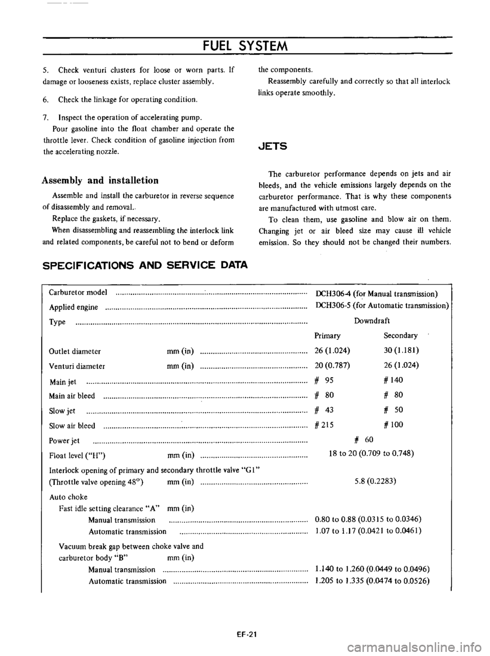
SPECIFICATIONS
AND
SERVICE
DATA
Carburetor
model
Applied
engine
Type
Outlet
diameter
mm
in
rom
in
Venturi
diameter
Main
jet
Main
air
bleed
Slow
jet
Slow
air
bleed
Power
jet
Float
level
H
rom
in
Interlock
opening
of
primary
and
secondary
throttle
valve
G
I
Throttle
valve
opening
480
mm
in
Auto
choke
Fast
idle
setting
clearance
A
mm
in
Manual
transmission
Automatic
transmission
Vacuum
break
gap
between
choke
valve
and
carburetor
body
8
mm
in
Manual
transmission
Automatic
transmission
EF
21
the
components
Reassembly
carefully
and
correctly
so
that
all
interlock
links
operate
smoothly
JETS
The
carburetor
performance
depends
on
jets
and
air
bleeds
and
the
vehicle
emissions
largely
depends
on
the
carburetor
performance
That
is
why
these
components
are
manufactured
with
utmost
care
To
clean
them
use
gasoline
and
blow
air
on
them
Changing
jet
or
air
bleed
size
may
cause
ill
vehicle
emission
So
they
should
not
be
changed
their
numbers
DCH3064
for
Manual
transmission
DCH306
5
for
Automatic
transmission
Downdraft
Primary
Secondary
26
1
024
30
1
181
20
0
787
26
1
024
1
95
1
140
1
80
1
80
1
43
1
50
1
215
1
100
1
60
18
to
20
0
709
to
0
748
5
8
0
2283
0
80
to
0
88
0
0315
to
0
0346
1
07
to
1
17
0
0421
to
0
0461
1
140
to
1
260
0
0449
to
0
0496
1
205
to
1
335
0
0474
to
0
0526
Page 418 of 513
FUEL
SYSTEM
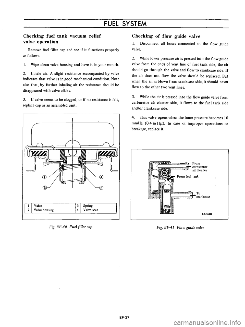
Checking
fuel
tank
vacuum
relief
valve
operation
Remove
fuel
filler
cap
and
see
if
it
functions
properly
as
follows
Wipe
clean
valve
housing
and
have
it
in
your
mouth
2
Inhale
air
A
slight
resistance
accompanied
by
valve
indicates
that
valve
is
in
good
mechanical
condition
Note
also
that
by
further
inhaling
air
the
resistance
should
be
disappeared
with
valve
clicks
3
If
valve
seems
to
be
clogged
or
if
no
resistance
is
felt
replace
cap
as
an
assembled
unit
1
1
1I
L
CD
hl
cv
CID
t
I
Valve
2
Valve
housing
I
I
Spring
Valve
seat
Fig
EF
40
Fuel
filleT
cap
EF
27
Checking
of
flow
guide
valve
1
Disconnect
all
hoses
connected
to
the
flow
guide
valve
2
While
lower
pressure
air
is
pressed
into
the
flow
guide
valve
from
the
ends
of
vent
line
of
fuel
tank
side
the
air
should
go
through
the
valve
and
flow
to
crankcase
side
If
the
air
does
not
flow
the
valve
should
be
replaced
But
when
the
air
is
blown
from
crankcase
side
it
should
never
flow
to
the
other
two
vent
lines
3
While
the
air
is
pressed
into
the
flow
guide
valve
from
carburetor
air
cleaner
side
it
flows
to
the
fuel
tank
side
and
or
crankcase
side
4
This
valve
opens
when
the
inner
pressure
becomes
10
romHg
0
4
in
Hg
In
case
of
improper
operations
or
breakage
replace
it
iFrom
r
carburetor
air
cleaner
From
fuel
tank
To
r
crankcase
j
iJ
i
ill
1
1
EC030
Fig
EF
4
J
Flow
guide
valve