1973 DATSUN B110 parking brake
[x] Cancel search: parking brakePage 58 of 513
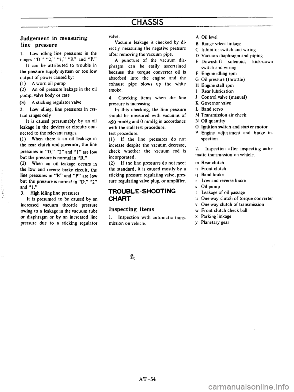
Judgement
in
measurmg
line
pressure
I
Low
idling
line
pressures
in
the
ranges
D
2
loR
and
P
It
can
be
artributed
to
trouble
in
the
pressure
supply
system
or
too
low
output
of
power
caused
by
1
A
worn
oil
pump
2
An
oil
pressure
leakage
in
the
oil
pump
valve
body
or
case
3
A
sticking
regulator
valve
2
Low
idling
line
pressures
in
cer
tain
ranges
only
It
is
caused
pressumabIy
by
an
oil
leakage
in
the
devices
or
circuits
con
nected
to
the
relevant
ranges
1
When
there
is
an
oil
leakage
in
the
rear
clutch
and
governor
the
line
pressures
in
D
2
and
I
are
low
but
the
pressure
is
normal
in
R
2
When
an
oil
leakage
occurs
in
the
low
and
reverse
brake
circuit
the
line
pressures
in
R
and
p
are
low
but
the
pressure
is
normal
in
0
2
and
I
3
High
idling
line
pressures
It
is
presumed
to
be
caused
by
an
increased
vacuum
throttle
pressure
owing
to
a
leakage
in
the
vacuum
tube
or
diaphragm
or
by
an
increased
line
pressure
due
to
a
sticking
regulator
CHASSIS
valve
Vacuum
leakage
is
checked
by
di
reetly
measuring
the
negative
pressure
after
removing
the
vacuum
pipe
A
puncture
of
the
vacuum
dia
phragm
can
be
easily
ascertained
because
the
torque
converter
oil
is
absorbed
into
the
engine
and
the
exhaust
pipe
blows
up
the
white
smoke
4
Checking
items
when
the
line
pressure
is
increasing
In
trJs
checking
the
line
pressure
should
be
measured
with
vacuums
of
450
mmHg
and
0
mmHg
in
accordance
with
the
stall
test
procedure
test
procedure
1
If
the
line
pressures
do
not
increase
despite
the
vacuum
decrease
check
whether
the
vacuum
rod
is
incorporated
2
If
the
line
pressures
do
not
meet
the
standard
it
is
caused
mostly
by
a
sticking
pressure
regulating
valve
pres
sure
regulating
valve
plug
or
amptifier
TROUBLE
SHOOTING
CHART
Inspecting
items
1
Inspection
with
automatic
trans
mission
on
vehicle
J
AT
54
A
Oil
level
B
Range
selecr
linkage
C
Inhibitor
switch
and
wiring
D
Vacuum
diaphragm
and
piping
E
Downshift
solenoid
kick
down
switch
and
wiring
F
Engine
idling
rpm
G
Oil
pressure
throttle
H
Engine
stall
rpm
I
Rear
lubrication
J
Control
valve
manual
K
Governor
valve
L
Band
servo
M
Transmission
air
check
N
Oil
quantity
o
Ignition
switch
and
starter
motor
P
Engine
adjustment
and
brake
in
spection
2
Inspection
after
inspecting
auto
matic
transmission
on
vehicle
m
Rear
clutch
n
Front
clutch
q
Band
brake
r
Low
and
reverse
brake
s
Oil
pump
Leakage
of
oil
passage
u
One
way
clutch
of
torque
converter
v
One
way
clutch
of
transmission
w
Front
clutch
check
ball
x
Parking
linkage
y
Planetary
gear
Page 61 of 513
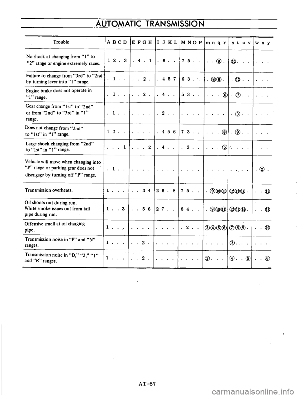
AUTOMATIC
TRANSMISSIO
N
Trouble
IA
BCD
IE
F
G
H
IIJ
K
L
1M
NO
P
1m
n
q
riB
t
u
v
w
x
y
No
shock
at
changing
from
I
to
7
5
@
@
I
1
2
3
4
1
6
I
2
range
or
engine
extremely
races
Failure
to
change
from
3rd
to
2nd
1
2
4
5
7
16
3
I
@@
@
by
turning
lever
into
I
range
Engine
brake
does
not
operate
in
I
2
4
5
3
@
J
I
range
Gear
change
from
1st
to
2nd
or
from
2nd
to
3rd
in
I
I
2
@
range
Does
not
change
from
2nd
1
2
456
7
3
@
@
to
1st
in
I
range
Large
shock
changing
from
2nd
1
2
4
3
IDI
to
1st
in
I
range
Vehicle
will
move
when
changing
into
P
range
or
parking
gear
does
not
1
@
disengage
by
turning
off
P
range
Transmission
overheats
1
3
4
12
6
8
7
5
@@@I@@
@
Oil
shoots
out
during
run
@@@
@@
@
White
smoke
issues
out
from
tail
1
3
5
6
2
7
8
4
pipe
during
run
Offensive
smell
at
oil
charging
11
2
I@
@
ID@I
J
@@
@
pipe
Transmission
noise
in
P
and
N
1
2
I
I@
ranges
Transmission
noise
in
0
2
I
1
2
@
@
@
@
and
R
ranges
AT
57
Page 66 of 513
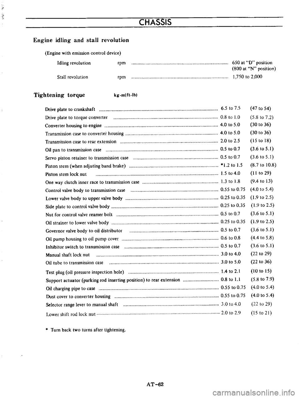
CHASSIS
Engine
idling
and
stall
revolution
Engine
with
emission
control
device
Idling
revolution
rpm
650
at
0
position
800
at
N
position
1
750
to
2
000
Stall
revolution
rpm
Tightening
torque
kg
m
ft
Ib
Test
plug
oil
pressure
inspection
hole
Support
actuator
parking
rod
inserting
position
to
rear
extension
Oil
charging
pipe
to
case
Dust
cover
to
converter
housing
Selector
range
lever
to
manual
shaft
Lower
shift
rod
lock
nut
6
5
t07
5
47
to
54
0
8
to
1
0
5
8
to
7
2
4
0
to
5
0
30
to
36
4
0
to
5
0
30
to
36
2
0
to
2
5
15
to
18
0
5
to
0
7
3
6
to
5
1
0
5
to
0
7
3
6toS
I
1
2
to
1
5
8
7
to
10
8
1
5
to
4
0
II
to
29
1
3
to
1
8
9
4
to
13
0
55
to
0
75
4
0
to
5
4
0
25
to
0
35
1
9
to
2
5
0
25
to
0
35
1
9
to
2
5
0
5
to
0
7
3
6
to
5
I
0
25
to
0
35
1
9
to
2
5
0
5
to
0
7
3
6
to
5
1
0
6
to
0
8
4
4
to
5
8
0
5
to
0
7
3
6
to
5
1
3
0
to
4
0
22
to
29
3
0
to
5
0
22
to
36
14
to
2
1
10
to
15
0
8
to
l
l
5
8
to
7
9
0
55
to
0
75
4
0
to
5
4
0
55
to
0
75
4
0
to
5
4
3
0
to
4
0
22
to
29
2
0
to
2
9
15
to
21
Drive
plate
to
crankshaft
Drive
plate
to
torque
converter
Converter
housing
to
engine
Transmission
case
to
converter
housing
Transmission
case
to
rear
extension
Oil
pan
to
transmission
case
Servo
piston
retainer
to
transmission
case
Piston
stem
when
adjuting
band
brake
Piston
stem
lock
nut
One
way
clutch
inner
race
to
transmission
case
Control
valve
body
to
transmission
case
Lower
valve
body
to
upper
valve
body
Side
plate
to
control
valve
body
Nut
for
control
valve
reamer
bolt
Oil
strainer
to
lower
valve
body
Governor
valve
body
to
oil
distributor
Oil
pump
housing
to
oil
pump
cover
Inhibitor
switch
to
transmh
sion
case
Manual
shaft
lock
nut
Oil
tube
to
transmission
case
Turn
back
two
turns
after
tightening
AT
62
Page 157 of 513

CHASSIS
Tire
rotation
Tires
wear
unevenly
and
become
unbalanced
according
to
running
distance
Uneven
tire
wear
often
results
in
tire
noise
whkh
is
attributed
to
rear
axle
gears
bearing
ell
Meanwhile
the
front
tires
tend
to
wear
unevenly
because
of
front
wheel
alignment
Accordingly
to
equalize
tire
wear
it
is
necessary
to
rotate
tires
every
10
000
km
6
000
miles
of
operation
RIGHT
FRONT
RIGHT
REAR
r
1
Xl
L
J
LEFT
FRONT
LEFT
REAR
Fig
WT
2
Tire
rotation
The
tires
are
provided
with
tread
wear
indicator
at
six
places
around
tire
circumference
indicating
1
6
nun
0
16
in
tread
depth
When
the
tires
wear
and
then
the
marks
a
ppear
replace
them
with
new
ones
TREAD
WEAR
INDICATOR
7
TREAD
m
Y
X
W
X
v
w
WH024
Fig
WI
3
Tread
wear
illdicator
To
change
tire
with
wheel
using
a
jack
in
the
safe
manner
observe
the
following
procedures
I
Apply
parking
brake
and
block
front
wheels
when
rear
wheel
is
being
changed
2
Remove
wheel
cap
and
loosen
wheel
nuts
3
Place
jack
at
jacking
point
instructed
under
General
Information
and
raise
car
until
wheel
clears
ground
4
Remove
wheel
nuts
and
whed
from
drum
5
To
install
wheel
reverse
the
above
steps
Tighten
whed
nuts
in
criss
cross
fashion
to
8
0
to
9
0
kg
m
58
to
65
ft
lb
Note
Never
get
under
the
car
while
it
is
supported
only
by
the
jack
Always
use
safety
stands
to
support
the
side
member
of
body
construction
when
you
must
get
beneath
the
car
INSPECTION
Wheel
balance
The
wheel
and
tire
assembly
should
be
kept
balanced
statically
and
dynamically
Proper
tire
balance
is
necessary
when
driving
the
car
at
high
speeds
Consequently
the
wheel
and
tire
assembly
should
be
properly
rebalanced
whenever
puncture
is
repaired
The
wheel
and
tire
assembly
becomes
out
of
balance
according
to
uneven
tire
wear
Severe
acceleration
and
braking
or
fast
cornering
is
the
cause
of
wear
on
tire
resulting
in
unbalance
of
tire
and
wheel
assembly
The
symptom
of
unbalance
appears
as
tramp
car
shake
and
steering
trouble
To
correct
unbalance
use
proper
wheel
balancer
Maximum
allowable
unbalance
165
gr
cm
2
3
in
ol
at
rim
circumferences
Balance
weight
10
to
70
gr
0
35
to
2
47
Ol
at
10
gr
0
35
Ol
interval
Note
Be
sure
to
place
the
correct
balance
weights
on
the
inner
edge
of
rim
as
shown
in
Figure
WT
4
Wheel
and
tire
In
order
to
ensure
satisfactory
steering
condition
as
well
as
maximum
tire
life
proceed
as
follows
I
Check
wheel
rim
especially
rim
flange
and
bead
seat
for
rust
distortion
cracks
or
other
defects
which
might
cause
air
leaks
Function
of
tubeless
tire
depends
on
a
good
seal
between
tire
bead
and
wheel
rim
Thoroughly
remove
rust
dust
oxidized
rubber
or
sand
from
wheel
rim
with
wire
brush
emery
cloth
or
paper
Use
dial
gauge
to
examine
wheel
rim
for
lateral
and
diametral
run
out
WT
4
Page 245 of 513
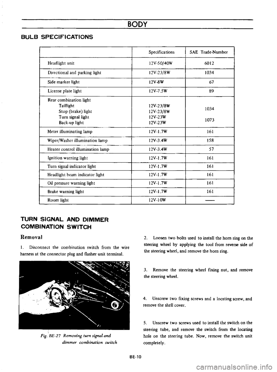
BULB
SPECIFICATIONS
Headlight
unit
Directional
and
parking
light
Side
marker
light
License
plate
light
Rear
combination
light
Taillight
Stop
brake
light
Turn
signal
light
Back
up
light
Meter
illuminating
lamp
Wiper
Washer
illumination
lamp
Heater
control
illumination
lamp
Ignition
warning
light
Turn
signal
indicator
light
Headlight
beam
indicator
light
Oil
pressure
warning
light
Brake
warning
ligh
t
Room
light
TURN
SIGNAL
AND
DIMMER
COMBINATION
SWITCH
Removal
Disconnect
the
combination
switch
from
the
wire
harness
at
the
connector
plug
and
flasher
unit
terrninal
Fig
BE
27
Removing
turn
signal
and
dimmer
combination
switch
BODY
Specifications
SAE
Trade
Number
12V
SO
40W
6012
12V
23
8W
1034
12V
8W
67
l2V
7
5W
89
12V
23
8W
1034
l2V
23
8W
l2V
23W
1073
l2V
23W
12V
I
7W
161
l2V
3
4W
158
l2V
3
4W
57
l2V
17W
161
l2V
17W
161
l2V
17W
161
l2V
17W
161
l2V
17W
161
l2V
IOW
2
Loosen
two
bolts
used
to
install
the
horn
ring
on
the
steering
wheel
by
applying
the
tool
from
reverse
side
of
the
steering
wheel
and
remove
the
horn
ring
3
Remove
the
steering
wheel
fixing
nut
and
remove
the
steering
wheel
4
Unscrew
two
fixing
screws
and
a
locating
screw
and
remove
the
shell
cover
5
Unscrew
two
screws
used
to
install
the
switch
on
the
steering
tube
and
remove
the
switch
from
the
locating
hole
on
the
steering
tube
Now
remove
the
switch
unit
completely
BE
10
Page 313 of 513
ENGINE
Adjusting
carburetor
idle
rpm
mixture
ratio
Idle
mixture
adjustment
requires
the
use
of
a
CO
meter
When
preparing
to
adjust
idle
mixture
it
is
essential
to
have
the
meter
thoroughly
warmed
and
calibrated
Warm
up
the
engine
sufficiently
2
Continue
engine
operation
for
one
minute
under
idling
speed
3
Adjust
throttle
adjusting
screw
so
that
engine
speed
is
800
rpm
in
NO
position
for
automatic
transmission
4
Check
ignition
timing
if
necessary
adjust
it
to
the
specifications
Ignition
timing
SO
800
rpm
S
Adjust
idle
adjusting
screw
so
that
CO
percentage
is
1
5
t
O
S
6
Repeat
the
adjustments
as
described
in
steps
3
and
S
above
so
that
CO
percentage
is
I
i
t
O
S
at
800
rpm
Cautions
a
On
automatic
transmission
equipped
model
check
must
be
done
in
the
0
position
Be
sure
to
apply
parking
brake
and
to
lock
both
front
and
rear
wheels
with
wheel
chocks
b
Hold
brake
pedal
while
stepping
down
on
accelerator
pedal
Otherwise
car
will
rush
out
dangerously
7
On
automatic
transmission
equipped
model
make
sure
that
the
adjustment
has
been
made
with
the
selector
lever
in
N
position
And
then
check
the
specifications
with
the
lever
in
D
position
Insure
that
CO
percent
and
idle
speed
are
as
follows
Idle
rpm
CO
percentage
with
lever
in
D
position
6S0
I
S
t
O
S
If
necessary
adjust
by
progressively
turning
throttle
adjusting
screw
and
idle
adjusting
screw
until
correct
adjustments
are
made
Notes
a
Do
not
attempt
to
screw
down
the
idle
adjusting
screw
completely
to
avoid
damage
to
the
tip
which
will
tend
to
cause
malfunctions
b
After
idle
adjustment
has
been
made
shift
the
lever
to
N
or
p
position
for
automatic
transmission
c
Remove
wheel
chocks
before
starting
the
car
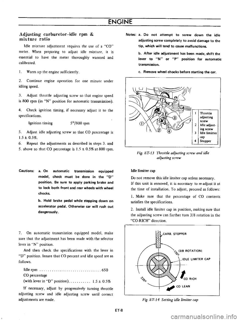
Throttle
adjusting
screw
Idle
adjust
ing
screw
3
Idle
limitter
cap
4
Stopper
Fig
ET
13
Throttle
adjusting
screw
and
idle
adjusting
screw
Idle
limiter
cap
Do
not
remove
this
idle
limiter
cap
unless
necessary
If
this
unit
is
removed
it
is
necessary
to
re
adjust
it
at
the
time
of
installation
To
adjust
proceed
as
follows
L
Make
sure
that
the
percentage
of
CO
contents
satisfies
the
specifications
2
Install
idle
limiter
cap
in
position
making
sure
that
the
adjusting
screw
can
further
turn
3
8
rotation
in
the
CO
RICH
direction
CARB
STOPPER
J
Z
3
8
ROTATION
0
IDLE
LIMITER
CAP
0
to
RICH
CO
LEAN
Fig
l
T
14
Setting
idle
limiter
cap
ET
8
Page 325 of 513
ENGINE
Caution
lock
the
front
and
rear
wheels
by
fully
pulling
the
parking
brake
lever
before
con
ducting
this
test
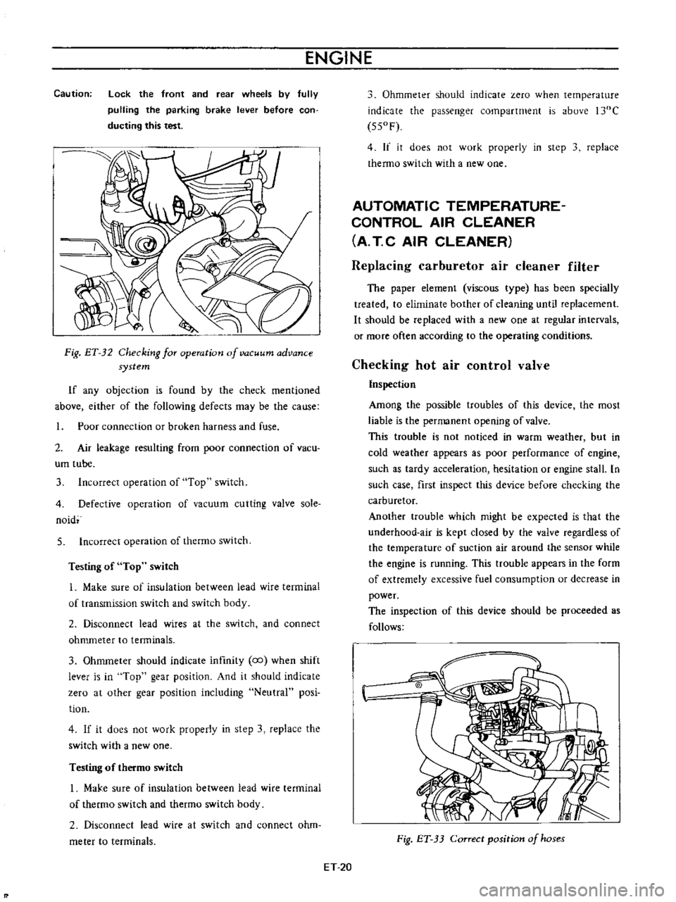
Fig
ET
32
Checking
for
operation
of
vacuum
advance
system
If
any
objection
is
found
by
the
check
mentioned
above
either
of
the
following
defects
may
be
the
cause
Poor
connection
or
broken
harness
and
fuse
2
Air
leakage
resulting
from
poor
connection
of
vacu
um
tube
3
Incorrect
operation
of
Top
switch
4
Defective
operation
of
vacuum
cutting
valve
sole
naid
5
Incorrect
operation
of
thermo
switch
Testing
of
Top
switch
1
Make
sure
of
insulation
between
lead
wire
terminal
of
transmission
switch
and
switch
body
2
Disconnect
lead
wires
at
the
switch
and
connect
ohmmeter
to
tenninals
3
Ohmmeter
should
indicate
infmity
co
when
shift
lever
is
in
Top
gear
position
And
it
should
indicate
zero
at
other
gear
position
including
Neutral
posi
tion
4
If
it
does
not
work
properly
in
step
3
replace
the
switch
with
a
new
one
Testing
of
thermo
switch
I
MaJ
e
sure
of
insulation
between
lead
wire
terminal
of
thermo
switch
and
thetmo
switch
body
2
Disconnect
lead
wire
at
switch
and
connect
ohm
meter
to
terminals
Ohmmeter
should
indicate
zero
when
temperature
indicate
the
passenger
compartment
is
above
l30C
550F
4
If
it
does
not
work
properly
in
step
3
replace
thermo
switch
with
a
new
one
AUTOMATIC
TEMPERATURE
CONTROL
AIR
CLEANER
A
T
C
AIR
CLEANER
Replacing
carburetor
air
cleaner
filter
The
paper
element
viscous
type
has
been
specially
treated
to
eliminate
bother
of
cleaning
until
replacement
It
should
be
replaced
with
a
new
one
at
regular
intervals
or
more
often
according
to
the
operating
conditions
Checking
hot
air
control
valve
Inspection
Among
the
possible
troubles
of
this
device
the
most
liable
is
the
permanent
opening
of
valve
This
trouble
is
not
noticed
in
warm
weather
but
in
cold
weather
appears
as
poor
performance
of
engine
such
as
tardy
acceleration
hesitation
or
engine
stall
In
such
case
first
inspect
this
device
before
checking
the
carburetor
Another
trouble
which
might
be
expected
is
that
the
underhood
air
is
kept
closed
by
the
valve
regardless
of
the
temperature
of
suction
air
around
the
sensor
while
the
engine
is
running
This
ttOuble
appears
in
the
form
of
extremely
excessive
fuel
consumption
or
decrease
in
power
The
inspection
of
this
device
should
be
proceeded
as
follows
Fig
ET
33
Correct
position
of
hoses
ET
20
Page 405 of 513
ENGINE
AD
JUSTMENT
Idling
adjustment
Idle
mixture
adjustment
requires
the
use
of
a
CO
meter
When
preparing
to
adjust
idle
mixture
it
is
essential
to
have
the
meter
thoroughly
warmed
and
calibrated
Warm
up
the
engine
sufficiently
2
Continue
engine
operation
for
one
minute
under
idling
speed
3
Adjust
throttle
adjusting
screw
so
that
engine
speed
is
800
rpm
in
N
position
for
automatic
transmission
4
Check
ignition
timing
if
necessary
adjust
it
to
the
specifications
Ignition
timing
50
800
rpm
5
Adjust
idle
adjusting
screw
so
that
ca
percentage
is
1
5
t
0
5
6
Repeat
the
adjustments
as
described
in
steps
3
and
5
above
so
that
ca
percentage
is
1
5
to
5
at
800
rpm
Cautions
a
On
automatic
transmission
equipped
model
check
must
be
done
in
the
0
position
Be
sure
to
apply
parking
brake
and
to
lock
both
front
and
rear
wheels
with
wheel
chocks
b
Hold
brake
pedal
while
stepping
down
on
accelerator
pedal
Otherwise
car
will
rush
out
dangerously
7
On
automatic
transmission
equipped
model
make
sure
that
the
adjustment
has
been
made
with
the
selector
lever
in
N
position
And
then
check
the
specifications
with
the
lever
in
D
position
Insure
that
CO
percent
and
idle
speed
are
as
follows
Idle
rpm
650
ca
percentage
with
lever
in
D
position
15
to
5
If
necessary
adjust
by
progressively
turning
throttle
adjusting
screw
and
idle
adjusting
screw
until
correct
adjustments
are
made
Notes
a
Do
not
attempt
to
screw
down
the
id
Ie
adjusting
screw
completely
to
avoid
damage
to
the
EF
14
tip
which
will
tend
to
cause
malfunctions
b
After
idle
adjustment
has
been
made
shift
the
lever
to
N
or
p
position
for
automatic
transmission
c
Remove
wheel
chocks
before
starting
the
car
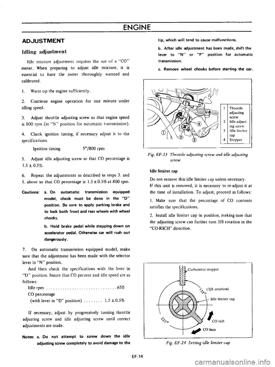
Throttle
adjusting
screw
2
Idle
adjust
ing
crew
3
Idle
limiter
cap
4
Stopp
r
Fig
EF
23
Throttle
adjusting
screw
and
idle
adjusting
screw
Idle
limiter
cap
Do
not
remove
this
idle
limiter
cap
unless
necessary
If
this
unit
is
removed
it
is
necessary
to
fe
adjust
it
at
the
time
of
installation
To
adjust
proceed
as
follows
1
Make
sure
that
the
percentage
of
CO
contents
satisfies
the
specifications
2
Install
idle
limiter
cap
in
position
making
sure
that
the
adjusting
screw
can
further
turn
3
8
rotation
in
the
Ca
RICH
direction
j
j
Carburetor
stopper
o
u
o
i
r
3
8
rotation
0
0
Idle
limiter
cap
0
0
CO
lean
Fig
EF
24
Setting
idle
limite
cap