1973 DATSUN B110 check oil
[x] Cancel search: check oilPage 365 of 513
ENGINE
MECHANICAL
Standard
mm
in
Camshaft
sprocket
run
out
Thrust
deviation
O
OIS
0
0006
Locating
plate
thrust
clearance
0
02
to
0
08
0
0008
to
0
003
Wear
limit
mm
in
less
than
0
0
0039
O
OS
0
0020
0
1
0
0039
3
Check
the
chain
for
damage
excessive
wear
and
stretch
at
its
roller
links
Replace
chain
if
defective
Flyw
heel
I
Check
the
clutch
disc
contact
surface
of
the
flywheel
for
damage
and
wear
Repair
or
replace
if
necessary
2
Measure
deviation
of
the
clutch
disc
contact
surface
with
a
dial
gauge
If
it
exceeds
0
2
mm
0
0079
in
replace
it
3
Check
tooth
surfaces
of
the
ring
gear
for
flaw
and
wear
Replace
if
necessary
Note
Replace
the
ring
gear
at
about
180
to
2000C
356
to
3920
Fl
ENGINE
ASSEMBLY
PRECAUTION
CYLINDER
HEAD
PRECAUTION
CONTENTS
EM
25
EM
25
Use
thoroughly
cleaned
parts
Particularly
make
sure
that
oil
holes
are
clear
of
foreign
matter
2
When
installing
sliding
parts
such
as
bearings
be
sure
to
apply
engine
oil
to
them
3
Use
new
packings
and
oil
seals
4
Keep
tools
and
work
benches
clean
S
Keep
the
necessary
parts
and
tools
near
at
hand
6
Be
sure
to
follow
specified
tightening
torque
and
orders
CYLINDER
HEAD
Assembly
of
valve
and
valve
spring
Set
the
valve
spring
seat
in
position
and
fit
the
valve
guide
with
the
oil
lip
seal
Assemble
the
parts
in
order
valve
spring
spring
retainer
valve
collet
and
valve
rocker
guide
PISTON
AND
CONNECTING
ROO
ASSEMBLING
ENGINE
EM
25
EM
26
I
I
11
00
I
I
I
t
I
J
ftr
J
J
1
l
J
r
N
1
n
r
VI
I
I
C
I
L
I
Fig
EM
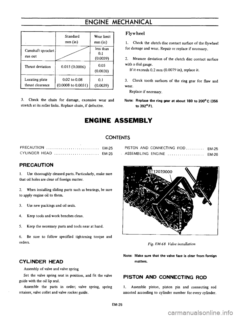
68
Valve
installation
Note
Make
sure
that
the
valve
face
is
clear
from
foreign
matters
PISTON
AND
CONNECTING
ROD
Assemble
piston
piston
pin
and
connecting
rod
assorted
according
to
cylinder
number
for
every
cylinder
EM
25
Page 367 of 513
ENGINE
MECHANICAL
3
Apply
engine
oil
to
the
main
bearing
surfaces
on
both
sides
of
the
cylinder
block
and
cap
Install
the
crankshaft
4
Install
the
main
bearing
cap
and
tighten
the
bolts
with
specified
torque
Tightening
torque
5
0
to
6
0
kg
m
36
to
43
ft
lb
Notes
a
Arrange
the
parts
so
that
the
arrow
mark
on
the
bearing
cap
is
faced
toward
the
front
of
the
engine
b
Prior
to
tightening
the
bearing
cap
bolts
place
the
bearing
cap
at
a
proper
position
by
shifting
the
crankshaft
in
the
axial
direction
c
Tighten
the
bearing
cap
bolts
gradually
in
separating
two
to
three
stages
and
outwardly
from
the
center
beari
ng
d
After
securing
the
bearing
cap
bolts
ascertain
that
the
crankshaft
can
be
easily
rotated
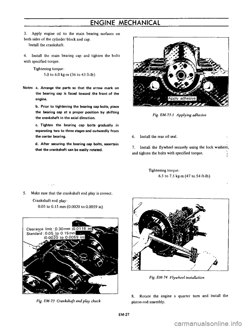
5
Make
sure
that
the
crankshaft
end
play
is
correct
Crankshaft
end
play
0
05
to
0
15
rom
0
0020
to
0
0059
in
Fig
EM
73
Crankshaft
end
play
check
EM
27
Fig
EM
73
t
Applying
adhesive
6
Install
the
rear
oil
seal
7
Install
the
flywheel
securely
using
the
lock
washers
and
tighten
the
bolts
with
specified
torque
Tightening
torque
6
5
to
7
5
kg
m
47
to
54
ft
lb
Iii
Fig
EM
74
Flywheel
installation
8
Rotate
the
engine
a
quarter
turn
and
install
the
piston
rod
assembly
Page 368 of 513
ENGINE
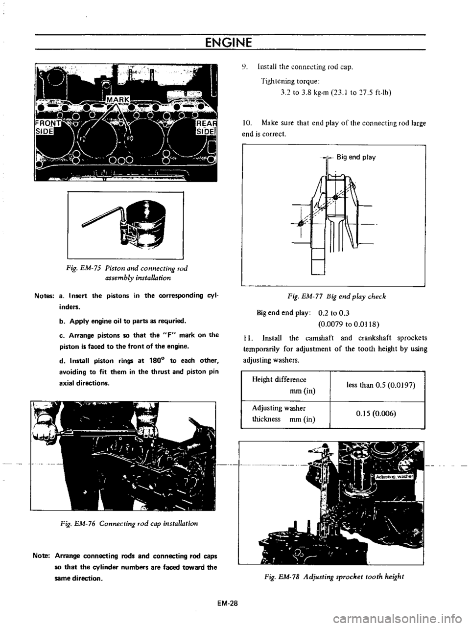
Fig
EM
75
Piston
and
connecting
rod
assembly
installation
Notes
8
I
nsert
the
pistons
in
the
corresponding
cyl
inders
b
Apply
engine
oil
to
parts
as
requried
c
Arrange
pistons
so
that
the
F
mark
on
the
piston
is
faced
to
the
front
of
the
engine
d
Install
piston
rings
at
180
to
each
other
avoiding
to
fit
them
in
the
thrust
and
piston
pin
axial
directions
Fig
EM
76
Connecting
rod
cap
installation
Note
Arrange
connecting
rods
and
connecting
rod
caps
so
that
the
cylinder
numbers
are
faced
toward
the
same
direction
EM
28
q
Install
the
connecting
rod
cap
Tightening
torque
32
to
3
8
kg
m
23
I
to
7
S
ft
lb
10
Make
sure
that
end
play
of
the
connecting
rod
large
end
is
correct
Big
end
play
j
I
Fig
EM
77
Big
end
play
check
Big
end
end
play
0
2
to
0
3
0
0079
to
0
0118
11
Install
the
camshaft
and
crankshaft
sprockets
temporarily
for
adjustment
of
the
tooth
height
by
using
adjusting
washers
Height
difference
mm
in
less
than
O
S
0
0197
Adjusting
washer
thickness
mm
in
O
IS
0
006
Fig
EM
78
Adjusting
sprocket
tooth
height
Page 369 of 513
ENGINE
MECHANICAL
o
Match
mark
Key
groove
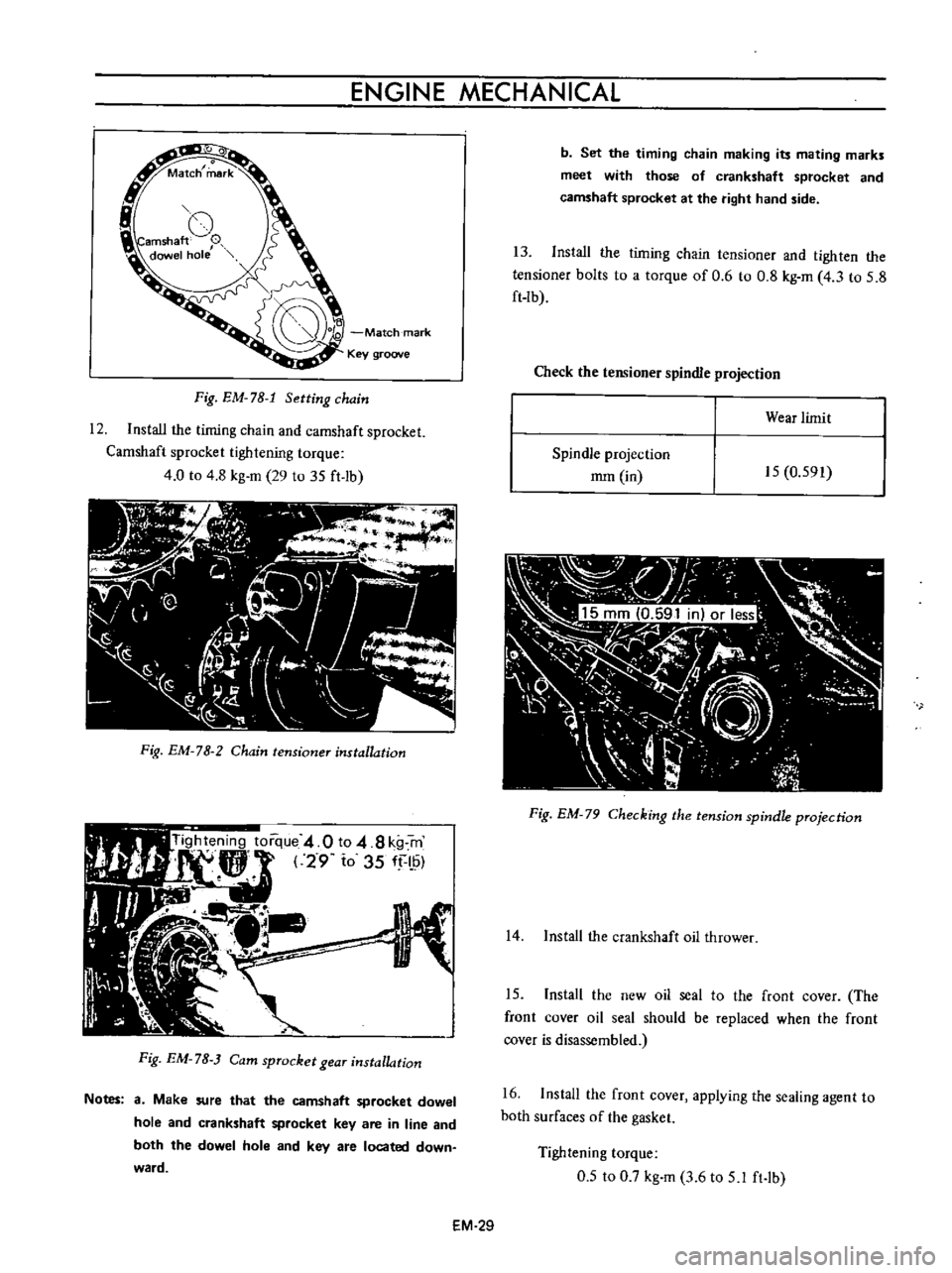
Fig
EM
78
1
Setting
chain
12
Install
the
timing
chain
and
camshaft
sprocket
Camshaft
sprocket
tightening
torque
4
0
to
4
8
kg
m
29
to
35
ft
lb
Fig
EM
78
2
Chain
tensioner
installation
Fig
EM
7B
Cam
sprocket
gear
installation
Notes
a
Make
sure
that
the
camshaft
sprocket
dowel
hole
and
crankshaft
sprocket
key
are
in
line
and
both
the
dowel
hole
and
key
are
located
down
ward
b
Set
the
timing
chain
making
its
mating
marks
meet
with
those
of
crankshaft
sprocket
and
camshaft
sprocket
at
the
right
hand
side
13
Install
the
timing
chain
tensioner
and
tighten
the
tensioner
bolts
to
a
torque
of
0
6
to
0
8
kg
m
4
3
to
5
8
ft
lb
Check
the
tensioner
spindle
projection
Wear
limit
Spindle
projection
mm
in
15
0
591
Fig
EM
79
Checking
the
tension
spindle
projection
14
Install
the
crankshaft
oil
thrower
15
Install
the
new
oil
seal
to
the
front
cover
The
front
cover
oil
seal
should
be
replaced
when
the
front
cover
is
disassembled
16
Install
the
front
cover
applying
the
sealing
agent
to
both
surfaces
of
the
gasket
Tightening
torque
0
5
to
0
7
kg
m
3
6
to
5
1
ft
lb
EM
29
Page 379 of 513
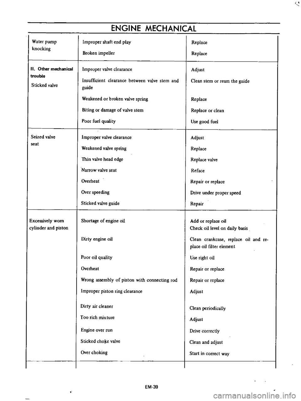
Water
pump
knocking
II
Other
mechanical
trouble
Sticked
valve
Seized
valve
seat
Excessively
worn
cylinder
and
piston
ENGINE
MECHANICAL
Improper
shaft
end
play
Broken
impeller
Improper
valve
clearance
Insufficient
clearance
between
valve
stem
and
guide
Weakened
or
broken
valve
spring
Biting
or
damage
ofvalve
stem
Poor
fuel
quality
Improper
valve
clearance
Weakened
valve
spring
Thin
valve
head
edge
Narrow
valve
seat
Overheat
Over
speeding
Sticked
valve
guide
Shortage
of
engine
oil
Dirty
engine
oil
Poor
oil
quality
Overheat
Wrong
assembly
of
piston
with
connecting
rod
Improper
piston
ring
clearance
Dirty
air
cleaner
Too
rich
mixture
Engine
over
run
Slicked
cho
e
valve
Over
choking
EM
39
Replace
Replace
Adjust
Clean
stem
or
ream
the
guide
Replace
Replace
or
clean
Use
good
fuel
Adjust
Replace
Replace
valve
Reface
Repair
or
replace
Drive
under
proper
speed
Repair
Add
or
replace
oil
Check
oil
level
on
daily
basis
Clean
crankcase
replace
oil
and
re
place
oil
fIlter
element
use
right
oil
Repair
or
replace
Repair
or
replace
Adjust
Clean
periodically
Adjust
Drive
correctly
Clean
and
adjust
Start
in
correct
way
Page 380 of 513
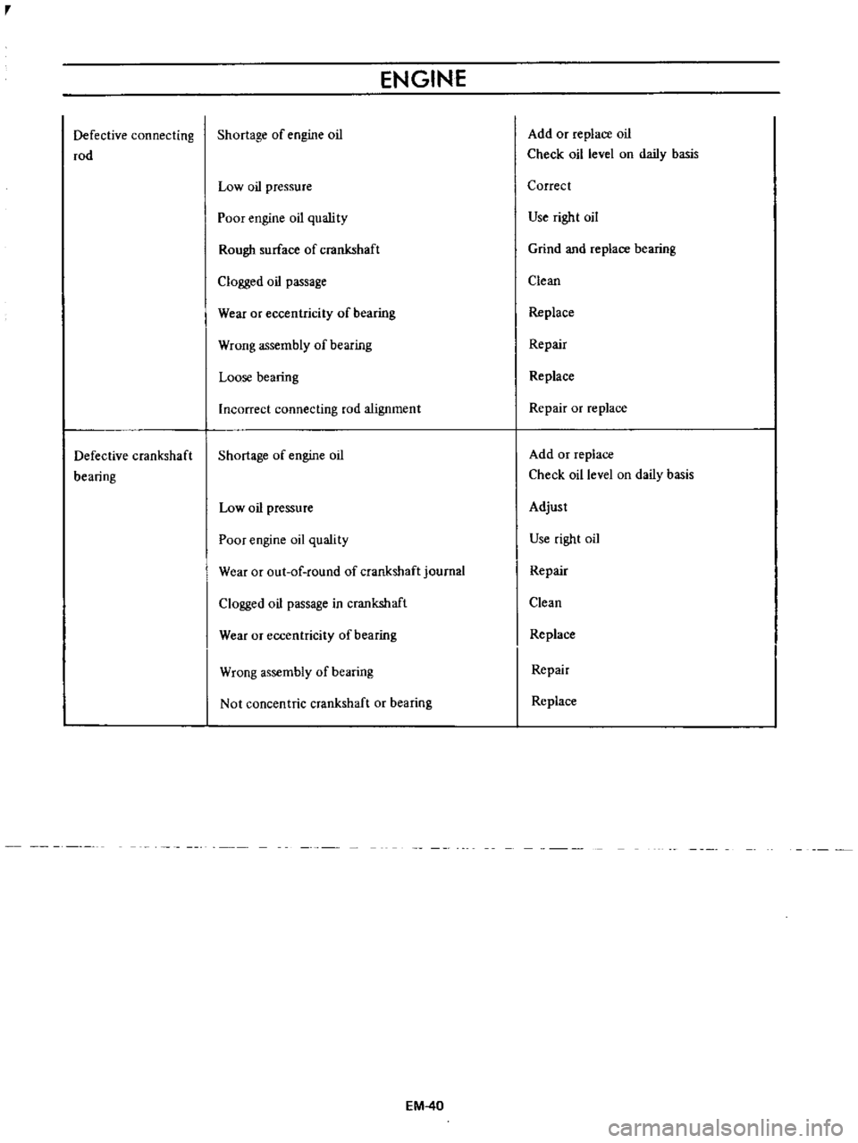
r
Defective
connecting
rod
Defective
crankshaft
bearing
ENGINE
Shortage
of
engine
oil
Low
oil
pressure
Poor
engine
oil
quslity
Rough
surface
of
crankshaft
Clogged
oil
passage
Wear
or
eccentricity
of
bearing
Wrong
assembly
of
bearing
Loose
bearing
Incorrect
connecting
rod
alignment
Shortage
of
engine
oil
Low
oil
pressure
Poor
engine
oil
quality
Wear
or
out
of
round
of
crankshaft
journal
Clogged
oil
passage
in
crankshaft
Wear
or
eccentricity
of
bearing
Wrong
assembly
of
bearing
Not
concentric
crankshaft
or
bearing
EM
40
Add
or
replace
oil
Check
oil
level
on
daily
basis
Correct
Use
right
oil
Grind
and
replace
bearing
Clean
Replace
Repair
Replace
Repair
or
replace
Add
or
replace
Check
oil
level
on
daily
basis
Adjust
Use
right
oil
Repair
Clean
Replace
Repair
Replace
Page 383 of 513
LUBRICATION
CIRCUIT
Oil
drawn
from
the
oil
pan
through
the
inlet
screen
and
tube
to
the
inlet
side
of
the
oil
pump
is
delivered
by
th
oil
pump
through
the
outlet
portion
of
the
oil
pump
and
the
oil
gallery
to
the
inlet
side
of
the
full
flow
oil
filter
and
to
the
main
oil
gallery
The
main
oil
gallery
supplies
oil
to
the
crankshaft
main
bearings
and
drilled
passages
in
the
crankshaft
and
thus
oil
is
fed
directly
from
the
main
bearings
to
the
connecting
rod
bearings
Oil
injected
from
jet
holes
on
connecting
rods
lubri
cates
the
cylinder
walls
and
pistion
pins
The
oil
distributed
from
the
main
gallery
enters
the
chain
teosioner
and
the
pad
is
held
against
the
chain
by
oil
pressure
and
spring
The
oil
also
lubricates
the
timing
chain
through
the
jet
hole
located
near
the
chain
Furthermore
lubricant
is
supplied
to
each
camshaft
bearing
through
each
crankshaft
main
bearing
and
finally
to
the
011
gallery
in
the
rocker
shaft
through
the
center
camshaft
bearing
The
rocker
arm
and
valve
are
lubricated
by
the
oil
through
the
oil
gallery
in
the
rockershaft
To
this
oil
gallery
lubricant
is
supplied
through
the
center
camshaft
bearing
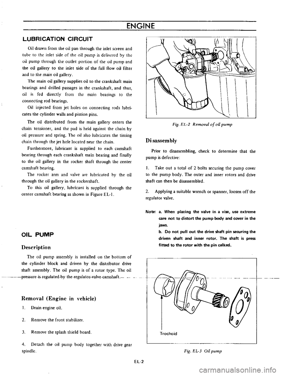
as
shown
in
Figure
EL
I
OIL
PUMP
Description
The
oil
pump
assembly
is
installed
on
the
bottom
of
the
cylinder
block
and
driven
by
the
distributor
drive
shaft
assembly
The
oil
pump
is
of
a
rotor
type
The
oil
pressure
is
regulated
by
the
regulator
valve
camshaft
Removal
Engine
in
vehicle
Drain
engine
oil
2
Remove
the
frunt
stabilizer
3
Remove
the
splash
shield
board
4
Detach
the
oil
pump
body
together
with
drive
gear
spindle
ENGINE
Fig
EL
2
Removal
of
oil
pump
Disassembly
Prior
to
disassembling
check
to
determine
that
the
pump
is
defective
Take
out
a
total
of
2
bolts
securing
the
pump
cover
to
the
pump
body
The
outer
and
inner
rotors
and
drive
shaft
can
then
be
disassembled
2
Applying
a
suitable
wrench
or
spanner
loosen
off
the
regulator
valve
Note
a
When
placing
the
valve
in
a
vise
use
extreme
care
not
to
distort
the
pump
body
and
cover
in
the
jaws
b
Do
not
pull
out
the
drive
shaft
pin
securing
the
driven
shaft
and
inner
rotor
The
shaft
is
press
fitted
to
the
rotor
with
the
pin
calked
n
Trochoid
Fig
EL
Oil
pump
EL
2
Page 384 of 513
ENGINE
LUBRICATION
SYSTEM
Inspection
and
repair
Clean
the
disassembled
parts
with
cleaning
solvent
and
inspect
for
defects
Inspect
the
drive
rotor
shaft
for
excessive
wear
and
scores
and
check
the
following
clearances
Side
clearance
between
Quter
and
inner
rotors
0
12
mm
0
0047
in
or
below
Tip
clearance
0
04
to
0
I2mm
0
0016
to
0
0047
in
Clearance
between
outer
rotor
and
body
0
15
to
0
21
rom
0
0059
to
0
0083
in
Adjusting
regulator
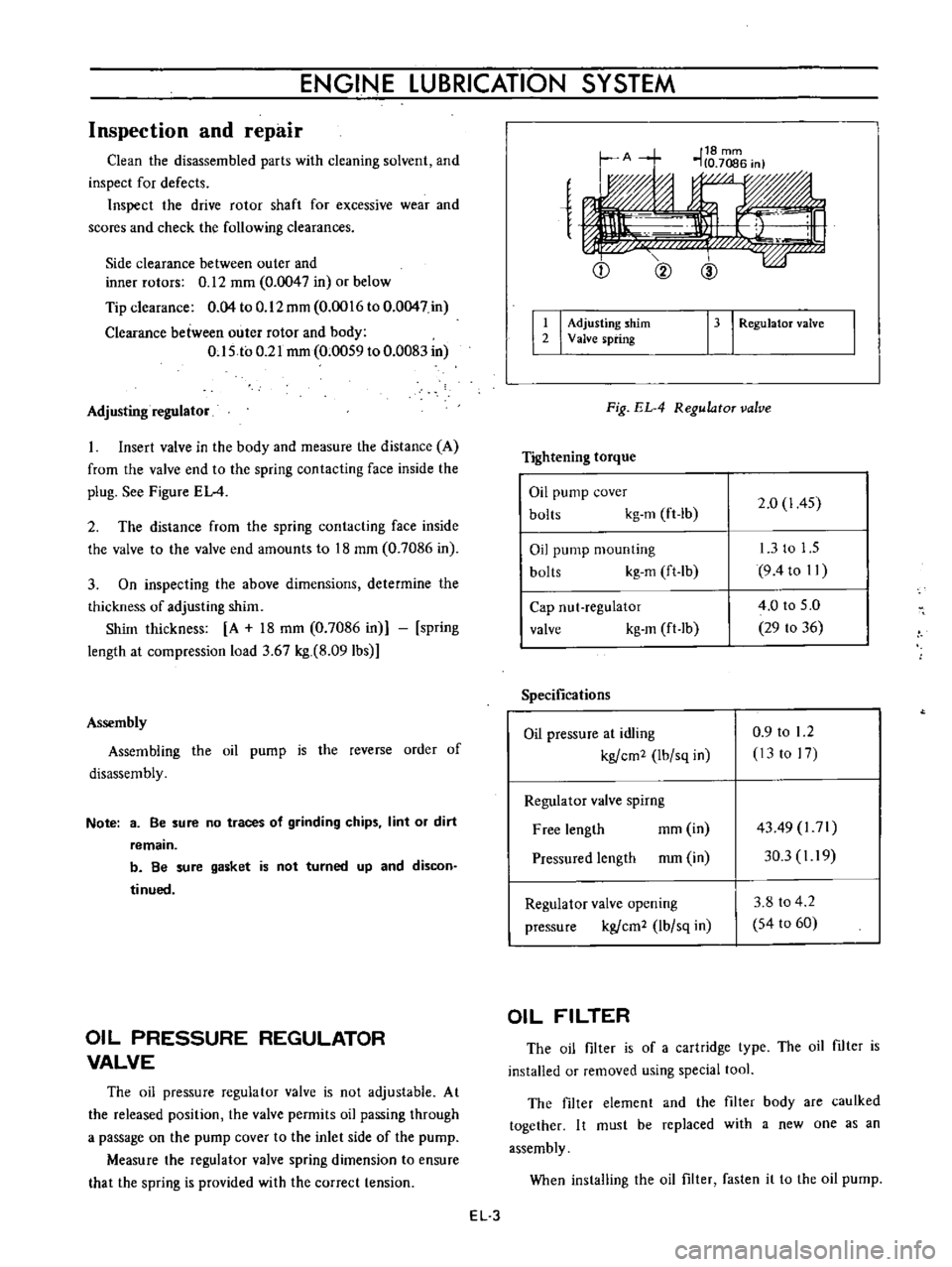
Insert
valve
in
the
body
and
measure
the
distance
A
from
the
valve
end
to
the
spring
contacting
face
inside
the
plug
See
Figure
EL
4
2
The
distance
from
the
spring
contacting
face
inside
the
valve
to
the
valve
end
amounts
to
18
mm
0
7086
in
3
On
inspecting
the
above
dimensions
determine
the
thickness
of
adjusting
shim
Shim
thickness
A
18
mm
0
7086
in
spring
length
at
compression
load
3
67
kg
8
091bs
Assembly
Assembling
the
oil
pump
is
the
reverse
order
of
disassembly
Note
3
Be
sure
no
traces
of
grinding
chips
lint
or
dirt
remain
b
Be
sure
gasket
is
not
turned
up
and
discon
tinued
OIL
PRESSURE
REGULATOR
VALVE
The
oil
pressure
regulator
valve
is
not
adjustable
At
the
released
position
the
valve
permits
oil
passing
through
a
passage
on
the
pump
cover
to
the
inlet
side
of
the
pump
Measure
the
regulator
valve
spring
dimension
to
ensure
that
the
spring
is
provided
with
the
correct
tension
e
Q
@
I
I
Adjusting
shim
2
Valve
spring
13
I
RegulatoT
valve
Fig
EL
4
RegulatoT
valve
Tightening
torque
Oil
pump
cover
bolts
kg
m
ft
lb
2
0
1
45
Oil
pump
mounting
bolts
kg
m
ft
lb
13
to
1
5
9
4to
II
Cap
nut
regulator
valve
kg
m
ft
lb
4
0
to
5
0
29
to
36
Specifications
Oil
pressure
at
idling
kgfcm2
Ibfsq
in
0
9
to
1
2
13
to
17
Regulator
valve
spirng
Free
length
mm
in
Pressured
length
mm
in
4349
l71
30
3
I
19
Regulator
valve
opening
pressure
kgfcm2
lbfsq
in
3
8
to
4
2
54
to
60
OIL
FILTER
The
oil
filter
is
of
a
cartridge
type
The
oil
filter
is
installed
or
removed
using
special
tool
The
filter
element
and
the
filter
body
are
caulked
together
I
t
must
be
replaced
with
a
new
one
as
an
assembly
When
installing
the
oil
filter
fasten
it
to
the
oil
pump
EL
3