Page 485 of 513

CLUTCH
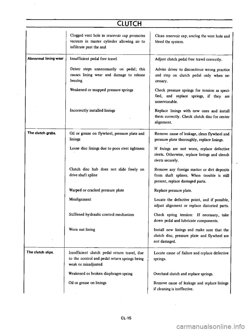
Clogged
vent
hole
in
reservoir
cap
promotes
vacuum
in
master
cylinder
allowing
air
to
inf1ltrate
past
the
seal
Abnormal
lining
wear
Insufficient
pedal
free
travel
The
clutch
grabs
The
clutch
slips
Driver
steps
unnecessarily
on
pedal
this
causes
lin
jog
wear
and
damage
to
release
bearing
Weakened
or
snapped
pressure
springs
Incorrectly
installed
linings
Oil
or
grease
on
flywheel
pressure
plate
and
linings
Loose
disc
linings
due
to
poor
rivet
tightness
Clutch
disc
hub
does
not
slide
freely
on
drive
shaft
spline
Warped
or
cracked
pressure
plate
Misalignment
Stiffened
hydraulic
control
mechanism
Wom
out
lining
Insufficient
clutch
pedal
return
travel
due
to
the
control
and
pedal
return
springs
being
weak
or
misadjusted
Weakened
or
broken
diaphragm
spring
Oil
or
grease
on
linings
eLl5
Clean
reservoir
cap
unclog
the
vent
hole
and
bleed
the
system
Adjust
clutch
pedal
free
travel
correctly
Advise
driver
to
discontinue
wrong
practice
and
step
on
clutch
pedal
only
when
ne
cessary
Check
pressure
springs
for
tension
as
speci
fied
and
replace
springs
if
they
are
unserviceable
Replace
linings
with
new
ones
and
install
them
correctly
Check
clutch
disc
for
center
alignment
Remove
cause
of
leakage
clean
flywheel
and
pressure
plate
thoroughly
replace
linings
If
linings
are
not
worn
replace
defective
rivets
Otherwise
replace
linings
and
clench
rivets
securely
Remove
any
foreign
matter
or
dirt
deposits
from
shaft
splines
When
trouble
is
still
present
replace
damaged
parts
Replace
pressure
plate
Locate
the
defective
point
and
if
possible
adjust
alignment
or
replace
distorted
parts
Check
spring
tension
If
necessary
take
down
pedal
and
lubricate
components
Install
new
linings
and
make
sure
tha
t
the
clutch
disc
pressure
plate
and
flywheel
are
not
damaged
Locate
cause
of
failure
and
replace
defective
springs
Overhaul
clutch
and
replace
springs
Remove
cause
of
leakage
and
replace
linings
if
cleaning
is
ineffective
Page 494 of 513

TRANSMISSION
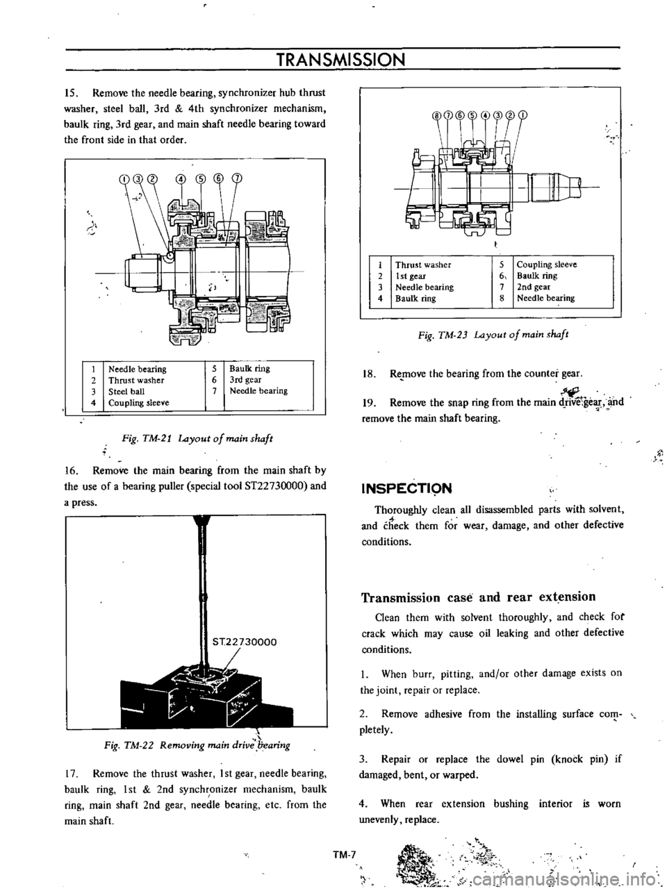
15
Remove
the
needle
bearing
synchronizer
hub
thrust
washer
steel
ball
3rd
4th
synchronizer
mechanism
baulk
ring
3rd
gear
and
main
shaft
needle
bearing
toward
the
front
side
in
that
order
S
b
L
74FE
r
1
Needle
bearing
2
Thrust
washer
3
Steel
ball
4
Coupling
sleeve
5
BauIk
ring
6
3rd
gear
7
Needle
bearing
Fig
TM
21
Layout
of
main
shaft
16
Remove
the
main
bearing
from
the
main
shaft
by
the
use
of
a
bearing
puller
special
tool
ST2273
000
and
a
press
1
ST22730000
r
1
t
Jii
Fig
TM
22
Removing
main
drive
l7earing
17
Remove
the
thrust
washer
I
st
gear
needle
bearing
baulk
ring
1st
2nd
synchronizer
mechanism
baulk
ring
main
shaft
2nd
gear
needle
bearing
etc
from
the
main
shaft
1
2
3
4
5
Coupling
sleeve
6
Baulk
ring
7
2nd
gear
8
Needle
bearing
Thrust
washer
1st
gear
Needle
bearing
Baulk
ring
Fig
TM
23
Layout
of
main
shaft
18
Re
move
the
bearing
from
the
counter
gear
19
Remove
the
snap
ring
from
the
main
ge
f
and
remove
the
main
shaft
bearing
INSPECTI9N
Thoroughly
clean
all
disassembled
parts
with
solvent
and
check
them
for
wear
damage
and
other
defective
conditions
Transmission
case
and
rear
extension
Clean
them
with
solvent
thoroughly
and
check
for
crack
which
may
cause
oil
leaking
and
other
defective
conditions
I
When
burr
pitting
and
or
other
damage
exists
on
the
joint
repair
or
replace
2
Remove
adhesive
from
the
installing
surface
com
pletely
3
Repair
or
replace
the
dowel
pin
knock
pin
if
damaged
bent
or
warped
4
When
rear
extension
bushing
interior
is
worn
unevenly
replace
TM
7
Ii
01
r
Page 495 of 513

I
t
CHASSIS
Bearing
Thoroughly
clean
the
bearing
dry
and
remove
dust
with
compressed
air
2
When
the
ball
bearing
inner
race
and
center
race
ball
sliding
surfaces
are
worn
unevenly
and
or
unsmooth
due
to
crack
or
out
of
round
of
ball
is
excessive
due
to
wear
or
rough
surface
replace
the
bearing
with
a
new
one
6
Fig
TM
24
Inspecting
baa
bearing
f
3
tplace
needle
bearing
if
worn
or
damaged
I
ePlace
rear
extension
bushing
if
worn
or
cracked
r
r
Gear
and
shaft
I
Check
the
gear
for
wear
damage
and
or
crack
and
replace
if
required
2
Check
the
shaft
for
bending
crack
wear
and
worn
spline
and
replace
if
required
1
i
STEP
WEAR
I
TWIST
Fig
TM
25
Checking
main
shaft
spline
for
twisting
0
I
l
lii
j
o
iIk
j
i
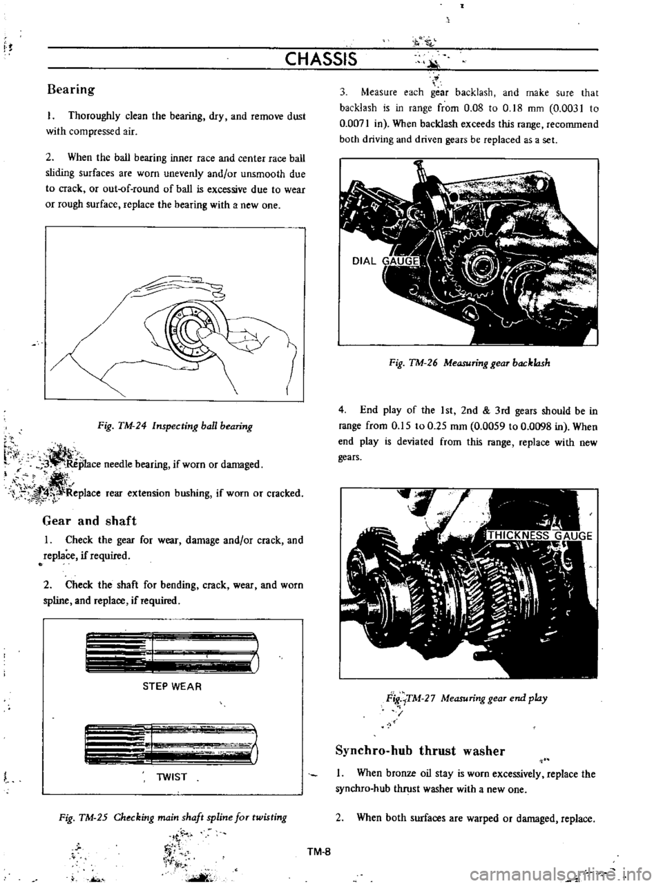
Measure
each
gear
backlash
and
make
sure
that
backlash
is
in
range
from
0
08
to
0
18
mm
0
0031
to
0
0071
in
When
backlash
exceeds
this
range
recommend
both
driving
and
driven
gears
be
replaced
as
a
set
Fig
TM
26
Measuring
gear
backlash
4
End
play
of
the
1st
2nd
3rd
gears
should
be
in
range
from
0
15
to
0
25
mm
0
0059
to
0
0098
in
When
end
play
is
deviated
from
this
range
replace
with
new
gears
Flg
TM
27
Measuring
gear
end
play
i
Synchro
hub
thrust
washer
1
When
bronze
oil
stay
is
worn
excessively
replace
the
synchro
hub
thrust
washer
with
a
new
one
2
When
both
surfaces
are
warped
or
damaged
replace
TM
8
Page 496 of 513

TR
ANSMISSION
Baulk
ring
I
Check
the
baulk
rings
for
wear
pitting
chips
or
burrs
If
any
abnormal
conditions
are
detected
they
must
be
replaced
with
new
ones
2
Place
the
baulk
ring
in
position
on
the
cone
of
each
gear
Push
the
ring
to
the
gear
and
check
the
gap
between
the
end
face
of
the
bauIk
ring
and
the
front
face
of
the
clutch
teeth
This
gap
should
be
within
1
05
to
I
4
mm
0
0413
to
0
0551
in
If
it
is
less
than
0
5
mm
0
0197
in
a
worn
bauIk
ring
may
be
the
cause
and
a
new
ring
should
be
fitted
ii
V
ilillltII
l
A
1
05
to
1
4
mm
0
0413
to
0
0551
in
Fig
TM
28
ulk
ring
to
cone
installing
dimension
ShiftiAg
insert
Replace
if
worn
excessively
worn
unevenly
de
formed
or
damaged
Oil
seal
i
T
l
l
11
tT
Replace
the
oil
seal
with
a
new
one
if
lip
is
deformed
f
worn
or
cracked
or
when
the
spring
is
dropped
off
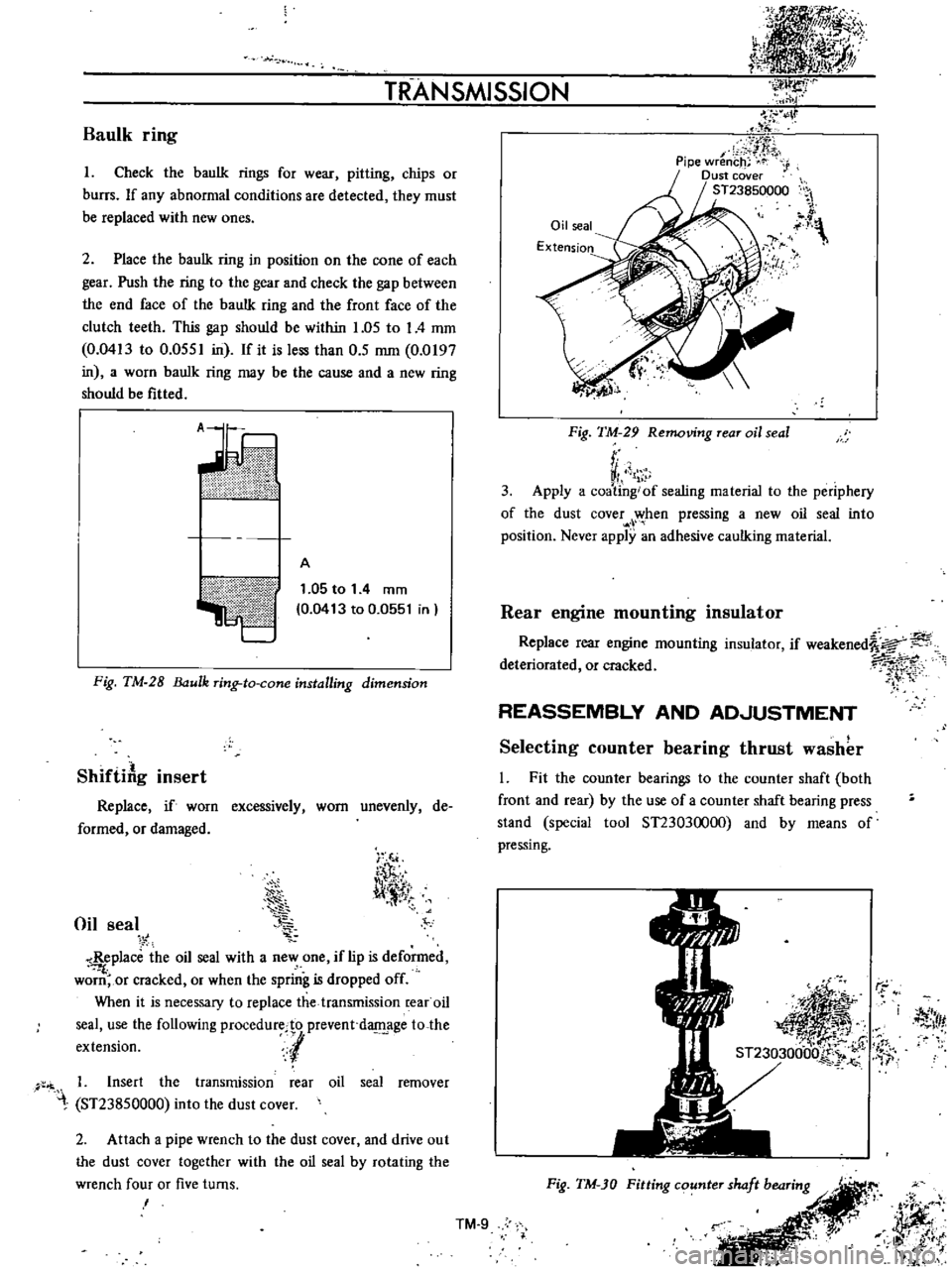
When
it
is
necessary
to
replace
the
transmission
rear
oil
seal
use
the
following
procedurecto
prevent
d
age
to
the
extension
l
1
Insert
the
transmission
rear
oil
seal
remover
ST23850000
into
the
dust
cover
2
Attach
a
pipe
wrench
to
the
dust
cover
and
drive
out
the
dust
cover
together
with
the
oil
seal
by
rotating
the
wrench
four
or
five
turns
I
Oil
seal
Extension
IJ
y
Fig
TM
29
Removing
rear
oil
seal
r
VI
1
3
Apply
a
coating
of
sealing
material
to
the
periphery
of
the
dust
cover
when
pressing
a
new
oil
seal
into
position
Never
apply
an
adhesive
caulking
material
Rear
engine
mounting
insulator
Replace
rear
engine
mounting
insulator
if
weakened
a
deteriorated
or
cracked
7i
1
rt
REASSEMBLY
AND
AD
JUSTMENT
Selecting
counter
bearing
thrust
washer
l
Fit
the
counter
bearings
to
the
counter
shaft
both
front
and
rear
by
the
use
of
a
counter
shaft
bearing
press
stand
special
tool
ST23030000
and
by
means
of
pressing
r
j
Itf
Fig
TM
JO
Fitting
counter
shaft
bearing
r
JJff
i
it
l
t
i
j
IlK
Ji
t
l
k
TM
9