1973 DATSUN B110 check oil
[x] Cancel search: check oilPage 63 of 513
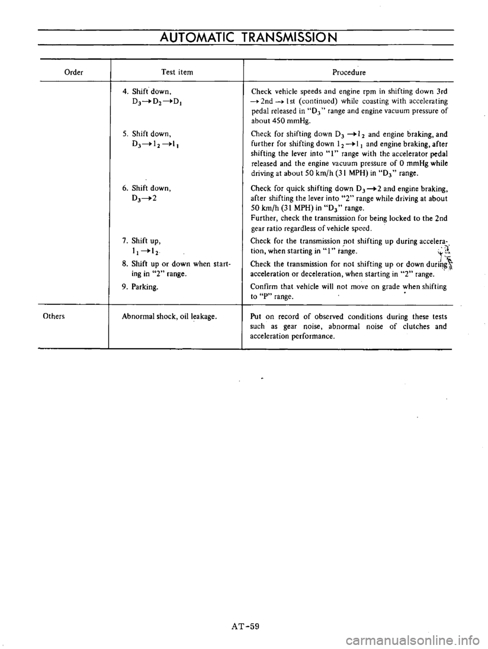
Order
Others
AUTOMATIC
TRANSMISSION
Test
item
4
Shift
down
Dr4D2
DI
5
Shift
down
DJ
I2
l
6
Shift
down
DJ
2
7
Shift
up
I
12
8
Shift
up
or
down
when
start
ing
in
2
range
9
Parking
Abnormal
shock
oil
leakage
Procedure
Check
vehicle
speeds
and
engine
rpm
in
shifting
down
3rd
2nd
I
st
continued
while
coasting
with
acceleraling
pedal
released
in
0
range
and
engine
vacuum
pressure
of
about
450
mmHg
Check
for
shifting
down
DJ
12
and
engine
braking
and
further
for
shifting
down
12
11
and
engine
braking
after
shifting
the
lever
into
I
range
with
the
accelerator
pedal
released
and
the
engine
vacuum
pressure
of
0
mmHg
while
driving
at
about
SO
km
h
31
MPH
in
DJ
range
Check
for
quick
shifting
down
DJ
2
and
engine
braking
after
shifting
the
lever
into
2
range
while
driving
at
about
50
km
h
31
MPH
in
DJ
range
Further
check
the
transmission
for
being
locked
to
the
2nd
gear
ratio
regardless
of
vehicle
speed
Check
for
the
transmission
not
shifting
up
during
acceIera
tion
when
starting
in
1
t
nge
It
Check
the
transmission
for
not
shifting
up
or
down
durih
t
acceleration
or
deceleration
when
starting
in
2
range
Confirm
that
vehicle
will
not
move
on
grade
when
shifting
to
P
range
Put
on
record
of
observed
conditions
during
these
tests
such
as
gear
noise
abnormal
noise
of
clutches
and
acceleration
performance
AT
59
Page 72 of 513

PROPELLER
SHAFT
DIFFERENTIAL
CARRIER
The
gear
carrier
is
made
of
light
and
strong
aluminum
alloy
metal
and
hypoid
bevel
gear
is
used
Adjust
drive
pinion
bearing
preload
with
non
adjusting
type
spacer
and
pinion
height
and
side
bearing
adjust
ment
with
spacer
shim
s
Millimeter
standardization
stilI
remains
for
all
the
screw
threads
of
this
unit
Therefore
adjustment
figures
stamped
on
screws
adjusting
shims
washers
differential
case
drive
pinion
and
carrier
are
in
millimeters
in
accordance
with
the
millimeter
standardization
of
parts
The
proper
lubrication
to
the
gear
housing
is
necessary
otherwise
it
would
shorten
the
durability
of
the
gear
and
cause
other
troubles
The
lubricant
should
be
checked
each
5
000
km
3
000
miles
and
replenished
each
50
000
km
30
000
miles
The
lubricant
should
be
drained
and
ref11led
at
the
end
of
the
first
1
000
km
600
miles
to
eliminate
any
loose
material
from
the
sump
which
results
from
breaking
Differential
lubricant
should
be
changed
at
least
every
50
000
km
30
000
miles
ConsIderations
should
be
given
to
the
following
matters
I
Nominated
hypoid
gear
oil
must
be
used
2
It
is
prohibited
to
use
any
gear
oil
of
different
viscosity
The
same
brand
must
always
be
selected
3
The
standard
oil
capacity
is
about
0
75
liter
0
198
US
gal
REMOVAL
Fig
PD
5
Removing
differential
gear
carrier
To
remove
the
gear
carrier
assembly
disconnect
the
drive
pinion
companion
flange
te
flange
yoke
connection
and
remove
two
rear
axle
shafts
Refer
to
REAR
AXLE
for
the
work
DISASSEMBLY
I
Install
the
gear
carrier
assembly
on
the
Gear
Carrier
Attachment
ST06320000
ST06320000
Fig
PD
6
Holding
differential
camer
2
Inspect
the
following
before
disassembling
I
Inspect
the
tooth
contact
pattern
with
a
lead
oxide
2
Measure
backlash
between
drive
gear
and
pinion
gear
using
a
dial
indicator
3
Put
match
mark
on
one
side
of
the
side
bearing
cap
by
the
use
of
a
punch
SIDCBEMING
c
e
Fig
PD
7
Putting
mark
PD
5
Page 75 of 513
CHASSIS
Before
inspecting
various
parts
thoroughly
wash
them
so
that
damage
and
wear
can
be
easily
detected
Then
proceed
as
follows
Check
gear
teeth
for
scoring
cracking
and
chipping
and
make
sure
that
tooth
pattern
indicates
correct
meshing
depth
If
any
defect
is
evident
replace
parts
as
required
Note
Drive
pinion
and
drive
gear
are
supplied
for
replacement
as
a
set
therefore
should
either
part
be
damaged
replace
as
a
set
Check
the
pinion
gear
shaft
and
pinion
gear
mating
faces
for
scoring
and
signs
of
wear
and
replace
as
required
Follow
the
same
procedure
for
inner
faces
of
side
gear
and
their
seats
on
differential
case
3
Inspect
all
bearing
races
and
rollers
for
scoring
chipping
or
evidence
of
excessive
wear
They
should
be
in
tiptop
condition
not
worn
with
mirror
like
surfaces
Replace
if
there
is
a
doubt
on
their
efficiency
since
an
incorrect
bearing
operation
may
result
in
noisiness
and
gear
seizure
4
Inspect
thrust
washer
faces
Small
defects
can
be
corrected
with
emery
paper
In
ASSEMBLY
AND
AD
JUSTMENT
Tightening
torque
of
side
bearing
cap
bolts
5
to
6kg
m
36
2
to
43
4
ft
lb
co
g
E
E
on
N
case
the
clearance
between
the
side
gear
and
thrust
washer
exceeds
0
2
mm
0
0079
in
replace
the
thrust
washers
Three
kinds
of
thrust
washers
are
available
5
Measure
run
out
of
the
drive
gear
at
the
rear
side
using
a
dial
indicator
When
the
run
out
is
more
0
05
mm
0
0020
in
replace
the
drive
gear
and
pinion
gear
as
a
set
Fig
PD
15
Measuring
run
out
of
drive
gear
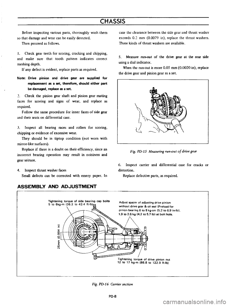
6
Inspect
carrier
and
differential
case
for
cracks
or
distortion
Replace
defective
parts
as
required
Adjust
spacer
of
adjusting
drive
pinion
without
drive
gear
oil
seal
Preload
for
pinion
bearing
6
to
8
kg
em
5
2
to
6
9
in
Ib
1
9
to
2
6
kg
4
2
to
5
7
Ib
at
bolt
hole
1
Tightening
torque
of
drive
pinion
nut
12
to
17
kg
m
86
8
to
122
9
ft
Ibl
Fig
PD
16
Carrier
section
PO
8
Page 78 of 513
PROPELLER
SHAFT
DIFFERENTIAL
CARRIER
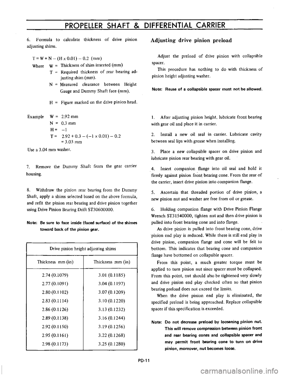
6
Formula
to
calculate
thickness
of
drive
pinion
adjusting
shims
T
W
N
H
x
0
01
0
2
mm
Where
W
Thickness
of
shim
inserted
mm
T
Required
thickness
of
rear
bearing
ad
justing
shim
mm
N
Measured
clearance
between
Height
Gauge
and
Dummy
Shaft
face
mm
H
Figure
marked
on
the
drive
pinion
head
Example
W
2
92
mm
N
0
3
mm
H
1
T
2
92
0
3
1
x
0
01
0
2
3
03
mm
Use
a
3
04
mm
washer
7
Remove
the
Dummy
Shaft
from
the
gear
carrier
housing
8
Withdraw
the
pinion
rear
bearing
from
the
Dummy
Shaft
apply
a
shims
selected
based
on
the
above
formula
and
refit
the
pinion
rear
bearing
and
drive
pinion
together
using
Drive
Pinion
Bearing
Drift
STJ0600000
Note
Be
sure
to
face
inside
faced
surface
of
the
shimes
toward
back
of
the
pinion
gear
Drive
pinion
height
adjusting
shims
Thickness
mm
in
Thickness
mm
in
2
74
0
1079
2
77
0
i091
2
80
0
1102
2
83
0
1114
2
86
0
1126
2
89
0
1138
2
92
0
1150
2
95
0
1161
2
98
0
1173
3
01
0
1185
3
04
0
1197
3
07
0
1209
3
10
0
i
220
3
13
0
1232
3
16
0
1244
319
0
1256
3
22
0
1268
3
25
0
1280
PD
Adjusting
drive
pinion
preload
Adjust
the
preload
of
drive
pinion
with
collapsible
spacer
This
procedure
has
nothing
to
do
with
thickness
of
pinion
height
adjusting
washer
Note
Reuse
of
a
collapsible
spacer
must
not
be
allowed
After
adjusting
pinion
height
lubricate
front
bearing
with
gear
oil
and
place
it
in
carrier
2
Install
a
new
oil
seal
in
carrier
Lubricate
cavity
between
seal
lips
with
grease
when
installing
3
Place
a
new
collapsible
spacer
on
drive
pinion
and
lubricate
pinion
rear
bearing
with
gear
oil
4
Insert
companion
flange
into
oil
seal
and
hold
it
firmly
against
pinion
fron
bearing
cone
From
the
rear
of
the
carrier
insert
drive
pinion
into
companion
flange
5
Ascertain
that
threaded
portion
of
drive
pinion
a
new
pinion
nut
and
washer
are
free
from
oil
or
grease
6
Holding
companion
flange
with
Drive
Pinion
Flange
Wrench
ST31540000
tighten
nut
and
then
drive
pinion
is
pulled
into
front
bearing
cone
and
into
flange
As
drive
pinion
is
pulled
into
front
bearing
cone
drive
pinion
end
play
is
reduced
While
there
is
still
end
play
in
drive
pinion
companion
flange
and
cone
will
be
felt
to
bottom
This
indicates
that
bearing
cone
and
companion
flange
have
bottomed
on
collapsible
spacer
From
this
point
a
much
greater
torque
must
be
applied
to
turn
pinion
nut
since
spacer
must
be
collapsed
From
this
point
nut
should
also
be
tightened
very
slowly
and
drive
pinion
end
play
checked
often
so
that
pinion
bearing
preload
does
not
exceed
the
limits
When
the
drive
pinion
end
play
is
eliminated
the
specified
preload
is
being
approached
Replace
collapsible
spacer
if
this
specification
is
exceeded
Note
Do
not
decrease
preload
by
loosening
pinion
nut
This
will
remove
compression
between
pinion
front
and
rear
bearing
cones
and
collapsible
spacer
and
may
permit
front
bearing
cone
to
turn
on
drive
pinion
moreover
nut
becomes
loose
Page 81 of 513
CHASSIS
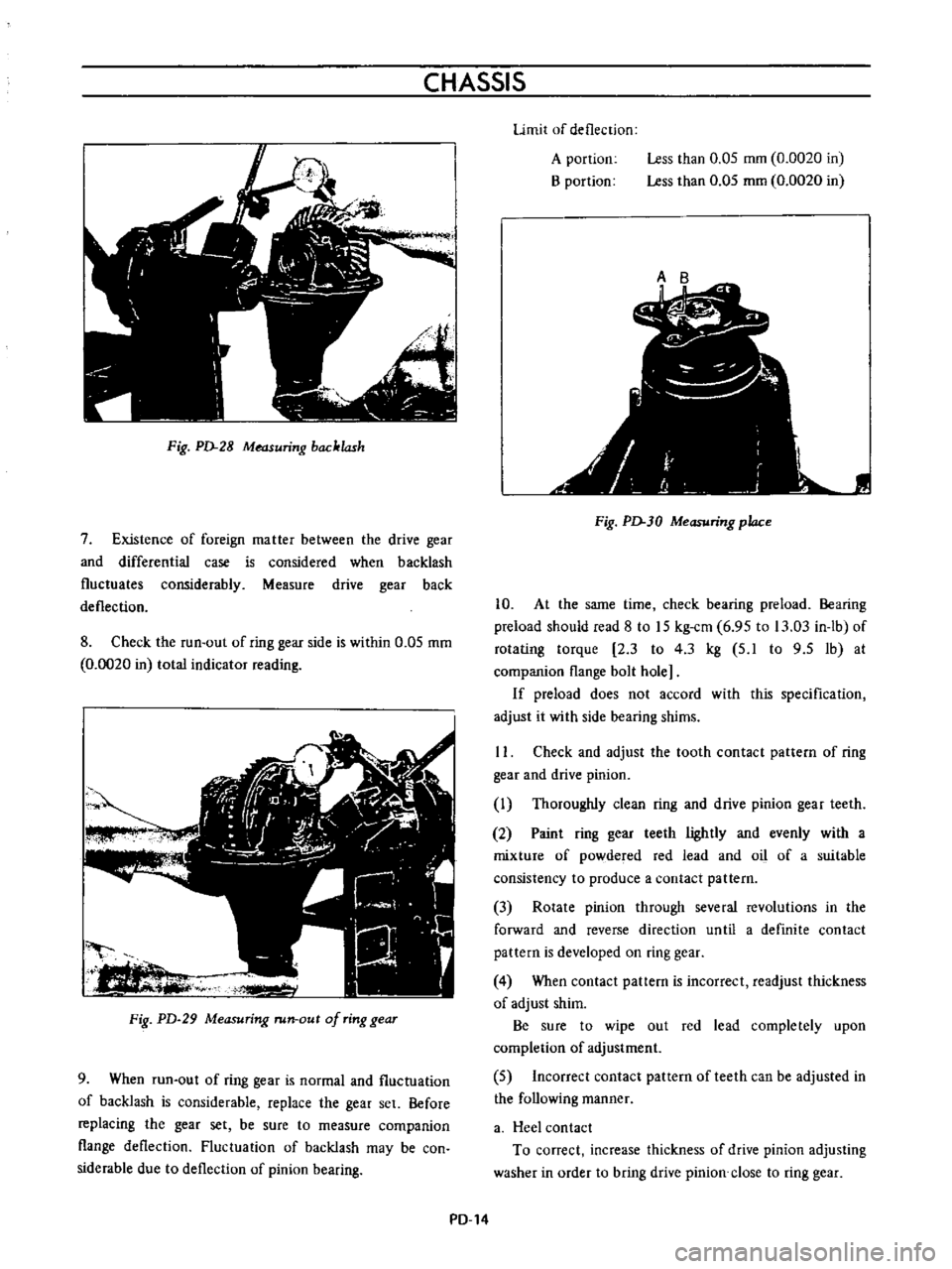
Fig
PD
28
Measuring
backlash
7
Existence
of
foreign
matter
between
the
drive
gear
and
differential
case
is
considered
when
backlash
fluctuates
considerably
Measure
drive
gear
back
deflection
8
Check
the
run
out
of
ring
gear
side
is
within
0
05
mm
0
0020
in
total
indicator
reading
ot
Fig
PD
29
Measuring
run
out
of
ring
gear
9
When
run
out
of
ring
gear
is
normal
and
fluctuation
of
backlash
is
considerable
replace
the
gear
set
Before
replacing
the
gear
set
be
sure
to
measure
companion
flange
deflection
Fluctuation
of
backlash
may
be
con
siderable
due
to
deflection
of
pinion
bearing
Limit
of
deflection
A
portioo
B
portion
Less
than
0
05
mm
0
0020
in
Less
than
0
05
mm
0
0020
in
Ct
r
r
f
1
I
f
i
r
I
oj
j
12
r
Fig
PD
30
Measuring
place
10
At
the
same
time
check
bearing
preload
Bearing
preload
should
read
8
to
15
kg
cm
6
95
to
13
03
in
lb
of
rotating
torque
2
3
to
4
3
kg
5
1
to
9
5
1b
at
companion
flange
bolt
hole
If
preload
does
not
accord
with
this
specification
adjust
it
with
side
bearing
shims
II
Check
and
adjust
the
tooth
contact
pattern
of
ring
gear
and
drive
pinion
I
Thoroughly
clean
ring
and
drive
pinion
gear
teeth
2
Paint
ring
gear
teeth
lightly
and
evenly
with
a
mixture
of
powdered
red
lead
and
oil
of
a
suitable
consistency
to
produce
a
contact
pattern
3
Rorate
pinion
through
several
revolutions
in
the
forward
and
reverse
direction
until
a
definite
contact
pattern
is
developed
on
ring
gear
4
When
contact
pattern
is
incorrect
readjust
thickness
of
adjust
shim
Be
sure
to
wipe
out
red
lead
completely
upon
completion
of
adjustment
5
Incorrect
contact
pattern
of
teeth
can
be
adjusted
in
the
following
manner
a
Heel
contact
To
correct
increase
thickness
of
drive
pinion
adjusting
washer
in
order
to
bring
drive
pinion
close
to
ring
gear
PD
14
Page 100 of 513
CHASSIS
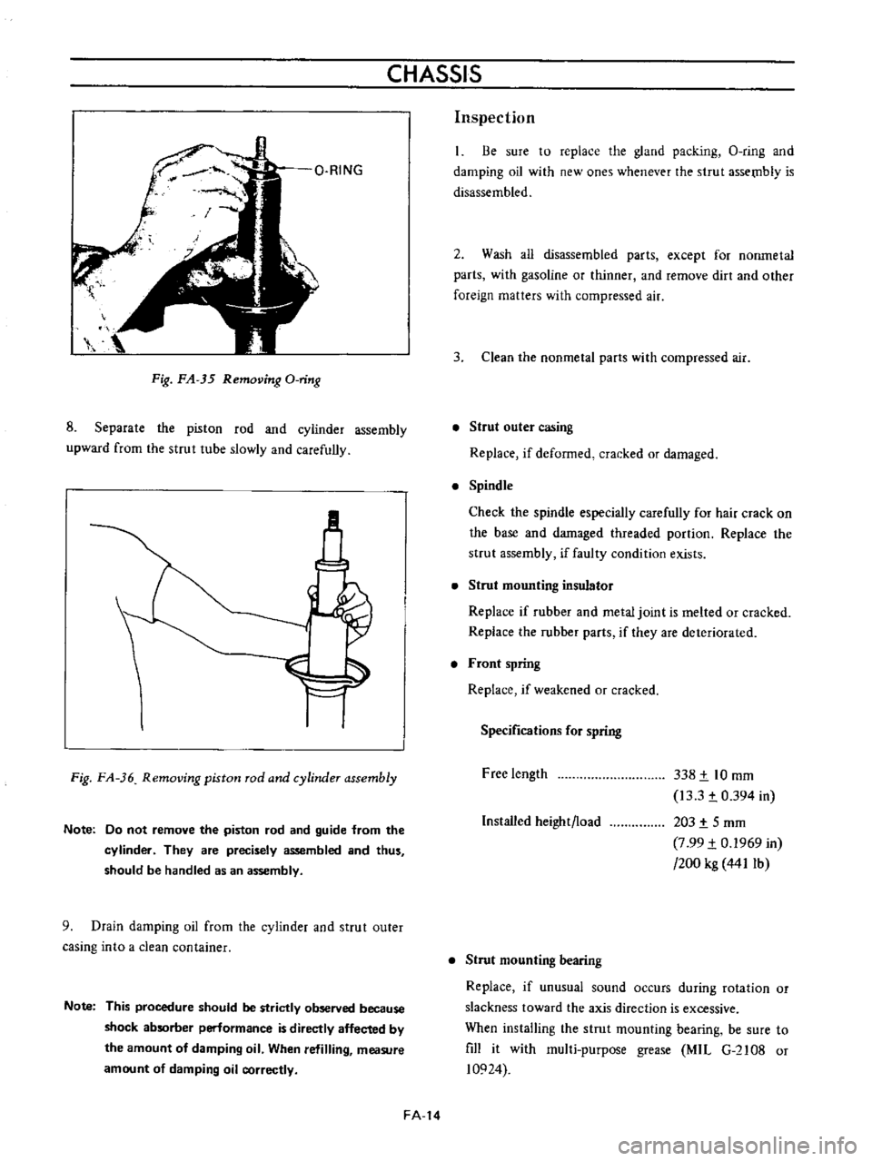
Fig
FA
35
Removing
O
ring
8
Separate
the
piston
rod
and
cyiinder
assembly
upward
from
the
strut
tube
slowly
and
carefully
M
Fig
FA
36
Removing
piston
rod
and
cylinder
assembly
Note
Do
not
remove
the
piston
rod
and
guide
from
the
cylinder
They
are
precisely
assembled
and
thus
should
be
handled
as
an
assembly
9
Drain
damping
oil
from
the
cylinder
and
strut
outer
casing
into
a
clean
container
Note
This
procedure
should
be
strictly
observed
because
shock
absorber
perlormance
is
directly
affected
by
the
amount
of
damping
oil
When
refilling
measure
amount
of
damping
oil
correctly
FA
14
Inspection
Be
sure
to
replace
the
gland
packing
O
ring
and
damping
oil
with
new
ones
whenever
the
strut
assetnb1y
is
disassembled
2
Wash
all
disassembled
parts
except
for
nonmetal
parts
with
gasoline
or
thinner
and
remove
dirt
and
other
foreign
matters
with
compressed
air
3
Clean
the
nonmetal
parts
with
compressed
air
Strut
outer
casing
Replace
if
deformed
cracked
or
damaged
Spindle
Check
the
spindle
especially
carefully
for
hair
crack
on
the
base
and
damaged
threaded
portion
Replace
the
strut
assembly
if
faulty
condition
exists
Strut
mounting
insulator
Replace
if
rubber
and
metal
joint
is
melted
or
cracked
Replace
the
rubber
parts
if
they
are
deteriorated
Front
spring
Replace
if
weakened
or
cracked
Specifications
for
spring
Free
length
338
t
10
mm
13
3
t
0
394
in
203
t
5
mm
7
99
t
0
1969
in
200
kg
441Ib
Installed
height
load
Strut
mounting
bearing
Replace
if
unusual
sound
occurs
during
rotation
or
slackness
toward
the
axis
direction
is
excessive
When
installing
the
strut
mounting
bearing
be
sure
to
fill
it
with
mul1i
purpose
grease
MIL
G
2108
or
10924
Page 118 of 513
REAR
AXLE
REAR
SUSPENSION
y
Jo
r
J
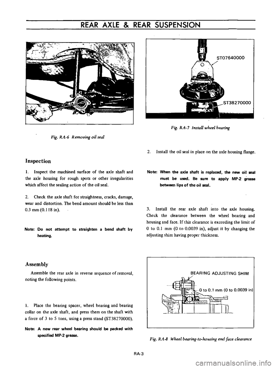
Fig
RA
6
Removing
oil
seal
Inspection
I
Inspect
the
machined
surface
of
the
axle
shaft
and
the
axle
housing
for
rough
spots
or
other
irregularities
which
affect
the
sealing
action
of
the
oil
seal
2
Check
the
axle
shaft
for
straightness
cracks
damage
wear
and
distortion
The
bend
amount
should
be
less
than
0
3
mm
0
118
in
Note
Do
not
attempt
to
straighten
a
bend
shaft
by
heating
Assembly
Assemble
the
rear
axle
in
reverse
sequence
of
removal
noting
the
following
points
I
Place
the
bearing
spacer
wheel
bearing
and
bearing
collar
on
the
axle
shaft
and
press
them
on
the
shaft
with
a
force
of
3
to
5
tons
using
a
press
stand
ST38270000
Note
A
new
rear
wheel
bearing
should
be
packed
with
specified
MP
2
grease
Fig
RA
7
Install
wheel
bearing
2
Install
the
oil
seai
in
place
on
the
axle
housing
flange
Note
When
the
axle
shaft
is
replaced
the
new
oil
seal
must
be
used
Be
sure
to
apply
MP
2
grease
between
lips
of
the
oil
seal
3
Install
the
rear
axle
shaft
into
the
axle
housing
Check
the
clearance
between
the
wheel
bearing
and
housing
and
face
If
this
clearance
is
exceeding
the
limit
of
o
to
0
1
mm
0
to
0
0039
in
adjust
it
by
changing
the
adjusting
shim
having
proper
thickness
BEARING
ADJUSTING
SHIM
1
Fig
RA
8
Wheel
bearing
to
housing
end
face
clearance
RA
3
Page 127 of 513
BRAKE
TANDEM
MASTER
CYLINDER
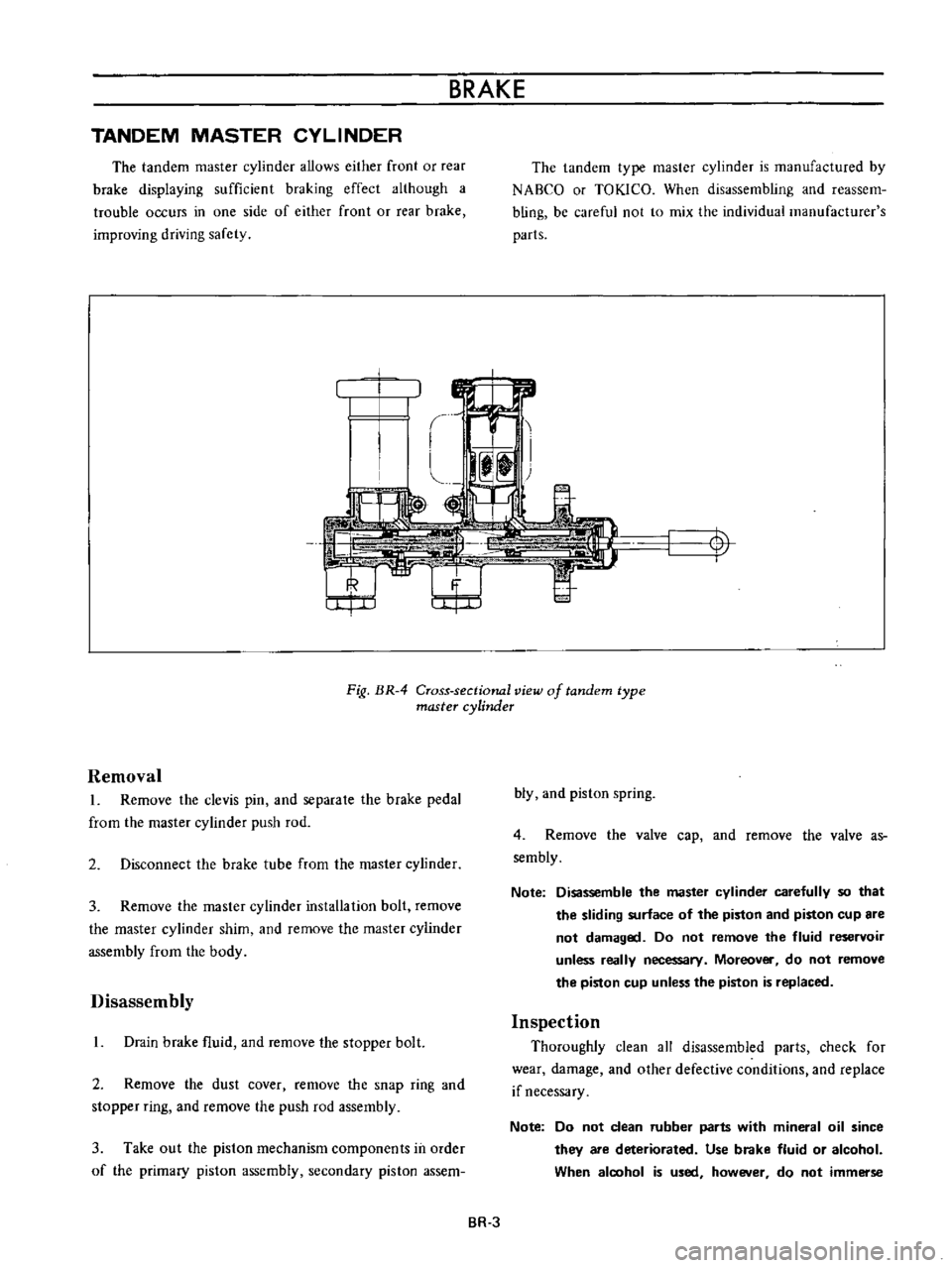
The
tandem
master
cylinder
allows
either
front
or
rear
brake
displaying
sufficient
braking
effect
although
a
trouble
occurs
in
one
side
of
either
front
or
rear
brake
improving
driving
safety
The
tandem
type
master
cylinder
is
manufactured
by
NABCO
or
TOKlCO
When
disassembling
and
reassem
bling
be
careful
not
to
mix
the
individual
manufacturer
s
parts
t
I
Fig
BR
4
Cross
sectional
view
of
tandem
type
master
cylinder
Removal
L
Remove
the
clevis
pin
and
separale
the
brake
pedal
from
the
master
cylinder
push
rod
2
Disconnect
the
brake
tube
from
the
master
cylinder
3
Remove
the
master
cylinder
installation
bolt
remove
the
master
cylinder
shim
and
remove
the
master
cylinder
assembly
from
the
body
Disassembly
L
Drain
brake
fluid
and
remove
the
stopper
bolt
2
Remove
the
dust
cover
remove
the
snap
ring
and
stopper
ring
and
remove
the
push
rod
assembly
3
Take
out
the
piston
mechanism
components
in
order
of
the
primary
piston
assembly
secondary
piston
assem
bly
and
piston
spring
4
Remove
the
valve
cap
and
remove
the
valve
as
sembly
Note
Disassemble
the
master
cylinder
carefully
so
that
the
sliding
surface
of
the
piston
and
piston
cup
are
not
damaged
Do
not
remove
the
fluid
reservoir
unless
really
necessary
Moreover
do
not
remove
the
piston
cup
unless
the
piston
is
replaced
Inspection
Thoroughly
clean
all
disassembled
parts
check
for
wear
damage
and
other
defective
conditions
and
replace
if
necessary
Note
Do
not
clean
rubber
parts
with
mineral
oil
since
they
are
deteriorated
Use
brake
fluid
or
alcohol
When
aloohol
is
used
however
do
not
immerse
BR
3