1973 DATSUN B110 length
[x] Cancel search: lengthPage 377 of 513
ENGINE
MECHANICAL
Piston
diameter
standard
mm
in
Oversize
50
mm
in
Oversize
100
mm
in
Oversize
150
mm
in
Ellipse
difference
mm
in
Ring
groove
width
Top
2nd
Oil
mm
in
Piston
to
bore
clearance
mm
in
g
Piston
pin
Pin
diameter
mm
in
Pin
length
mm
in
Piston
pin
to
piston
clearance
mm
in
Interference
fit
of
piston
pin
to
connecting
rod
bushing
mm
in
h
Piston
ring
Ring
height
Top
2nd
Oil
mm
in
Side
clearance
mm
in
Top
2nd
Oil
Ring
gap
mm
in
Top
2nd
Oil
EM
37
72
967
to
73
017
2
8727
to
2
8747
73
467
to
73
517
2
8924
to
2
8944
73
967
to
74
017
2
9121
to
2
9140
74
467
to
74
517
2
9318
to
2
9337
0
01
to
0
03
0
0004
to
0
0012
2
0
0
0787
2
0
0
0787
4
0
0
1575
0
023
to
0
043
0
0009
to
0
0017
17
447
to
17
452
0
6869
to
0
6871
0
6869
to
0
6871
65
23
to
65
48
2
5681
to
2
5779
0
006
to
0
008
0
0002
to
0
0003
at
200e
680
F
0
017
to
0
034
0
0007
to
0
0013
2
0
0
0787
2
0
0
0787
4
0
0
1575
0
04
to
0
07
0
0016
to
0
0027
0
04
to
0
07
0
0016
to
0
0027
0
04
to
0
08
0
0016
to
0
0031
0
2
to
0
35
0
0079
to
0
0138
0
2
to
0
35
0
0079
to
0
0138
0
3
to
0
90
0
0118
to
0
0354
Page 384 of 513
ENGINE
LUBRICATION
SYSTEM
Inspection
and
repair
Clean
the
disassembled
parts
with
cleaning
solvent
and
inspect
for
defects
Inspect
the
drive
rotor
shaft
for
excessive
wear
and
scores
and
check
the
following
clearances
Side
clearance
between
Quter
and
inner
rotors
0
12
mm
0
0047
in
or
below
Tip
clearance
0
04
to
0
I2mm
0
0016
to
0
0047
in
Clearance
between
outer
rotor
and
body
0
15
to
0
21
rom
0
0059
to
0
0083
in
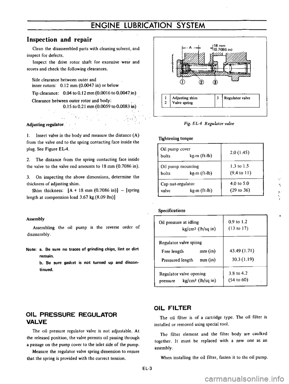
Adjusting
regulator
Insert
valve
in
the
body
and
measure
the
distance
A
from
the
valve
end
to
the
spring
contacting
face
inside
the
plug
See
Figure
EL
4
2
The
distance
from
the
spring
contacting
face
inside
the
valve
to
the
valve
end
amounts
to
18
mm
0
7086
in
3
On
inspecting
the
above
dimensions
determine
the
thickness
of
adjusting
shim
Shim
thickness
A
18
mm
0
7086
in
spring
length
at
compression
load
3
67
kg
8
091bs
Assembly
Assembling
the
oil
pump
is
the
reverse
order
of
disassembly
Note
3
Be
sure
no
traces
of
grinding
chips
lint
or
dirt
remain
b
Be
sure
gasket
is
not
turned
up
and
discon
tinued
OIL
PRESSURE
REGULATOR
VALVE
The
oil
pressure
regulator
valve
is
not
adjustable
At
the
released
position
the
valve
permits
oil
passing
through
a
passage
on
the
pump
cover
to
the
inlet
side
of
the
pump
Measure
the
regulator
valve
spring
dimension
to
ensure
that
the
spring
is
provided
with
the
correct
tension
e
Q
@
I
I
Adjusting
shim
2
Valve
spring
13
I
RegulatoT
valve
Fig
EL
4
RegulatoT
valve
Tightening
torque
Oil
pump
cover
bolts
kg
m
ft
lb
2
0
1
45
Oil
pump
mounting
bolts
kg
m
ft
lb
13
to
1
5
9
4to
II
Cap
nut
regulator
valve
kg
m
ft
lb
4
0
to
5
0
29
to
36
Specifications
Oil
pressure
at
idling
kgfcm2
Ibfsq
in
0
9
to
1
2
13
to
17
Regulator
valve
spirng
Free
length
mm
in
Pressured
length
mm
in
4349
l71
30
3
I
19
Regulator
valve
opening
pressure
kgfcm2
lbfsq
in
3
8
to
4
2
54
to
60
OIL
FILTER
The
oil
filter
is
of
a
cartridge
type
The
oil
filter
is
installed
or
removed
using
special
tool
The
filter
element
and
the
filter
body
are
caulked
together
I
t
must
be
replaced
with
a
new
one
as
an
assembly
When
installing
the
oil
filter
fasten
it
to
the
oil
pump
EL
3
Page 429 of 513
ENGINE
ElECTRICAL
SYSTEM
shunt
coil
is
satisfactory
if
the
plunger
is
attracted
continuously
s
SERIES
COIL
S
SHUNT
COIL
Fig
EE
21
Inspecting
series
and
shunt
coils
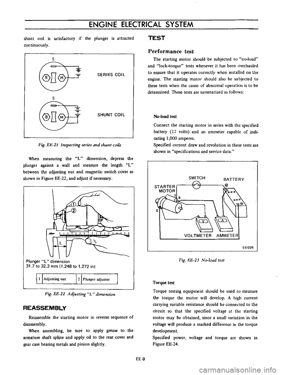
When
measuring
the
L
dimension
depress
the
plunger
against
a
wall
and
measure
the
length
L
between
the
adjusting
nut
and
magnetic
switch
cover
as
shown
in
Figure
EE
22
and
adjust
if
necessary
II
L
T
Plunger
L
dimension
31
7
to
32
3
mm
1
248
to
1
272
in
I
11
I
Adjusting
nut
121
Plunger
adjuster
Fig
BE
22
Adjusting
L
dimension
REASSEMBLY
Reassemble
the
starting
motor
in
reverse
sequence
of
disassembly
When
assembling
be
sure
to
apply
grease
to
the
armature
shaft
spline
and
apply
oil
to
the
rear
cover
and
gear
case
bearing
metals
and
pinion
slightly
TEST
Performance
test
The
starting
motor
should
be
subjected
to
no
load
and
lock
torque
tests
whenever
it
has
been
overhauled
to
ensure
that
it
operates
correctly
when
installed
on
the
engine
The
starting
motor
should
also
be
subjected
to
these
tests
when
the
cause
of
abnormal
operation
is
to
be
determined
These
tests
are
summarized
as
follows
No
load
test
Connect
the
starting
motor
in
series
with
the
specified
battery
12
volts
and
an
ammeter
capable
of
indi
cating
1
000
amperes
Specified
current
draw
and
revolution
in
these
tests
are
shown
in
specifications
and
service
data
STARTER
MOTOR
s
SWITCH
o
BATTERY
EtJ
VOLTMETER
AMMETER
EE026
Fig
EE
2J
No
load
test
Torque
test
Torque
testing
equipment
should
be
used
to
measure
the
torque
the
motor
will
develop
A
high
current
carrying
variable
resistance
should
be
connected
to
the
circuit
so
that
the
specified
voltage
at
the
starting
motor
may
be
obtained
since
a
small
variation
in
the
voltage
will
produce
a
marked
difference
in
the
torque
development
Specified
power
voltage
and
torque
are
shown
in
Figure
EE
24
EE
9
Page 431 of 513
ENGINE
ElECTRICAL
SYSTEM
SPECIFICATIONS
AND
SERVICE
DATA
Specifications
Manual
Automatic
Transmission
Transmission
Make
and
type
HITACHI
SI14
87M
HITACHI
S114
156
Nominal
output
KW
1
0
1
0
System
voltage
V
12
12
Weight
kg
Qb
4
6
10
1
54
11
9
No
load
Terminal
voltage
V
12
12
Current
A
less
than
60
less
than
60
Revolution
rpm
more
than
7
000
more
than
6
000
Load
Terminal
voltage
V
6
3
6
3
Current
A
less
than
420
less
than
420
Torque
kg
m
ft
Ib
more
than
0
9
6
5
more
than
1
0
7
2
Shifting
type
of
pinion
gear
Magnetic
shift
Magnetic
shift
Number
of
teeth
on
pinion
gear
9
9
Service
data
S114
87M
S114
156
Brush
length
Standard
height
mm
in
16
0
630
14
0
551
Wear
limit
mm
in
6
5
0
256
4
5
0
177
Brush
spring
tension
Standard
pressure
kg
Qb
1
6
3
5
0
8
1
8
Commutator
Outer
diameter
Standard
OD
mm
in
33
1
299
33
I
299
Wear
limit
mm
in
2
0
079
2
0
079
Difference
between
maximum
and
minimum
diameters
Repair
limit
mm
in
0
4
0
0157
0
4
0
0157
Repair
accuracy
mm
in
0
05
0
0020
0
05
0
0020
Depth
of
mica
Repair
limit
mm
in
0
2
0
0079
0
2
0
0079
Repair
accuracy
mm
in
0
5
to
0
8
0
5
to
0
8
0
0197
to
0
0315
0
0197
to
0
0315
Clearance
between
arma
ture
shaft
and
bushing
mm
in
Repair
limit
0
2
0
0079
0
2
0
0079
Vi
Repair
accuracy
mm
in
0
03
to
0
1
0
03
to
0
1
1
r
0
0012
to
0
0039
0
0012
to
0
003Q
EE
11
Page 440 of 513
ENGINE
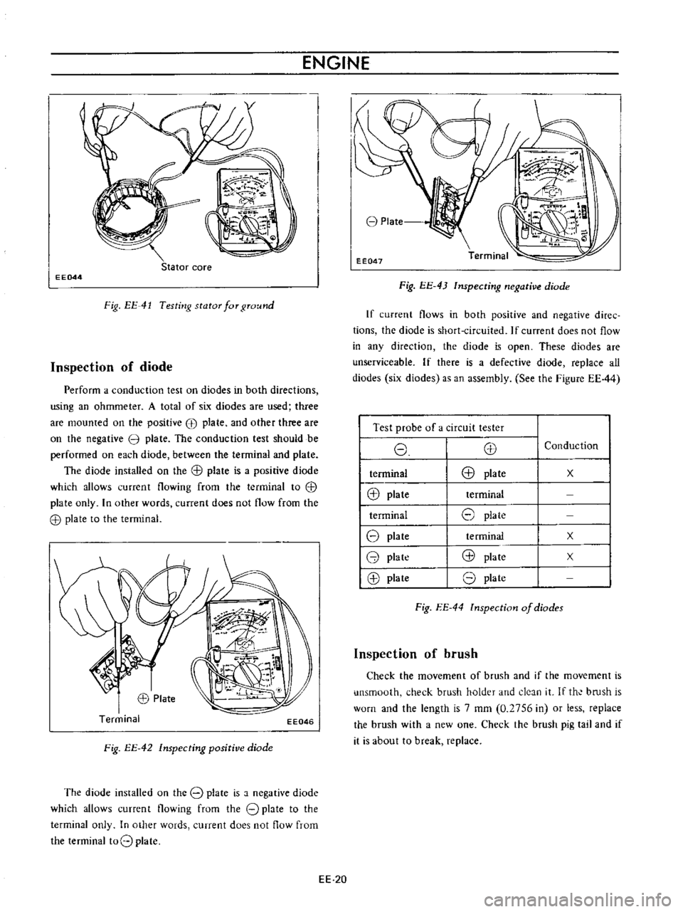
Stator
core
EE044
Fig
EE
41
Testing
stator
for
ground
Inspection
of
diode
Perform
a
conduction
test
on
diodes
in
both
directions
using
an
ohmmeter
A
total
of
six
diodes
are
used
three
are
mounted
on
the
positive
EB
plate
and
other
three
are
on
the
negative
3
plate
The
conduction
test
should
be
performed
on
each
diode
between
the
terminal
and
plate
The
diode
installed
on
the
G
l
plate
is
a
positive
diode
which
allows
current
flowing
from
the
terminal
to
G
l
plate
only
In
other
words
current
does
not
flow
from
the
G
l
plate
to
the
terminal
EE046
Fig
EE
42
Inspecting
positive
diode
The
diode
installed
on
the
8
plate
is
a
negative
diode
which
allows
current
flowing
from
the
8
plate
to
the
terminal
only
In
other
words
current
does
not
flow
from
the
terminal
t08
plate
EE
20
8
Plate
EE047
Fig
EE
43
Inspecting
negative
diode
If
current
flows
in
both
positive
and
negative
diree
tions
the
diode
is
short
circuited
If
current
does
not
flow
in
any
direction
the
diode
is
open
These
diodes
are
unserviceable
If
there
is
a
defective
diode
replace
all
diodes
six
diodes
as
an
assembly
See
the
Figure
EE44
I
Test
probe
of
a
circuit
tester
I
8
E8
I
terminal
E8
plate
I
@
plate
terminal
I
terminal
8
plate
18
plate
te
rminal
18
plate
@
plate
18
plate
8
plate
Conduction
x
x
x
Fig
EE
44
lnspection
of
diodes
Inspection
of
brush
Check
the
movement
of
brush
and
if
the
movement
is
unsmooth
check
brush
holder
and
deJn
it
If
th
bmsh
is
worn
and
the
length
is
7
mm
0
2756
in
or
less
replace
the
brush
with
a
new
one
Check
the
brush
pig
tail
and
if
it
is
about
to
break
replace
Page 442 of 513
ENGINE
terminal
to
IN
terminal
or
BAT
terminal
Connect
the
other
test
probe
to
ground
Make
sure
that
voltmeter
registers
battery
voltage
4
Start
the
engine
3
Turn
on
the
headlights
and
switch
to
main
beam
I
o
B
ttefY
E
A
J
0
il
I
5
Increase
engine
speed
gradually
until
it
is
approxi
mately
1
100
rpm
and
take
the
voltmeter
reading
6
If
the
measured
value
is
over
12
5
volts
the
alternator
is
in
good
condition
o
I
eE052
Voltmeter
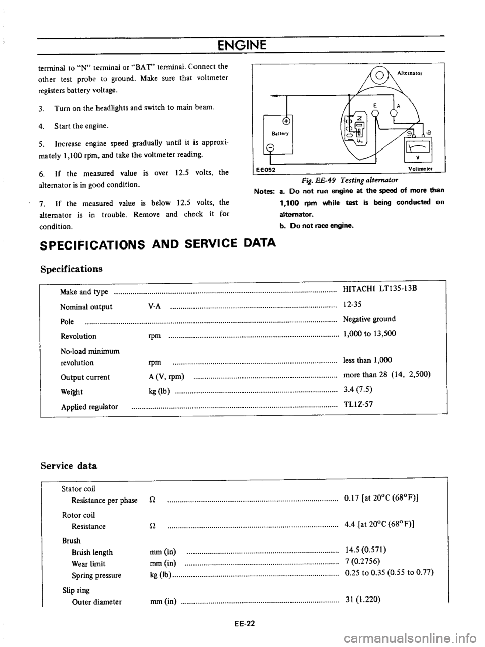
Fig
EE
49
Testing
altematoT
Notes
8
Do
not
run
engine
at
the
speed
of
more
than
1
100
rpm
while
test
is
being
conducted
on
alternator
b
Do
not
race
engine
7
If
the
measured
value
is
below
12
5
volts
the
alternator
is
in
trouble
Remove
and
check
it
for
condition
SPECIFICATIONS
AND
SERVICE
DATA
Specifications
Make
and
type
Nominal
output
Pole
Revolution
No
load
minimum
revolution
Output
current
Wei
t
Applied
regulator
Service
data
Stator
coil
Resistance
per
phase
Rotor
coil
Resistance
Brush
Brush
length
Wear
limit
Spring
pressure
Slip
ring
Outer
diameter
V
A
HITACHI
LTl35
13B
12
35
rpm
Negative
ground
1
000
to
13
500
rpm
A
V
rpm
kg
1b
less
than
1
000
more
than
28
14
2
500
3
4
7
5
TLl
Z
57
n
0
17
at
200C
680F
n
4
4
at
200e
680
F
mm
in
mm
in
kg
lb
14
5
0
571
7
0
2756
0
25
to
0
35
0
55
to
0
77
mm
in
31
1
220
EE
22
Page 459 of 513

ENGINE
ELECTRICAL
SYSTEM
TROUBLE
DIAGNOSES
AND
CORRECTIONS
When
engine
does
not
start
If
there
is
no
trouble
in
fuel
system
ignition
system
should
be
checked
This
can
be
easily
done
by
detaching
a
high
tension
cable
from
spark
plug
starting
engine
and
observing
condition
of
spark
that
occurs
between
high
tension
cable
and
spark
plug
terminal
After
checking
this
repair
as
necessary
Length
of
Trouble
location
Cause
Remedies
spark
gap
No
sparks
at
all
Distributor
Defective
insulation
of
condenser
Replace
Breakage
of
lead
wire
on
low
tension
side
Repair
Defective
insulation
of
cap
and
rotor
head
Replace
Point
does
not
open
or
close
Repair
Ignition
coil
Wire
breakage
or
short
circuit
of
coil
Replace
with
new
one
High
tension
cable
Wire
coming
off
Repair
Defective
insulation
Replace
I
to
2
mm
0
0394
Distributor
Point
gap
too
wide
Correct
to
0
0787
in
or
Oil
sticking
on
point
Clean
irregular
Point
burnt
too
much
Replace
Less
than
6
mm
Spark
plugs
Electrode
gap
too
wide
Correct
or
replace
0
2362
in
Too
much
carbon
Clean
or
replace
Broken
neck
of
insulator
Replace
Expiry
of
plug
life
Replace
2
When
engine
rotates
but
does
not
run
smoothly
In
this
case
there
are
many
causes
resulting
from
the
ignition
system
and
other
engine
conditions
not
related
to
ignition
Therefore
first
complete
inspection
of
ignition
system
should
be
carried
out
EE
39
Page 480 of 513
CHASSIS
2
Apply
brake
fluid
sufficiently
to
the
cylinder
and
piston
and
assemble
them
Reinstallation
Reinstall
the
master
cylinder
assembly
in
reverse
sequence
of
removal
and
adjust
as
follows
I
Adjust
the
pedal
height
by
changing
the
push
rod
length
2
B
eed
air
out
of
the
hydraulic
system
OPERATING
CYLINDER
Hydraulic
clutch
Removal
Remove
the
return
spring
2
Disconnect
the
clutch
line
from
the
operating
cyl
inder
3
Disconnect
the
push
rod
from
the
withdrawal
lever
4
Release
two
bolts
used
to
mount
the
operating
cylinder
to
the
clutch
housing
Disassembly
1
Remove
the
dust
cover
2
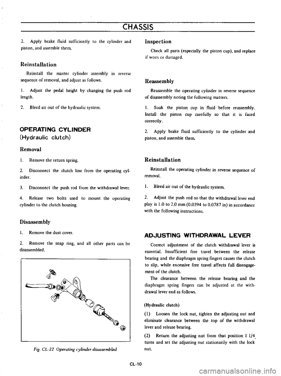
Remove
the
snap
ring
and
all
other
parts
can
be
disassembled
@
Fig
CL
22
Operating
cylinder
disassembled
CL
10
Inspection
Check
all
parts
especially
the
piston
cup
and
replace
if
worn
or
damaged
Reassembly
Reassemble
the
operating
cylinder
in
reverse
sequence
of
disassembly
noting
the
following
matters
Soak
the
piston
cup
in
fluid
before
reassembly
Install
the
piston
cup
carefully
so
that
it
is
faced
correctly
2
Apply
brake
fluid
sufficiently
to
the
cylinder
and
piston
and
assemble
them
Reinstallation
Reinstal
the
operating
cylinder
in
reverse
sequence
of
removal
1
Bleed
air
out
of
the
hydraulic
system
2
Adjust
the
push
rod
so
that
the
withdrawal
lever
end
play
is
0
to
2
0
mm
0
0394
to
0
0787
in
in
accordance
with
the
following
instructions
AD
USTING
WITHDRAWAL
LEVER
Correct
adjustment
of
the
clutch
withdrawal
lever
is
essential
Insufficient
free
travel
between
the
release
bearing
and
the
diaphragm
spring
fingers
causes
the
clutch
to
slip
while
excessive
free
travel
affects
full
disengage
ment
of
the
clutch
The
clearance
between
the
release
bearing
and
the
diaphragm
spring
fingers
can
be
adjusted
at
the
with
drawallever
end
as
follows
Hydraulic
clutch
Loosen
the
lock
nut
tighten
the
adjusting
nut
and
eliminate
clearance
between
the
top
of
the
withdrawal
lever
and
release
bearing
2
Return
the
adjusting
nut
from
that
position
I
4
turns
and
set
the
adjusting
nut
stationarily
with
the
lock
nut