1973 DATSUN B110 length
[x] Cancel search: lengthPage 177 of 513
STEERING
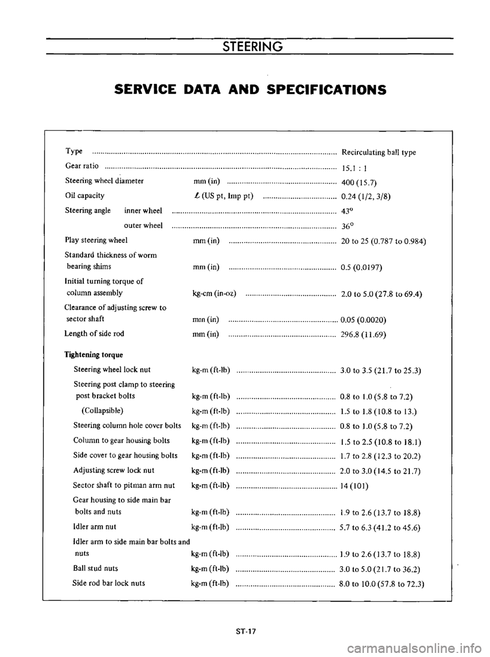
SERVICE
DATA
AND
SPECIFICATIONS
Type
Gear
ratio
Steering
wheel
diameter
Oil
capacity
Steering
angle
inner
wheel
outer
wheel
Play
steering
wheel
Standard
thickness
of
worrn
bearing
shims
Initial
turning
torque
of
column
assembly
Clearance
of
adjusting
screw
to
sector
shaft
Length
of
side
rod
Tightening
torque
Steering
wheel
lock
nut
Steering
post
clamp
to
steering
post
bracket
bolls
Collapsible
Steering
column
hole
cover
bolts
Column
to
gear
housing
bolts
Side
cover
to
gear
housing
bolts
Adjusting
screw
lock
nut
Sector
shaft
to
pitman
arm
nut
Gear
housing
to
side
main
bar
bolts
and
nuts
Idler
arm
nut
Recirculating
ball
type
mm
in
L
US
pt
Imp
pt
15
I
I
400
157
0
24
I
2
3
8
430
360
mm
in
20
to
25
0
787
to
0
984
mm
in
0
5
0
0197
kg
em
in
oz
2
0
to
5
0
27
8
to
69
4
mrn
in
mm
in
0
05
0
0020
296
8
11
69
kg
m
ft
lb
3
0
to
3
5
217
to
25
3
kg
m
ft
lb
kg
m
ft
Ib
kg
m
ft
lb
kg
m
ft
lb
kg
m
ft
lb
kg
m
ft
lb
kg
m
ft
lb
0
8
to
1
0
5
8
to
7
2
1
5
to
1
8
10
8
to
13
0
8
to
1
0
5
8
to
7
2
1
5
to
2
5
10
8
to
18
1
I
7
to
2
8
12
3
to
20
2
2
0
to
3
0
14
5
to
21
7
14
101
kg
m
ft
lb
kg
m
ft
lb
1
9
to
2
6
13
7
to
18
8
57
to
6
3
41
2
to
45
6
Idler
arm
to
side
main
bar
bolts
and
nuts
kg
m
ft
Ib
Ball
stud
nuts
kg
m
ft
lb
Side
rod
bar
lock
nuts
kg
m
ft
lb
1
9
to
2
6
13
7
to
18
8
3
0
to
5
0
21
7
to
36
2
8
0
to
10
0
57
8
to
72
3
ST
17
Page 205 of 513
BODY
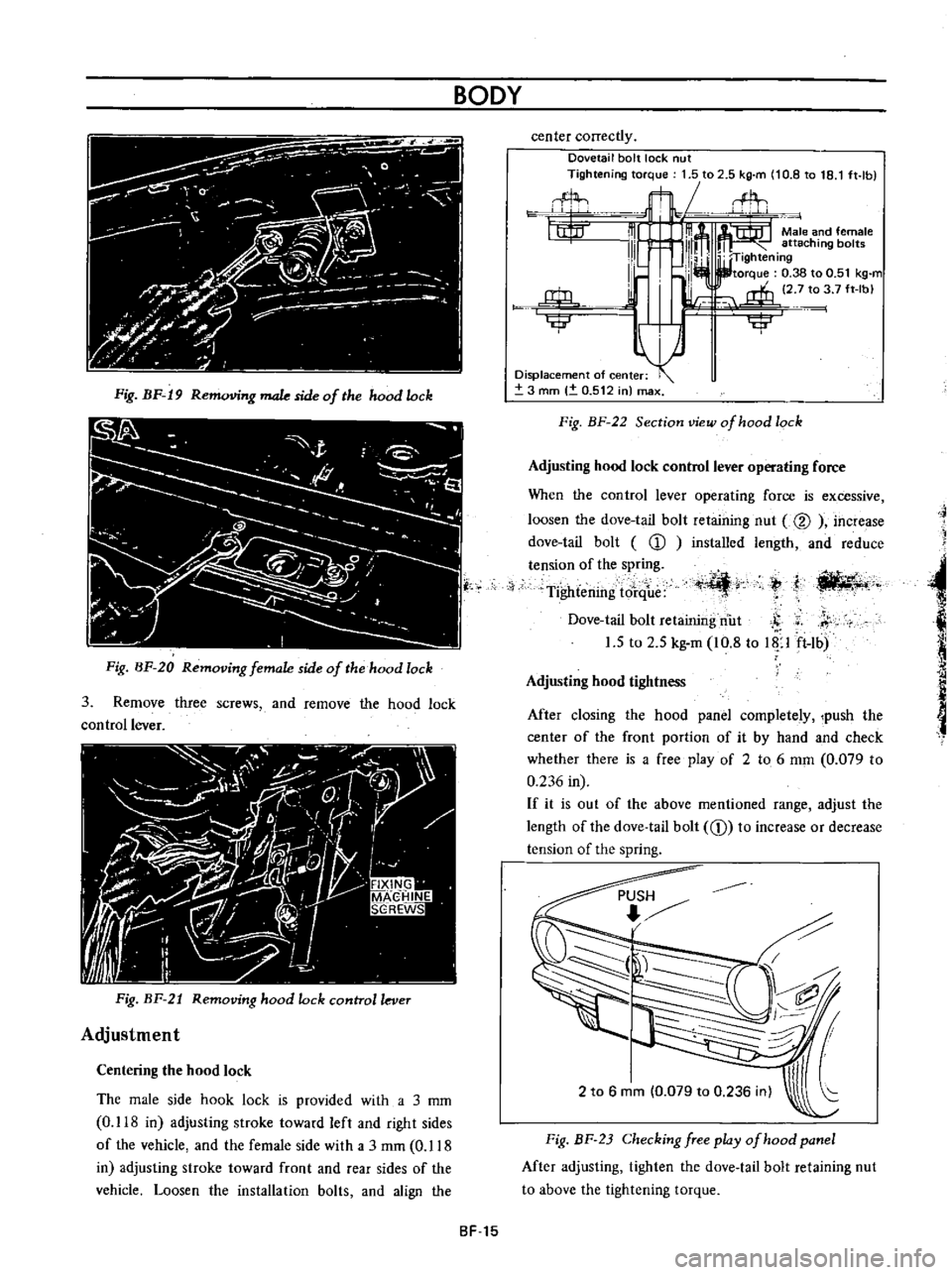
Fig
BF
19
R
g
male
side
of
the
hood
lock
Fig
BF
20
Removing
female
side
of
the
hood
lock
3
Remove
three
screws
and
remove
the
hood
lock
control
lever
Fig
BF
21
Removing
hood
lock
control
lever
Adjustment
Centering
the
hood
lock
The
male
side
hook
lock
is
provided
with
a
3
mm
0
118
in
adjusting
stroke
toward
left
and
right
sides
of
the
vehicle
and
the
female
side
with
a
3
rnm
0
118
in
adjusting
stroke
toward
front
and
rear
sides
of
the
vehicle
Loosen
the
installation
bolts
and
align
the
center
correctly
Dovetail
bolt
lock
nut
Tightening
torque
1
5
to
2
5
kg
m
10
8
to
18
1
ft
lb
flL
t1t
m
m
Male
and
female
111
l
111m
attaching
bol
W
TIghtening
I
lb
I
I
torque
0
38
to
0
51
kg
m
l
i
2
7
to
3
7
ft
Ibl
j
rffi
u
Ilillr
iji
Displacement
of
center
3
mm
0
512
in
max
Fig
BF
22
Section
view
of
hood
lock
Adjusting
hood
lock
control
lever
operating
force
When
the
control
lever
operating
force
is
excessive
loosen
the
dove
tail
bolt
retaining
nut
@
increase
dove
tail
bolt
CD
installed
length
and
reduce
tension
of
the
spring
Tightening
tore
ue
t
I
ili
4r
ti
llt4
t
j
Dove
tail
bolt
retaining
nut
S
r
1
5
to
2
5
kg
m
10
8
to
Up
ft
lb
Adjusting
hood
tightness
After
closing
the
hood
panel
completely
push
the
center
of
the
front
portion
of
it
by
hand
and
check
whether
there
is
a
free
play
of
2
to
6
mm
0
079
to
0
236
in
If
it
is
out
of
the
above
mentioned
range
adjust
the
length
of
the
dove
tail
bolt
CD
to
increase
or
decrease
tension
of
the
spring
2
to
6
mm
0
079
to
0
236
inl
Fig
BF
23
Checking
free
play
of
hood
panel
After
adjusting
tighten
the
dove
tail
bolt
retaining
nut
to
above
the
tightening
torque
SF
15
Page 241 of 513
INSPECTION
Referring
to
the
wiring
diagram
check
the
wiring
harness
for
connection
with
electrical
equipment
and
connector
for
conned
ion
and
installation
When
checking
the
wiring
harness
note
the
following
matters
Connected
unit
should
not
be
loose
rusted
or
contaminated
2
Cable
insulator
cover
should
not
be
damaged
crack
ed
or
insulating
material
should
not
be
deteriorated
3
For
those
parts
which
are
grounded
through
the
installation
bolts
the
bolts
should
be
in
contact
with
the
body
completely
so
that
continuity
is
provided
in
between
the
body
and
bolts
4
Terminals
of
unit
through
which
current
flows
should
not
come
into
contact
with
other
metal
parts
5
No
erroneous
connection
should
be
present
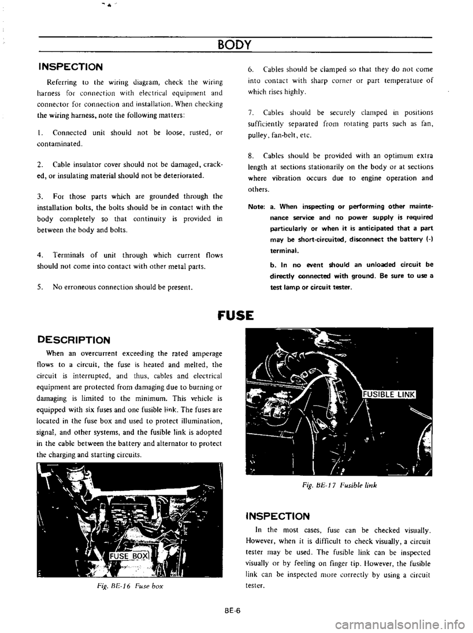
DESCRIPTION
When
an
overcunent
exceeding
the
rated
amperage
flows
to
a
circuit
the
fuse
is
heated
and
melted
the
circuit
is
interrupted
and
thus
cables
and
electrical
equipment
are
protected
from
damaging
due
to
burning
or
damaging
is
limited
to
the
minimum
This
vehicle
is
equipped
with
six
fuses
and
one
fusible
link
The
fuses
are
located
in
the
fuse
box
and
used
to
protect
illumination
signal
and
other
systems
and
the
fusible
link
is
adopted
in
the
cable
between
the
battery
and
alternator
to
protect
the
charging
and
starting
circuits
FiJ
BE
16
Fuse
box
BODY
6
Cables
should
be
damped
so
that
they
do
not
come
into
contact
with
sharp
corner
or
part
lernperature
of
which
rises
highly
7
Cables
should
be
securely
clamped
in
posItions
sufficiently
separated
from
rotating
parts
such
as
fan
pulley
fan
belt
etc
8
Cables
should
be
provided
with
an
optimum
extra
length
at
sections
stationarity
on
the
body
or
at
sections
where
vibration
occurs
due
to
engine
operation
and
others
Note
a
When
inspecting
or
performing
other
mainte
nance
service
and
no
power
supply
is
required
particularly
or
when
it
is
anticipated
that
a
part
may
be
short
circuited
disconnect
the
battery
H
terminal
b
In
no
event
should
an
unloaded
circuit
be
directly
connected
with
ground
Be
sure
to
use
a
test
lamp
or
circuit
tester
fUSE
Fig
BE
17
Fusible
link
INSPECTION
In
the
most
cases
fuse
can
be
checked
visually
However
when
it
is
difficult
to
check
visually
a
circuit
tester
may
be
used
The
fusible
link
can
be
inspected
visually
or
by
feeling
on
finger
tip
However
the
fusible
link
can
be
inspected
more
correctly
by
using
a
circuit
tester
BE
6
Page 326 of 513
EMISSION
CONTROL
AND
TUNE
UP
Appearance
1
First
inspect
whether
vacuum
hoses
are
connected
to
correct
positions
2
Inspect
hoses
for
cracks
distortion
or
plugging
Checking
of
vacuum
motor
I
With
engine
shut
down
inspect
the
position
of
valve
placing
a
mirror
at
the
end
of
inlet
pipe
for
inspec
tion
The
correct
condition
of
valve
is
that
it
keeps
the
inlet
of
underhood
air
open
and
that
of
hot
air
closed
Otherwise
inspect
the
linkage
of
valve
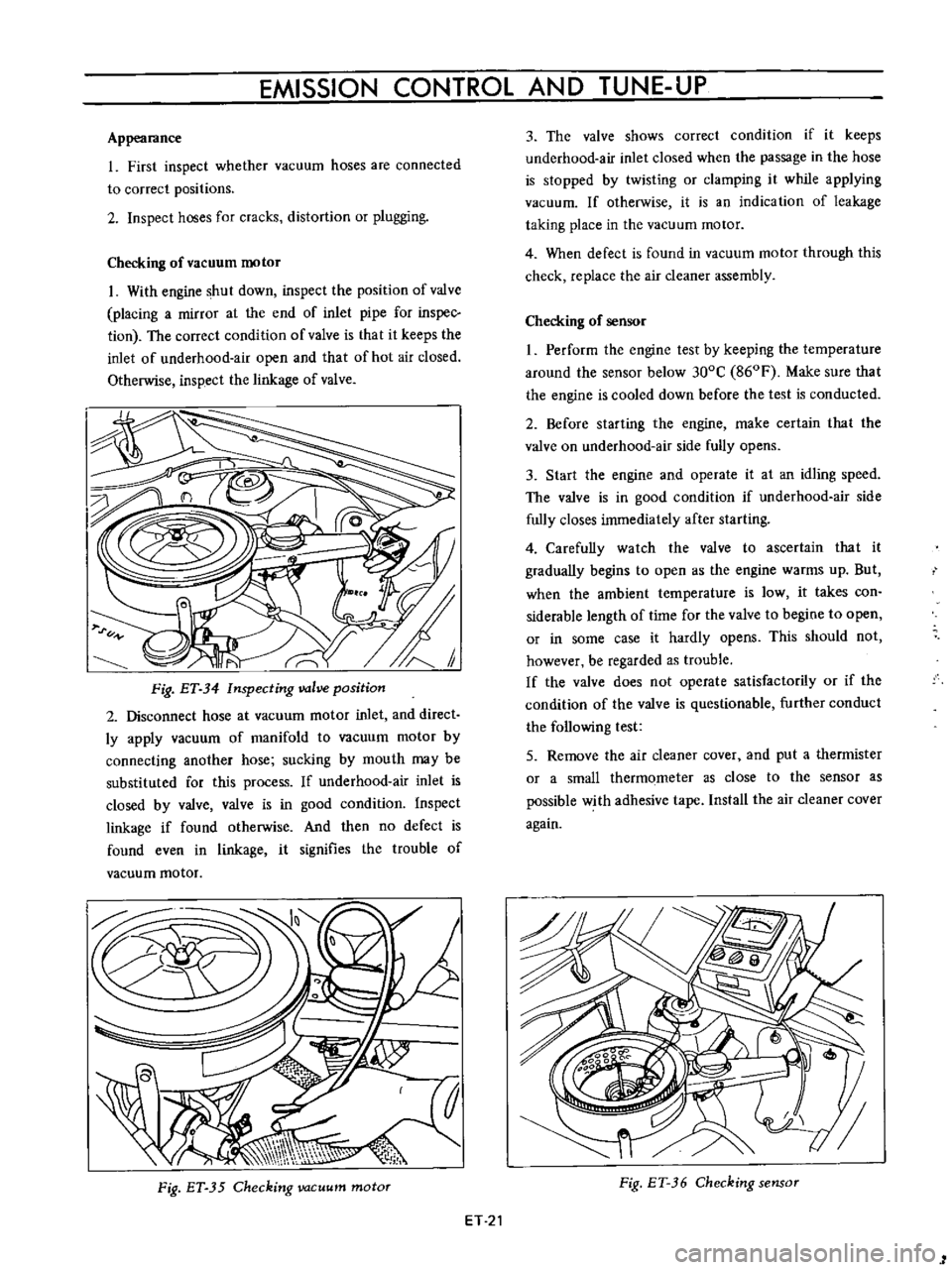
Fig
ET
34
Inspecting
valve
position
2
Disconnect
hose
at
vacuum
motor
inlet
and
direct
ly
apply
vacuum
of
manifold
to
vacuum
motor
by
connecting
another
hose
sucking
by
mouth
may
be
substituted
for
this
process
If
underhood
air
inlet
is
closed
by
valve
valve
is
in
good
condition
Inspect
linkage
if
found
otherwise
And
then
no
defect
is
found
even
in
linkage
it
signifies
the
trouble
of
vacuum
motor
Fig
ET
35
Checking
vacuum
motor
ET
21
3
The
valve
shows
correct
condition
if
it
keeps
underhood
air
inlet
closed
when
the
passage
in
the
hose
is
stopped
by
twisting
or
clamping
it
while
applying
vacuum
If
otherwise
it
is
an
indication
of
leakage
taking
place
in
the
vacuum
motor
4
When
defect
is
found
in
vacuum
motor
through
this
check
replace
the
air
cleaner
assembly
Checking
of
sensor
I
Perform
the
engine
test
by
keeping
the
temperature
around
the
sensor
below
300C
860F
Make
sure
that
the
engine
is
cooled
down
before
the
test
is
conducted
2
Before
starting
the
engine
make
certain
that
the
valve
on
underhood
air
side
fully
opens
3
Start
the
engine
and
operate
it
at
an
idling
speed
The
valve
is
in
good
condition
if
underhood
air
side
fully
closes
immediately
after
starting
4
Carefully
watch
the
valve
to
ascertain
that
it
gradually
begins
to
open
as
the
engine
warms
up
But
when
the
ambient
temperature
is
low
it
takes
con
siderable
length
of
time
for
the
valve
to
begine
to
open
or
in
some
case
it
hardly
opens
This
should
not
however
be
regarded
as
trouble
If
the
valve
does
not
operate
satisfactorily
or
if
the
condition
of
the
valve
is
questionable
further
conduct
the
following
test
5
Remove
the
air
cleaner
cover
and
put
a
thermister
or
a
small
thermometer
as
close
to
the
sensor
as
possible
with
adhesive
tape
Install
the
air
cleaner
cover
again
Fig
ET
36
Checking
sensor
1
Page 350 of 513
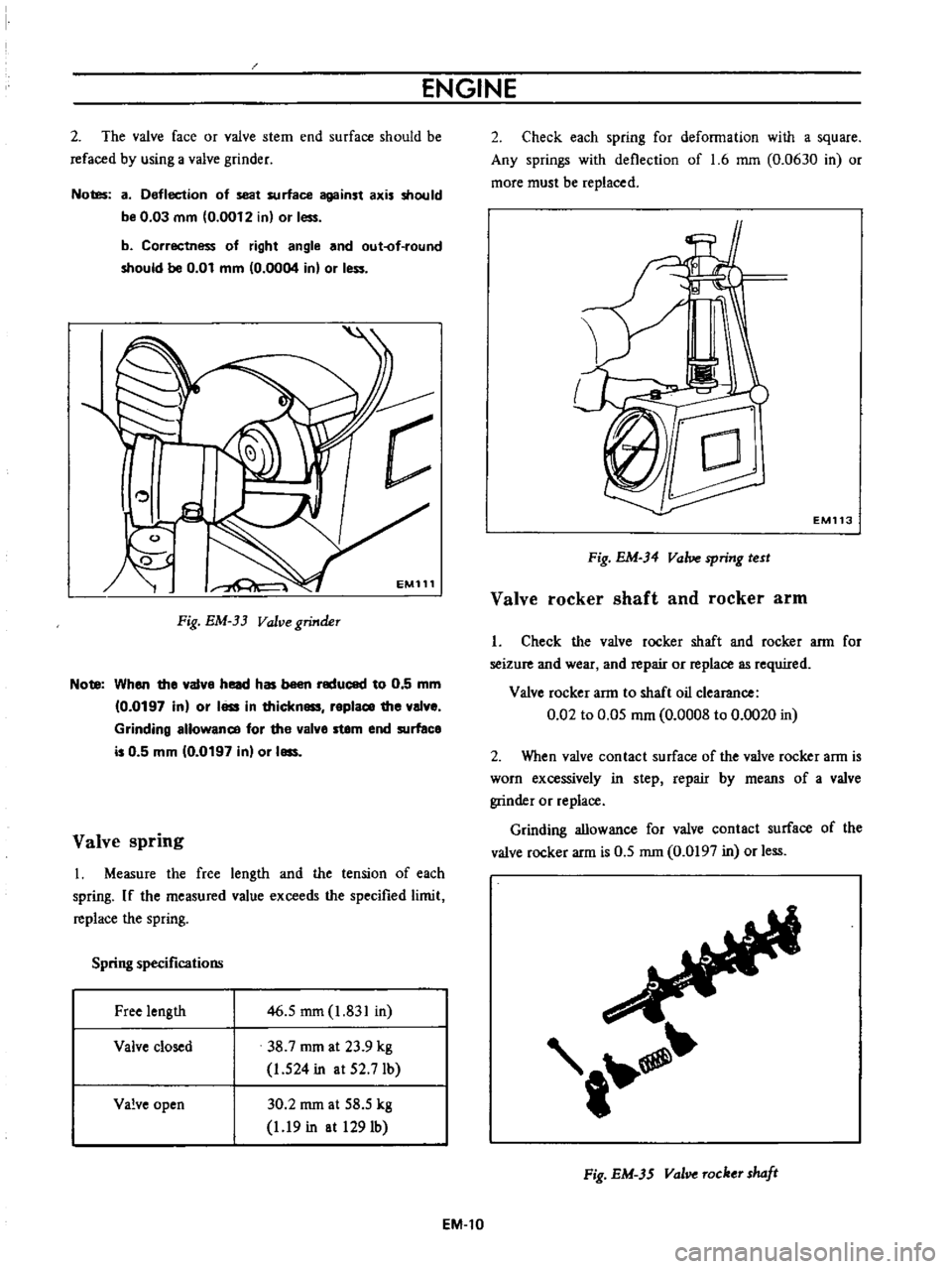
ENGINE
2
The
valve
face
or
valve
stem
end
surface
should
be
refaced
by
using
a
valve
grinder
Notes
a
Deflection
of
seat
surface
against
axis
should
be
0
03
mm
0
0012
in
or
less
b
Correctness
of
right
angle
and
out
of
round
should
be
0
01
mm
0
0004
in
or
I
c
EM111
Fig
EM
33
Valve
grinder
Note
When
the
a1ve
head
has
been
reduced
to
0
5
mm
0
0197
in
or
I
in
thickn
replace
the
al
e
Grinding
allowance
for
the
alve
stem
end
surface
is
0
5
mm
10
0197
in
or
I
Valve
spring
I
Measure
the
free
length
and
the
tension
of
each
spring
If
the
measured
value
exceeds
the
specified
limit
replace
the
spring
Spring
specifications
Free
length
46
5
mm
1
831
in
38
7
rom
at
23
9
kg
1
524
in
at
52
7Ib
Valve
closed
Valve
open
30
2
rom
at
58
5
kg
1
19
in
at
1291b
EM
l0
2
Check
each
spring
for
deformation
with
a
square
Any
springs
with
deflection
of
1
6
mm
0
0630
in
or
more
must
be
replaced
EM113
Fig
EM
34
Valve
spring
test
Valve
rocker
shaft
and
rocker
arm
I
Check
the
valve
rocker
shaft
and
rocker
arm
for
seizure
and
wear
and
repair
or
replace
as
required
Valve
rocker
arm
to
shaft
oil
clearance
0
02
to
0
05
mm
0
0008
to
0
0020
in
2
When
valve
contact
surface
of
the
valve
rocker
arm
is
worn
excessively
in
step
repair
by
means
of
a
valve
grinder
or
replace
Grinding
allowance
for
valve
contact
surface
of
the
valve
rocker
arm
is
0
5
rom
0
0197
in
or
less
t
Fig
EM
3S
val
Tocker
shaft
Page 359 of 513
ENGINE
MECHANICAL
Note
8
When
the
piston
ring
only
is
to
be
replaced
without
the
cylinder
bore
being
corrected
measure
gap
at
the
bottom
of
the
cylinder
where
the
wear
is
minor
b
Oversize
piston
rings
are
available
for
service
50
100
150
oversize
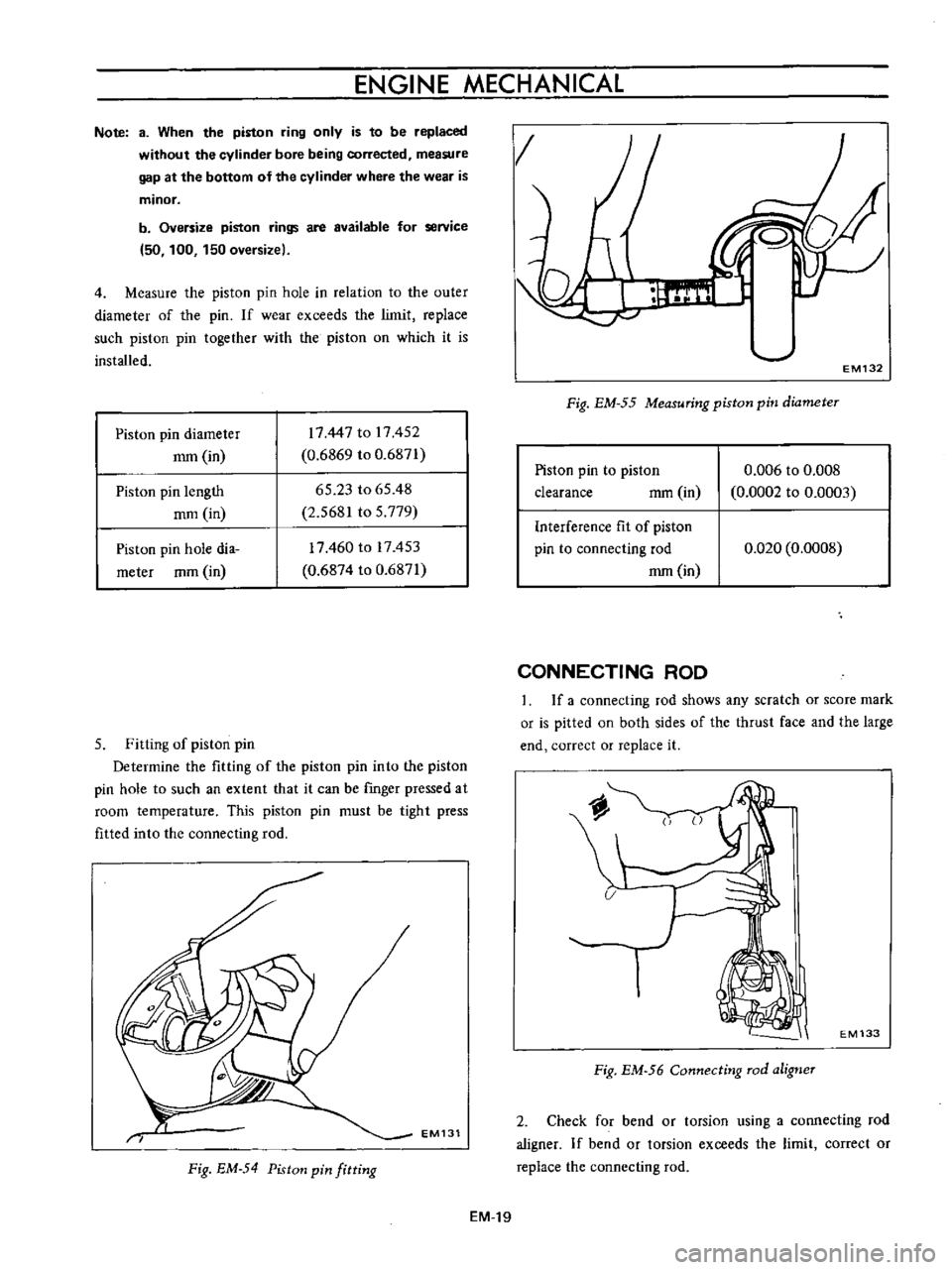
4
Measure
the
piston
pin
hole
in
relation
to
the
outer
diameter
of
the
pin
If
wear
exceeds
the
limit
replace
such
piston
pin
together
with
the
piston
on
which
it
is
installed
Piston
pin
diameter
mm
in
17447
to
17452
0
6869
to
0
6871
65
23
to
65
48
2
5681
to
5
779
Piston
pin
length
mm
in
Piston
pin
hole
dia
meter
mm
in
17460
to
17453
0
6874
to
0
6871
5
Fitting
of
piston
pin
Determine
the
fitting
of
the
piston
pin
into
the
piston
pin
hole
to
such
an
extent
that
it
can
be
rmger
pressed
at
room
temperature
This
piston
pin
must
be
tight
press
fitted
into
the
connecting
rod
EM131
Fig
EM
54
Piston
pin
fitting
EM
19
g
1
EM132
Fig
EM
55
Measuring
piston
pin
diameter
Piston
pin
to
piston
clearance
mm
in
0
006
to
0
008
0
0002
to
0
0003
Interference
fit
of
piston
pin
to
connecting
rod
mm
in
0
020
0
0008
CONNECTING
ROD
If
a
connecting
rod
shows
any
scratch
or
score
mark
or
is
pitted
on
both
sides
of
the
thrust
face
and
the
large
end
correct
or
replace
it
EM133
Fig
EM
56
Connecting
rod
aligner
2
Check
for
bend
or
torsion
using
a
connecting
rod
aligner
If
bend
or
torsion
exceeds
the
limit
correct
or
replace
the
connecting
rod
Page 360 of 513
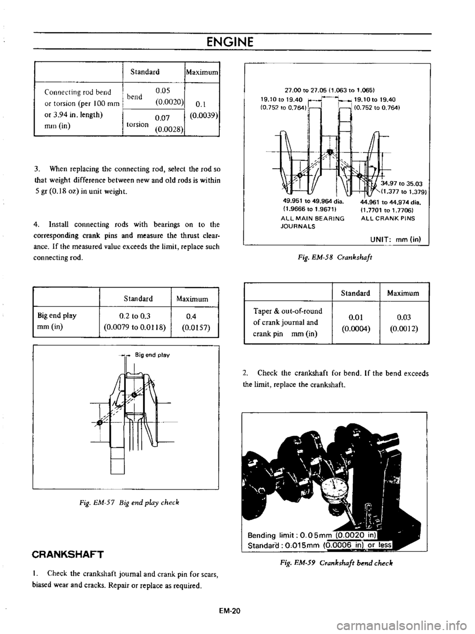
ENGINE
Standard
IMaXimum
Connecting
rod
bend
or
torsion
per
100
mm
or
3
94
in
length
mm
in
o
os
0
0020
0
07
0
0028
0
1
0
0039
bend
torsion
3
When
replacing
the
connecting
rod
select
the
rod
so
that
weight
difference
between
new
and
old
rods
is
within
S
gr
0
18
oz
in
unit
weight
4
Install
connecting
rods
with
bearings
on
to
the
corresponding
crank
pins
and
measure
the
thrust
clear
ance
If
the
measured
value
exceeds
the
limit
replace
such
connecting
rod
Stan
dard
Maximum
Big
end
play
mm
in
0
2
to
0
3
0
0079
to
0
Ql18
0
4
0
0IS7
l
8ig
end
plav
A
t
f
L
Fig
EM
57
Big
end
play
check
CRANKSHAFT
Check
the
crankshaft
journal
and
crank
pin
for
scars
biased
wear
and
cracks
Repair
or
replace
as
required
EM
20
27
00
to
27
05
1
063
to
1
065
19
1Ot01940
r
19
10t019
40
fO
752
to
0
764
Ii
10
75Z
to
0
764
I
c
1
r
1tf
1
I
J
X
I
34
97
to
35
03
t
11
377
to
1
379
49
951
to
49
964
dia
11
9666
to
1
96711
ALL
MAIN
BEARING
JOURNALS
Fig
EM
58
Crankshaft
Standard
Taper
out
of
round
of
crank
journal
and
crank
pin
mm
in
0
01
0
0004
44
961
to
44
974
die
11
7701
to
1
7706
ALL
CRANK
PINS
UNIT
ffim
in
Maximum
0
03
0
0012
2
Check
the
crankshaft
for
bend
If
the
bend
exceeds
the
limit
replace
the
crankshaft
Bending
limit
0
05mm
0
0020
in
Standaia
0
015mm
0
0006
in
or
less
Fig
EM
59
Crankshaft
bend
check
Page 374 of 513
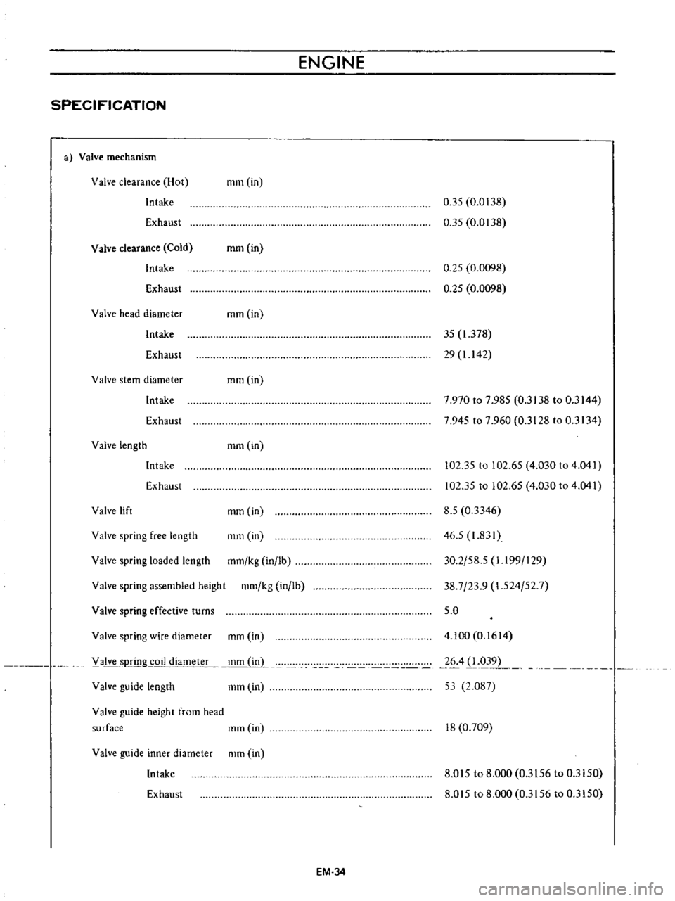
ENGINE
SPECIFICATION
a
Valve
mechanism
Valve
clearance
Hot
Intake
mm
in
Exhaust
0
35
0
0138
0
35
0
0138
Valve
clearance
Cold
Intake
Exhaust
mm
in
0
25
0
0098
0
25
0
0098
Valve
head
diameter
mm
in
Intake
35
1
378
29
1
142
Exhaust
Valve
stem
diameter
mm
in
Intake
7
970
to
7
985
0
3138
to
0
3144
7
945
to
7
960
0
3128
to
0
3134
Exhaust
Valve
length
mm
in
Intake
Exhaust
102
35
to
102
65
4
030
to
4
041
102
35
to
102
65
4
030
to
4
041
Valve
spring
assembled
height
111m
kg
in
lb
8
5
0
3346
46
5
1
831
30
2
58
5
1
I99
129
38
7
23
9
1
524
52
7
5
0
Valve
lift
mm
in
Valve
spring
free
length
mm
in
Valve
spring
loaded
length
mm
kg
in
lb
Valve
spring
effective
turns
Valve
guide
length
111m
in
4
100
0
1614
26
4
1
031
1
53
2
087
Valve
spring
wire
diameter
mm
in
V
alve
sp
g
coil
diameter
inm
L
Valve
guide
height
from
head
surface
111m
in
18
0
709
Valve
guide
inner
diameter
mm
in
Intake
8
015
to
8
000
0
3156
to
0
3150
Exhaust
8
015
to
8
000
0
3156
to
0
3150
EM
34