Page 399 of 513

ENGINE
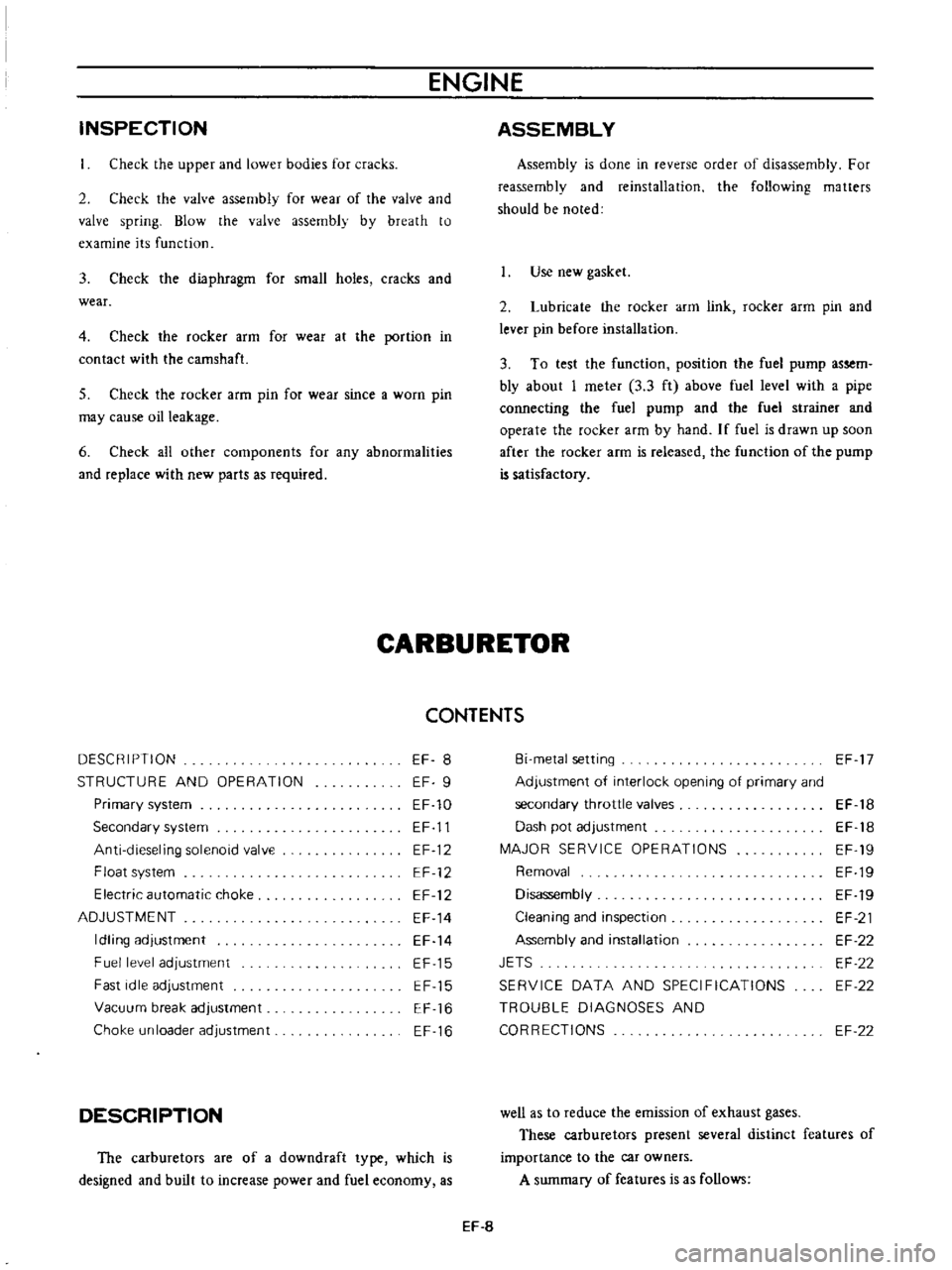
INSPECTION
Check
the
upper
and
lower
bodies
for
cracks
2
Check
the
valve
assembly
for
wear
of
the
valve
and
valve
spring
Blow
the
valve
assembly
by
breath
to
examine
its
function
3
Check
the
diaphragm
for
small
holes
cracks
and
wear
4
Check
the
rocker
arm
for
wear
at
the
portion
in
contact
with
the
camshaft
5
Check
the
rocker
arm
pin
for
wear
since
a
worn
pin
may
cause
oil
leakage
6
Check
all
other
components
for
any
abnormalities
and
replace
with
new
parts
as
required
ASSEMBLY
Assembly
is
done
in
reverse
order
of
disassembly
For
reassembly
and
reinstallation
the
following
matters
should
be
noted
Use
new
gasket
2
Lubricate
the
rocker
arm
link
rocker
arm
pin
and
lever
pin
before
installation
3
To
test
the
function
position
the
fuel
pump
assem
bly
about
I
meter
3
3
ft
above
fuel
level
with
a
pipe
connecting
the
fuel
pump
and
the
fuel
strainer
and
operate
the
rocker
afm
by
hand
If
fuel
is
drawn
up
soon
after
the
rocker
arm
is
released
the
function
of
the
pump
is
satisfactory
CARBURETOR
CONTENTS
DESCRIPTION
STRUCTURE
AND
OPERATION
EF
8
EF
9
EF
10
EF
11
EF
12
EF
12
EF
12
EF
14
EF
14
EF
15
EF
15
EF
16
EF
16
Primary
system
Secondary
system
Anti
dieseling
solenoid
valve
Float
system
Electric
automatic
choke
ADJUSTMENT
Idling
adjustment
Fuel
level
adjustment
Fast
idle
adjustment
Vacuum
break
adjustment
Choke
un
loader
adjustment
DESCRIPTION
The
carburetors
are
of
a
downdraft
type
which
is
designed
and
built
to
increase
power
and
fuel
economy
as
Bi
metal
setting
Adjustment
of
interlock
opening
of
primary
and
secondary
throttle
valves
Dash
pot
adjustment
MAJOR
SERVICE
OPERATIONS
Removal
Disassembly
Cleaning
and
inspection
Assembly
and
installation
JETS
SERVICE
DATA
AND
SPECIFICATIONS
TROUBLE
DIAGNOSES
AND
CORRECTIONS
EF
17
EF
18
EF
18
EF
19
EF
19
EF
19
EF
21
EF
22
EF
22
EF
22
EF
22
well
as
to
reduce
the
emission
of
exhaust
gases
These
carburetors
present
several
distinct
features
of
importance
to
the
car
owners
A
summary
of
features
is
as
follows
EF
8
Page 412 of 513

FUEL
SYSTEM
5
Check
venturi
clusters
for
loose
or
worn
parts
If
damage
or
looseness
exists
replace
cluster
assembly
6
Check
the
linkage
for
operating
condition
7
Inspect
the
operation
of
accelerating
pump
Pour
gasoline
into
the
float
chamber
and
operate
the
throttle
lever
Check
condition
of
gasoline
injection
from
the
accelerating
nozzle
Assembly
and
instalIetion
Assemble
and
install
the
carburetor
in
reverse
sequence
of
disassembly
and
removal
Replace
the
gaskets
if
necessary
When
disassembling
and
reassembling
the
interlock
link
and
related
components
be
careful
not
to
bend
or
deform
SPECIFICATIONS
AND
SERVICE
DATA
Carburetor
model
Applied
engine
Type
Outlet
diameter
mm
in
rom
in
Venturi
diameter
Main
jet
Main
air
bleed
Slow
jet
Slow
air
bleed
Power
jet
Float
level
H
rom
in
Interlock
opening
of
primary
and
secondary
throttle
valve
G
I
Throttle
valve
opening
480
mm
in
Auto
choke
Fast
idle
setting
clearance
A
mm
in
Manual
transmission
Automatic
transmission
Vacuum
break
gap
between
choke
valve
and
carburetor
body
8
mm
in
Manual
transmission
Automatic
transmission
EF
21
the
components
Reassembly
carefully
and
correctly
so
that
all
interlock
links
operate
smoothly
JETS
The
carburetor
performance
depends
on
jets
and
air
bleeds
and
the
vehicle
emissions
largely
depends
on
the
carburetor
performance
That
is
why
these
components
are
manufactured
with
utmost
care
To
clean
them
use
gasoline
and
blow
air
on
them
Changing
jet
or
air
bleed
size
may
cause
ill
vehicle
emission
So
they
should
not
be
changed
their
numbers
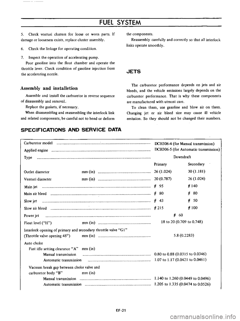
DCH3064
for
Manual
transmission
DCH306
5
for
Automatic
transmission
Downdraft
Primary
Secondary
26
1
024
30
1
181
20
0
787
26
1
024
1
95
1
140
1
80
1
80
1
43
1
50
1
215
1
100
1
60
18
to
20
0
709
to
0
748
5
8
0
2283
0
80
to
0
88
0
0315
to
0
0346
1
07
to
1
17
0
0421
to
0
0461
1
140
to
1
260
0
0449
to
0
0496
1
205
to
1
335
0
0474
to
0
0526
Page 416 of 513

FUEl
SYSTEM
EVAPORATIVE
EMISSION
CONTROL
SYSTEM
CONTENTS
OESCRI
PTION
Flow
guide
valve
MAINTENANCE
AND
TESTING
Checking
fuel
tank
vapor
liquid
separator
and
vapor
vent
I
ins
EF
25
EF
26
EF
26
EF
26
DESCRIPTION
This
system
consists
of
four
basic
elements
indicated
below
I
Fuel
tank
with
positive
sealing
filler
cap
with
relief
valve
2
Vapor
liquid
separator
3
Vapor
vent
line
4
Flow
guide
valve
The
flow
guide
valve
prevents
blow
by
gas
from
flowing
into
the
fuel
tank
and
guides
fresh
air
into
it
preventing
gasoline
vapor
from
escaping
into
the
carbure
tor
air
cleaner
Fl
me
ester
I
f
Flow
Thev
lve
opens
when
thlp
1l
rO
Inch
Hg
O
Positive
unk
venlI1atlon
PCV
hoe
Checking
fuel
tank
vacuum
relief
valve
operation
Checking
flow
guide
valve
EF
27
EF
27
Flow
guide
valve
operates
and
blow
by
gas
and
gasoline
vapor
flow
as
follows
When
the
engine
is
not
running
the
vapor
vent
line
vapor
liquid
separator
and
fuel
tank
are
filled
with
gasoline
vapor
produced
in
the
sealed
type
fuel
tank
A
flow
guide
valve
opens
when
the
gas
pressure
is
above
IOromHg
0
4
in
Hg
The
gas
passed
through
the
flow
guide
valve
2
is
accumulated
in
the
crankcase
Once
the
engine
starts
evaporates
in
the
crankcase
manifold
and
carburetor
air
cleaner
is
sucked
into
the
manifold
for
combustion
When
the
pressure
of
the
sealed
type
fuel
tank
vapor
liquid
separator
and
vapor
vent
line
becomes
negative
by
decreasing
the
fuel
the
flow
guide
valve
I
opens
to
send
fresh
air
from
the
carburetor
air
cleaner
to
the
fuel
tank
lill
K
riquidllepilrflOr
T
VilPOl
vent
line
Positiveteilling
lillercap
Fig
EF
37
Evaporative
emission
control
system
EF
25