1973 DATSUN B110 fuel pump
[x] Cancel search: fuel pumpPage 397 of 513

ENGINE
FUEL
PUMP
TESTING
A
fuel
pump
is
operating
properly
when
its
pressure
is
within
specifications
and
its
capacity
is
equal
to
the
engine
5
requirements
at
all
speeds
Pressure
and
cap
lcity
must
be
determined
by
two
tests
with
the
pump
mounted
on
the
engine
Be
sure
that
there
is
gasoline
in
the
tank
when
conducting
these
tests
Fig
EF
11
Schematic
view
of
fuel
pump
Static
pressure
test
The
static
pressure
test
is
conducted
as
follows
Disconnect
the
carburetor
fuel
line
at
the
carburetor
2
Install
the
necessary
adapter
and
tee
fitting
to
the
fuel
line
and
attach
a
suitable
pressure
gauge
Start
and
run
engine
at
varying
speeds
4
The
reading
on
the
gauge
is
the
static
fuel
pressure
and
this
should
remain
within
the
following
limits
0
18
kgJcm2
2
61b
sq
in
Pressure
below
the
lower
limit
indicates
extreme
wear
on
one
part
or
a
small
amount
of
wear
on
each
working
part
They
also
indicate
a
ruptured
diaphragm
worn
warped
dirty
or
gumming
valves
and
seats
or
weak
diaphragm
return
spring
Pressure
above
the
upper
limit
indicates
an
excessively
strong
diaphragm
that
is
too
tight
This
condition
requires
removal
of
the
fuel
pump
as
sembly
for
replacement
or
repair
Capacity
test
The
capacity
test
is
used
only
when
the
static
pressure
is
within
specifications
The
capacity
test
is
conducted
as
follows
1
Disconnect
the
fuel
pipe
at
the
carburetor
2
Place
a
suitable
container
at
the
end
of
the
pipe
3
Start
the
engine
and
run
at
1
000
rpm
4
The
pump
should
deliver
450
cc
I
V
S
p
of
fuel
in
one
minute
or
less
EF
6
Page 398 of 513

FUEL
SYSTEM
If
no
gasoline
or
only
a
little
flows
from
open
end
of
pipe
the
fuel
pipe
is
clogged
or
the
pump
is
malfunction
ing
Before
removing
the
pump
remove
the
gas
tank
cap
disconnect
both
inlet
and
outlet
pipes
and
blow
through
them
with
an
air
hose
to
make
sure
that
they
are
clear
This
will
eliminate
possible
clogged
gas
strainer
in
the
fuel
tank
Reconnect
the
pipes
to
the
pump
and
retest
flow
REMOVAL
AND
DISASSEMBLY
Remove
the
fuel
pump
assembly
by
unscrewing
two
mounting
nuts
and
disassemble
in
the
following
order
1
Separate
the
upper
body
and
the
lower
body
by
unscrewing
the
body
set
screws
2
Take
off
the
cap
and
the
cap
gasket
by
removing
the
cap
screw
3
Unscrew
the
elbow
and
the
connector
4
Take
off
the
valve
retainer
by
unscrewing
two
valve
retainer
screws
Two
valves
are
easily
removed
@
@
GS
5
To
remove
the
diaphragm
diaphragm
spring
lower
body
seal
washer
and
lower
body
seal
from
the
lower
body
press
down
the
diaphragm
counter
to
the
force
of
the
diaphragm
spring
and
while
doing
this
cant
the
diaphragm
so
that
the
rectangular
part
in
the
lower
end
of
the
pull
rod
is
unhooked
from
the
rocker
arm
link
Fig
EF
jJ
StructuTe
of
fuel
pump
EF
7
j
i
I
of
4
Fig
EF
12
Pull
Tad
Temoval
r1
r
f
i
t
1
2
3
4
5
6
7
B
9
10
tt
t2
t3
t4
15
t6
t7
tB
t9
20
2t
22
23
24
Valve
assem
bly
Packing
Retainer
Screw
Cap
Gasket
Screw
Washer
spring
Rocker
arm
Rocker
pin
Rocker
arm
spring
Spacer
Diaphragm
assembly
Retainer
Diaphragm
spring
Washer
spring
Nut
Washer
plain
Gasket
Spacer
Complete
body
lower
Connector
inlet
Connector
outlet
Page 399 of 513
ENGINE
INSPECTION
Check
the
upper
and
lower
bodies
for
cracks
2
Check
the
valve
assembly
for
wear
of
the
valve
and
valve
spring
Blow
the
valve
assembly
by
breath
to
examine
its
function
3
Check
the
diaphragm
for
small
holes
cracks
and
wear
4
Check
the
rocker
arm
for
wear
at
the
portion
in
contact
with
the
camshaft
5
Check
the
rocker
arm
pin
for
wear
since
a
worn
pin
may
cause
oil
leakage
6
Check
all
other
components
for
any
abnormalities
and
replace
with
new
parts
as
required
ASSEMBLY
Assembly
is
done
in
reverse
order
of
disassembly
For
reassembly
and
reinstallation
the
following
matters
should
be
noted
Use
new
gasket
2
Lubricate
the
rocker
arm
link
rocker
arm
pin
and
lever
pin
before
installation
3
To
test
the
function
position
the
fuel
pump
assem
bly
about
I
meter
3
3
ft
above
fuel
level
with
a
pipe
connecting
the
fuel
pump
and
the
fuel
strainer
and
operate
the
rocker
afm
by
hand
If
fuel
is
drawn
up
soon
after
the
rocker
arm
is
released
the
function
of
the
pump
is
satisfactory
CARBURETOR
CONTENTS
DESCRIPTION
STRUCTURE
AND
OPERATION
EF
8
EF
9
EF
10
EF
11
EF
12
EF
12
EF
12
EF
14
EF
14
EF
15
EF
15
EF
16
EF
16
Primary
system
Secondary
system
Anti
dieseling
solenoid
valve
Float
system
Electric
automatic
choke
ADJUSTMENT
Idling
adjustment
Fuel
level
adjustment
Fast
idle
adjustment
Vacuum
break
adjustment
Choke
un
loader
adjustment
DESCRIPTION
The
carburetors
are
of
a
downdraft
type
which
is
designed
and
built
to
increase
power
and
fuel
economy
as
Bi
metal
setting
Adjustment
of
interlock
opening
of
primary
and
secondary
throttle
valves
Dash
pot
adjustment
MAJOR
SERVICE
OPERATIONS
Removal
Disassembly
Cleaning
and
inspection
Assembly
and
installation
JETS
SERVICE
DATA
AND
SPECIFICATIONS
TROUBLE
DIAGNOSES
AND
CORRECTIONS
EF
17
EF
18
EF
18
EF
19
EF
19
EF
19
EF
21
EF
22
EF
22
EF
22
EF
22
well
as
to
reduce
the
emission
of
exhaust
gases
These
carburetors
present
several
distinct
features
of
importance
to
the
car
owners
A
summary
of
features
is
as
follows
EF
8
Page 400 of 513
FUEl
SYSTEM
Secondary
throttle
valve
is
operated
by
throttle
lever
The
high
power
and
good
acceleration
are
gained
with
combination
of
the
auxiliary
valve
2
Accelerating
pump
gives
excellent
acceleration
3
The
power
valve
mechanism
is
of
a
vacuum
actuated
boost
type
and
improves
high
speed
driving
4
The
throttle
opener
control
system
Refer
to
Section
ET
incorporates
a
servo
diaphragm
The
servo
dia
phragm
helps
open
the
throttle
valve
at
a
decreasing
speed
so
as
to
reduce
the
emission
of
hydrocarbons
to
a
minimum
5
An
anti
dieseling
solenoid
is
used
as
a
means
of
preventing
dieseling
When
the
ignition
key
is
turned
off
the
fuel
passage
involved
in
the
slow
system
is
closed
and
the
fuel
supply
is
shut
down
completely
6
In
the
choke
mechanism
an
electric
automatic
choke
is
used
to
automatically
control
the
choke
valve
operation
during
the
warm
up
of
the
engine
7
The
carburetor
for
automatic
transmission
is
equipped
with
so
called
dash
pot
that
is
it
makes
smooth
decelerating
without
engine
stall
at
any
operating
condi
tion
These
carburetors
are
quite
similar
in
appearance
as
explained
above
except
the
dash
pot
for
the
au
tomatic
transmission
model
The
differences
in
performance
are
explained
in
the
following
as
necessary
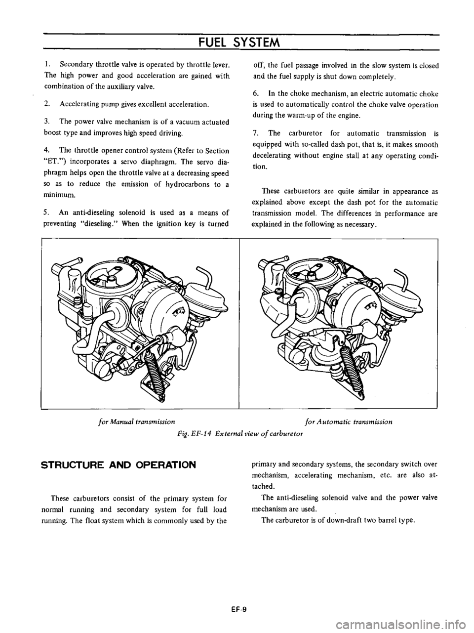
for
Manual
transmission
for
4utomatic
transmission
Fig
EF
14
External
view
of
carburetor
STRUCTURE
AND
OPERATION
These
carburetors
consist
of
the
primary
system
for
normal
running
and
secondary
system
for
full
load
running
The
float
system
which
is
commonly
used
by
the
primary
and
secondary
systems
the
secondary
switch
over
mechanism
accelerating
mechanism
etc
are
also
at
tached
The
anti
dieseling
solenoid
valve
and
the
power
valve
mechanism
are
used
The
carburetor
is
of
down
draft
two
barrel
type
EF
9
Page 402 of 513
FUEl
SYSTEM
Idling
and
slow
system
Passing
through
the
main
jet
the
fuel
passage
is
separated
from
main
line
fuel
flows
through
the
slow
jet
primary
slow
air
bleed
is
ejected
from
the
by
pass
hole
and
idle
nozzle
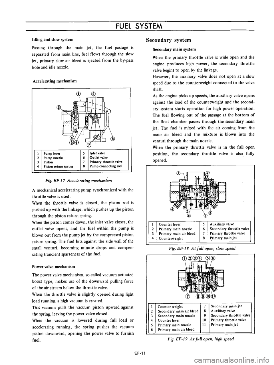
Accelerating
mechanism
Cj
f
li
Ip
j
1
2
3
4
5
Inlet
valve
6
Outlet
valve
7
Primary
throttle
valve
8
Pump
connecting
rod
Pump
lever
Pump
nozzle
Piston
Piston
return
spring
Fig
EF
17
Accelerating
mechanism
A
mechanical
accelerating
pump
synchronized
with
the
throttle
valve
is
used
When
the
throttle
valve
is
closed
the
piston
rod
is
pushed
up
with
the
linkage
which
pushes
up
the
piston
through
the
piston
return
spring
When
the
piston
comes
down
the
inlet
valve
closes
the
outlet
valve
opens
and
the
fuel
within
the
pump
is
blown
out
from
the
pump
jet
by
the
compressed
piston
return
spring
The
fuel
hits
against
the
side
wall
of
the
small
venturi
becoming
minute
drops
and
compen
sating
trancient
sparseness
of
the
fuel
Power
valve
mechanism
The
power
valve
mechanism
so
called
vacuum
actuated
boost
type
makes
use
of
the
downward
pulling
force
of
the
air
stream
below
the
throttle
valve
When
the
throttle
valve
is
slightly
opened
during
light
load
running
a
high
vacuum
is
created
This
vacuum
pulls
the
vacuum
piston
upward
against
the
spring
leaving
the
power
valve
closed
When
the
vacuum
is
lowered
during
full
load
or
accelerating
running
the
spring
pushes
the
vacuum
piston
downward
opening
the
power
valve
to
furnish
fuel
EF
11
Secondary
system
Secondary
main
system
When
the
primary
throttle
valve
is
wide
open
and
the
engine
produces
high
power
the
secondary
throttle
valve
begins
to
open
by
the
linkage
However
the
auxiliary
Y
J
lve
does
not
open
at
a
slow
speed
due
to
the
counterweight
connected
to
the
valve
shaft
As
the
engine
picks
up
speeds
the
auxiliary
valve
opens
against
the
load
of
the
counterweight
and
the
second
ary
system
starts
operation
for
high
power
operation
The
fuel
flowing
out
of
the
passage
at
the
bottom
of
the
float
chamber
passes
through
the
secondary
main
jet
The
fuel
is
mixed
with
the
air
coming
from
the
main
air
bleed
and
the
mixture
is
blown
into
the
venturi
through
the
main
nozzle
When
the
primary
throttle
valve
is
in
the
full
open
position
the
secondary
throttle
valve
is
also
fully
opened
t
2
3
4
5
Auxiliary
valve
6
Secondary
throttle
valve
7
Primary
throttle
valve
8
Primary
main
jet
Counter
lever
Primary
main
nozzle
Primary
main
air
bleed
Counterweight
Fig
EF
1B
At
full
open
slow
speed
j
1
2
3
4
5
6
Counter
weight
7
Secondary
main
air
bleed
8
Secondary
main
nozzle
9
Counter
lever
10
Primary
main
nozzle
11
Primary
main
air
bleed
Secondary
main
jet
Auxiliary
valve
Secondary
throttle
valve
Primary
throttle
valve
Primary
main
jet
Fig
EF
19
At
full
open
high
speed
Page 403 of 513
ENGINE
Step
system
The
construction
of
this
system
corresponds
to
the
idling
and
slow
system
of
the
primary
system
This
system
aims
at
the
power
filling
up
of
the
gap
when
fuel
supply
is
transferred
from
the
primary
system
to
the
secondary
system
The
step
port
is
located
near
the
auxiliary
valve
in
its
fully
closed
state
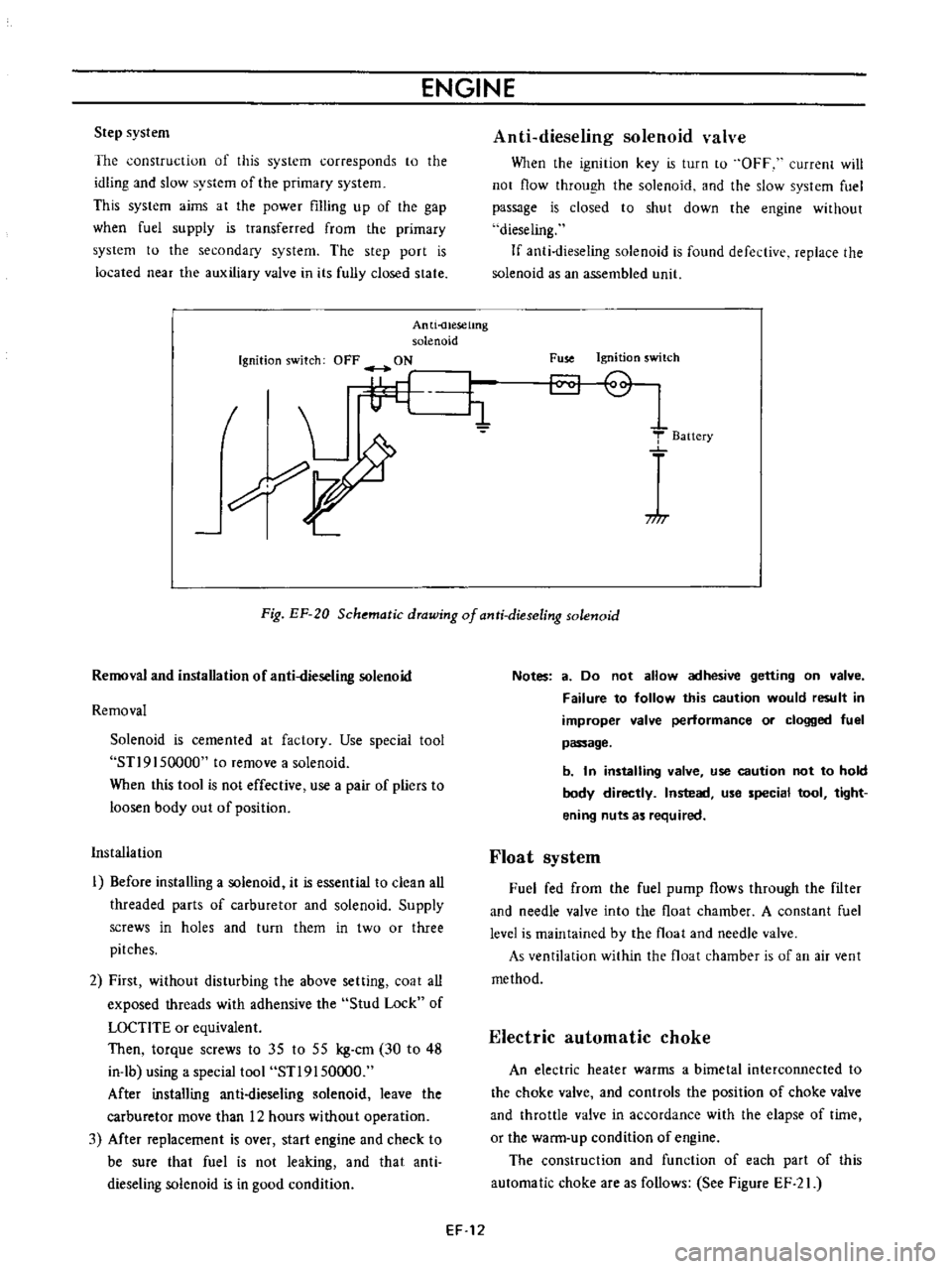
Anti
uesetmg
solenoid
Ignition
switch
OFF
ON
I
L
i1
7
I
Anti
dieseling
solenoid
valve
When
the
ignition
key
is
turn
to
OFF
current
will
not
flow
through
the
solenoid
and
the
slow
system
fuel
passage
is
closed
to
shut
down
the
engine
without
dieseling
If
anti
dieseling
solenoid
is
found
defective
replace
the
solenoid
as
an
assembled
llnit
Fuse
Ignition
switch
T
Baitery
717
Fig
EF
20
Schematic
drawing
of
anti
dieseling
solenoid
Removal
and
installation
of
anti
dieseling
solenoid
Removal
Solenoid
is
cemented
at
factory
Use
special
tool
STl9
I
50000
to
remove
a
solenoid
When
this
tool
is
not
effective
use
a
pair
of
pliers
to
loosen
body
out
of
position
Installation
I
Before
installing
a
solenoid
it
is
essential
to
clean
all
threaded
parts
of
carburetor
and
solenoid
Supply
screws
in
holes
and
turn
them
in
two
or
three
pitches
2
First
without
disturbing
the
above
setting
coat
all
exposed
threads
with
adhensive
the
Stud
Lock
of
LOCTlTE
or
equivalent
Then
torque
screws
to
35
to
55
kg
cm
30
to
48
in
lb
using
a
special
tool
STl9150000
After
installing
anti
dieseling
solenoid
leave
the
carburetor
move
than
12
hours
without
operation
3
Mter
replacement
is
over
start
engine
and
check
to
be
sure
that
fuel
is
not
leaking
and
that
anti
dieseling
solenoid
is
in
good
condition
Notes
a
Do
not
allow
adhesive
getting
on
valve
Failure
to
follow
this
caution
would
result
in
improper
valve
performance
or
clogged
fuel
passage
b
In
installing
valve
use
caution
not
to
hold
body
directly
Instead
use
special
tool
tight
ening
nuts
as
required
Float
system
Fuel
fed
from
the
fuel
pump
flows
through
the
filter
and
needle
valve
into
the
float
chamber
A
constant
fuel
level
is
maintained
by
the
float
and
needle
valve
As
ventilation
within
the
float
chamber
is
of
an
air
vent
method
Electric
automatic
choke
An
electric
heater
warms
a
bimetal
interconnected
to
the
choke
valve
and
controls
the
position
of
choke
valve
and
throttle
valve
in
accordance
with
the
elapse
of
time
or
the
warm
up
condition
of
engine
The
construction
and
function
of
each
part
of
this
automatic
choke
are
as
follows
See
Figure
EF
21
EF
12
Page 410 of 513
FUEl
SYSTEM
MA
JOR
SERVICE
OPERATIONS
A
completely
adjusted
and
serviced
carburetor
will
provide
the
engine
with
proper
mixture
at
all
speeds
Periodical
overhauling
which
cleans
all
components
and
passages
will
recover
the
originally
designed
performance
producing
the
engine
with
proper
gasoline
and
air
ratio
at
all
speeds
Passages
and
holes
of
the
carburetor
must
be
cleaned
carefully
Use
only
carburetor
solvent
and
com
pressed
air
to
clean
aU
passages
and
discharge
holes
Never
use
wire
or
other
pointed
tool
otherwise
accurately
calibrated
carburetor
will
be
affected
Removal
Remove
the
air
cleaner
2
Disconnect
the
fuel
line
vacuum
line
automatic
choke
harness
and
anti
dieseling
solenoid
harness
from
carburetor
3
Remove
the
throttle
lever
4
Remove
four
nuts
and
washers
retaining
the
carbuTe
tor
to
the
manifold
if
necessary
5
Lift
the
carburetor
and
remove
from
the
manifold
6
Remove
and
discard
the
gasket
used
between
the
carburetor
and
manifold
Disassembly
The
main
jets
and
needle
valves
on
both
primary
and
secondary
sides
are
accessible
from
outside
of
the
carbure
tor
for
disassembly
2
Remove
throttle
return
spring
3
Remove
pump
lever
shaft
take
out
pump
lever
and
pump
connecting
rod
4
Remove
rubber
pipe
from
choke
piston
5
Loosen
off
bolts
securing
servo
diaphragm
in
posi
tion
take
out
diaphragm
6
Back
off
total
of
five
bolts
which
hold
choke
in
position
and
remove
rods
of
starter
system
take
out
choke
chamber
In
removing
chamber
exercise
care
to
avoid
damaging
float
EF
19
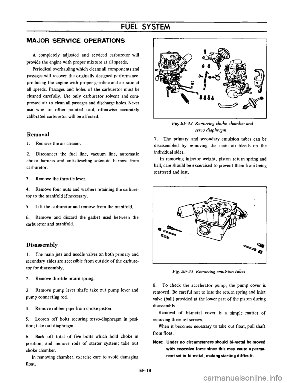
ilia
Fig
EF
32
Removing
choke
dwmherand
seroo
diaphragm
7
The
primary
and
secondary
emulsion
tubes
can
be
disassembled
by
removing
the
main
air
bleeds
on
the
individual
sides
In
removing
injector
weight
piston
return
spring
and
ball
care
should
be
excercised
to
prevent
them
from
being
scattered
and
lost
OQ
fI
Fig
EF
33
Removing
emulsion
tubes
8
To
check
the
accelerator
pump
the
pump
cover
is
removed
Be
careful
not
to
lose
the
return
spring
and
inlet
valve
ball
provided
at
the
lower
part
of
the
piston
during
disassemb
ly
Removal
of
bi
metal
cover
is
a
simple
matter
of
removing
three
set
screws
When
it
becomes
necessary
to
take
out
float
pull
shaft
from
float
Note
Under
no
circumstances
should
bi
metal
be
moved
with
excessive
force
since
this
may
cause
a
perma
nent
set
in
bi
metal
making
starting
difficult
Page 412 of 513
FUEL
SYSTEM
5
Check
venturi
clusters
for
loose
or
worn
parts
If
damage
or
looseness
exists
replace
cluster
assembly
6
Check
the
linkage
for
operating
condition
7
Inspect
the
operation
of
accelerating
pump
Pour
gasoline
into
the
float
chamber
and
operate
the
throttle
lever
Check
condition
of
gasoline
injection
from
the
accelerating
nozzle
Assembly
and
instalIetion
Assemble
and
install
the
carburetor
in
reverse
sequence
of
disassembly
and
removal
Replace
the
gaskets
if
necessary
When
disassembling
and
reassembling
the
interlock
link
and
related
components
be
careful
not
to
bend
or
deform
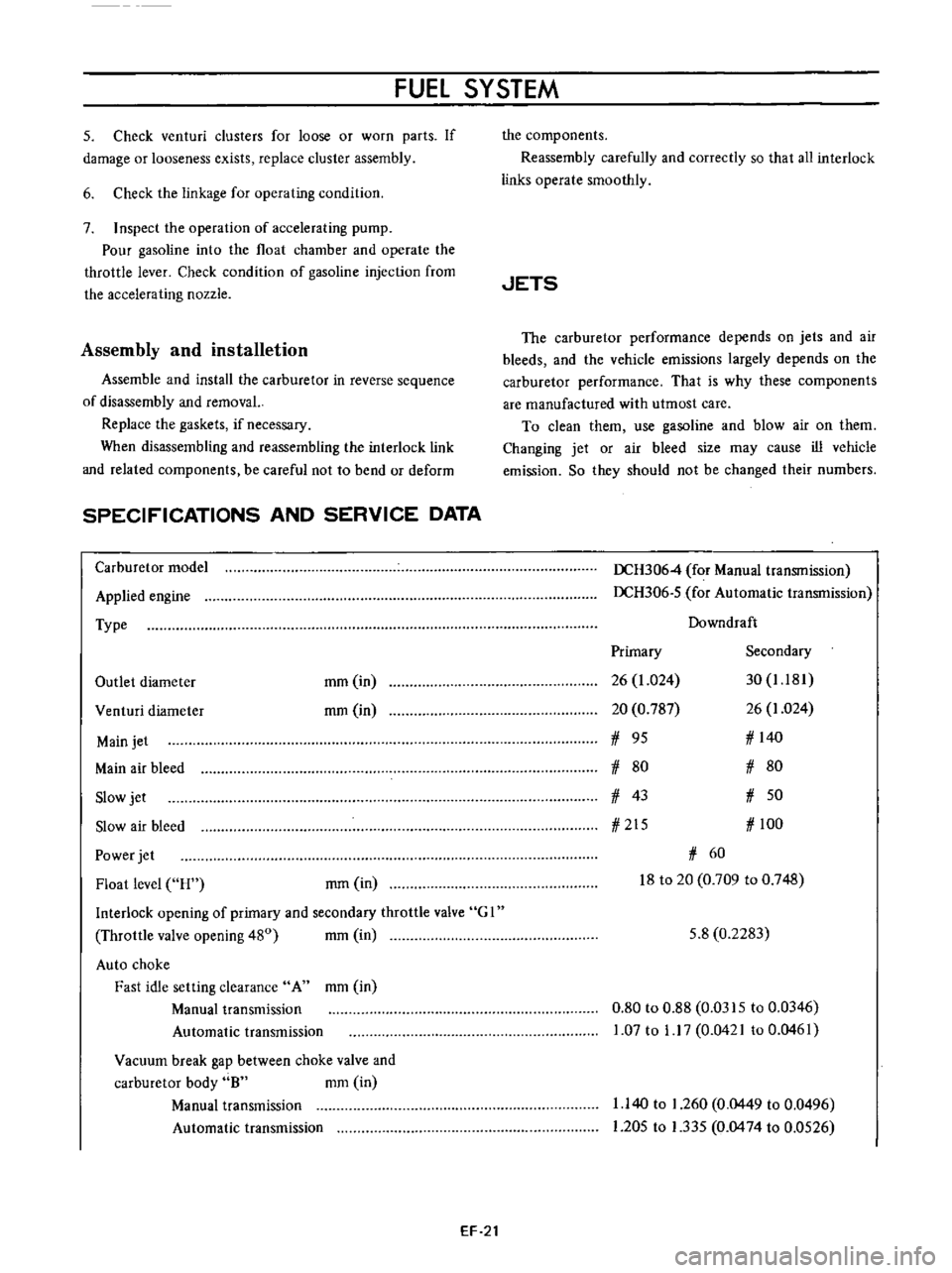
SPECIFICATIONS
AND
SERVICE
DATA
Carburetor
model
Applied
engine
Type
Outlet
diameter
mm
in
rom
in
Venturi
diameter
Main
jet
Main
air
bleed
Slow
jet
Slow
air
bleed
Power
jet
Float
level
H
rom
in
Interlock
opening
of
primary
and
secondary
throttle
valve
G
I
Throttle
valve
opening
480
mm
in
Auto
choke
Fast
idle
setting
clearance
A
mm
in
Manual
transmission
Automatic
transmission
Vacuum
break
gap
between
choke
valve
and
carburetor
body
8
mm
in
Manual
transmission
Automatic
transmission
EF
21
the
components
Reassembly
carefully
and
correctly
so
that
all
interlock
links
operate
smoothly
JETS
The
carburetor
performance
depends
on
jets
and
air
bleeds
and
the
vehicle
emissions
largely
depends
on
the
carburetor
performance
That
is
why
these
components
are
manufactured
with
utmost
care
To
clean
them
use
gasoline
and
blow
air
on
them
Changing
jet
or
air
bleed
size
may
cause
ill
vehicle
emission
So
they
should
not
be
changed
their
numbers
DCH3064
for
Manual
transmission
DCH306
5
for
Automatic
transmission
Downdraft
Primary
Secondary
26
1
024
30
1
181
20
0
787
26
1
024
1
95
1
140
1
80
1
80
1
43
1
50
1
215
1
100
1
60
18
to
20
0
709
to
0
748
5
8
0
2283
0
80
to
0
88
0
0315
to
0
0346
1
07
to
1
17
0
0421
to
0
0461
1
140
to
1
260
0
0449
to
0
0496
1
205
to
1
335
0
0474
to
0
0526