Page 321 of 513

ENGINE
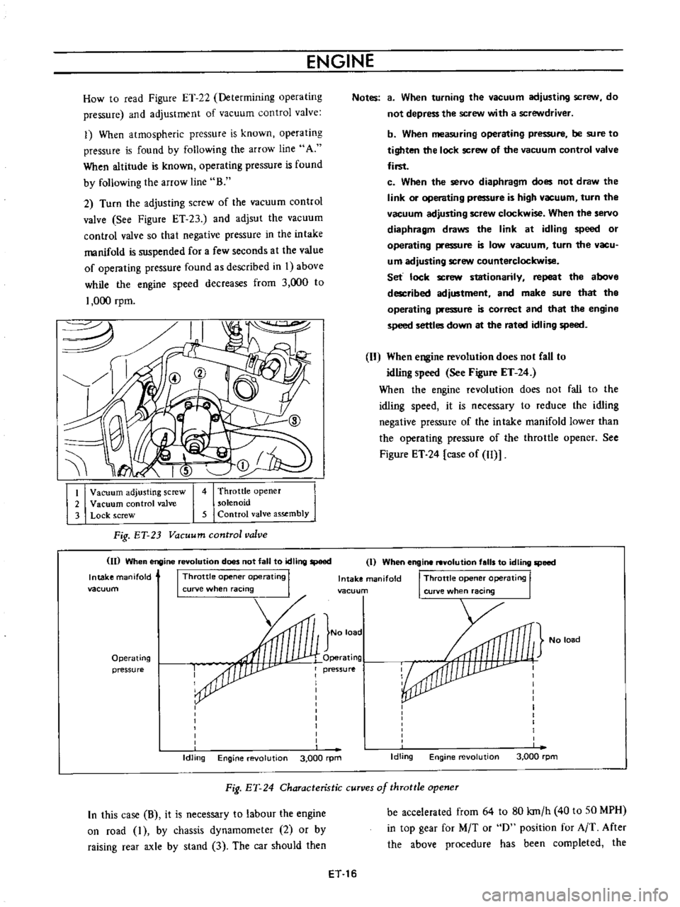
How
to
read
Figure
ET
22
Determining
operating
pressure
and
adjustment
of
vacuum
control
valve
1
When
atmospheric
pressure
is
known
operating
pressure
is
found
by
following
the
arrow
line
A
When
altitude
is
known
operating
pressure
is
found
by
following
the
arroW
line
B
2
Turn
the
adjusting
screw
of
the
vacuum
control
valve
See
Figure
ET
23
and
adjsut
the
vacuum
control
valve
so
that
negative
pressure
in
the
intake
manifold
is
suspended
for
a
few
seconds
at
the
value
of
operating
pressure
found
as
described
in
I
above
while
the
engine
speed
decreases
from
3
000
to
1
000
rpm
I
Vacuum
adjusting
screw
2
Vacuum
control
valve
3
Lock
screw
4
Throttle
opener
solenoid
5
Control
valve
assembly
Fig
ET
23
Vacuum
control
valve
II
When
engine
revolution
does
not
fall
to
tdling
speed
Intake
manifold
I
Throttle
opene
operating
I
vacuum
curve
when
racing
Operating
pressure
Idling
Engine
evolution
3
000
rpm
Notes
a
When
turning
the
vacuum
adjusting
scre
N
do
not
depress
the
screw
with
a
screwdriver
b
When
measuring
operating
pressure
be
sure
to
tighten
the
lock
screw
of
the
vacuum
control
valve
first
c
When
the
servo
diaphragm
does
not
draw
the
link
or
operating
pressure
is
high
vacuum
turn
the
vacuum
adjusting
screw
clockwise
When
the
servo
diaphragm
draws
the
link
at
idling
speed
or
operating
pressure
is
low
vacuum
turn
the
vacu
um
adjusting
screw
counterclockwise
Set
lock
screw
stationarily
repeat
the
above
described
adjustment
and
make
sure
that
tho
operating
pressure
is
correct
and
that
the
engine
speed
settles
down
at
the
rated
idling
speed
When
engine
revolution
does
not
CaU
to
idling
speed
See
Figure
ET
24
When
the
engine
revolution
does
not
fall
to
the
idling
speed
it
is
necessary
to
reduce
the
idling
negative
pressure
of
the
intake
manifold
lower
than
the
operating
pressure
of
the
throttle
opener
See
Figure
ET
24
case
of
Il
Il
I
When
engine
revolution
falls
to
idling
speed
Intake
manifold
I
Throttle
opene
operating
I
vacuun
curve
when
racing
No
load
No
load
Operating
pressure
I
I
I
I
I
I
I
I
I
Idling
Engine
revolution
3
000
rpm
Fig
EY
24
Characteristic
curves
of
throttle
opener
In
this
case
B
it
is
necessary
to
labour
the
engine
on
road
I
by
chassis
dynamometer
2
or
by
raising
rear
axle
by
stand
3
The
car
should
then
be
accelerated
from
64
to
80
kro
h
40
to
SO
MPH
in
top
gear
for
M
T
or
0
position
for
A
T
After
the
above
procedure
has
been
completed
the
ET
16
Page 322 of 513

EMISSION
CONTROL
AND
TUNE
UP
accelerator
pedal
is
released
During
the
testing
measure
the
throttle
opener
operating
pressure
to
see
whether
it
is
in
the
predetermined
value
or
not
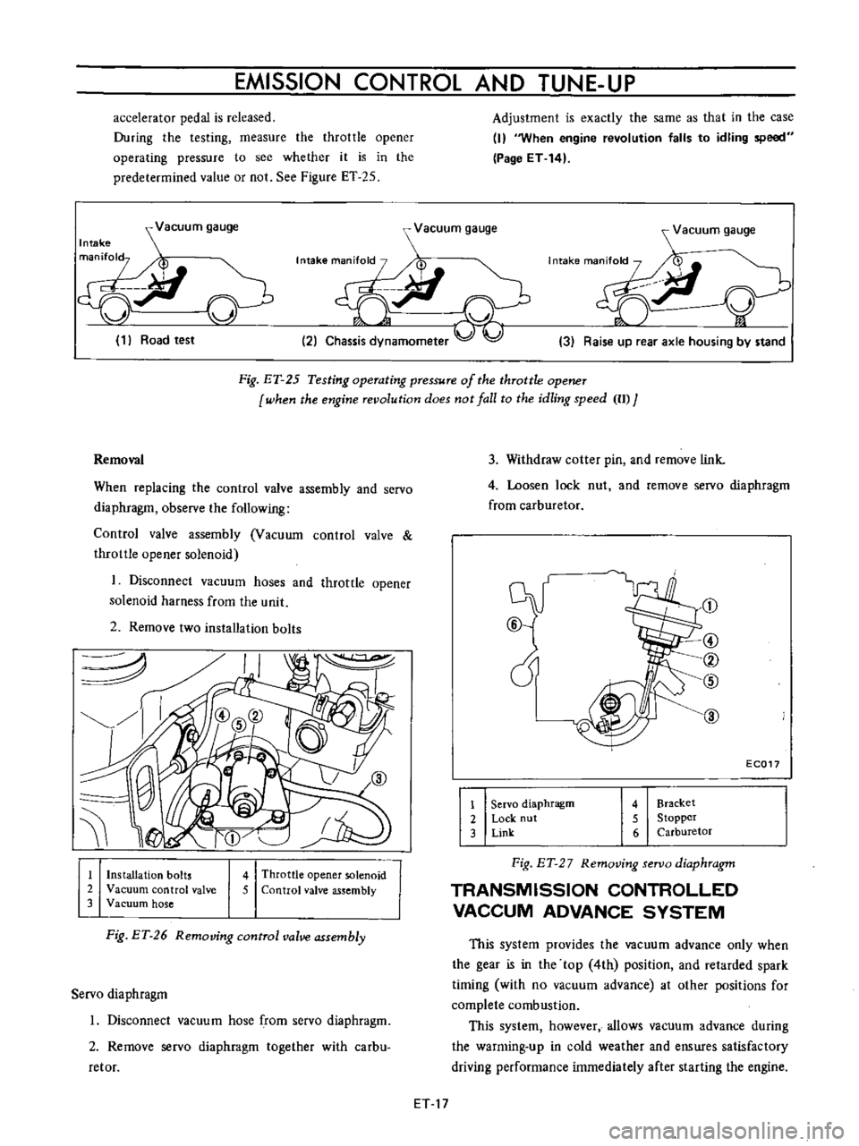
See
Figure
ET
25
Adjustment
is
exactly
the
same
as
that
in
the
case
I
When
engine
revolution
falls
to
idling
speed
Page
ET
14
Vacuum
gauge
Intake
man
fol
p
ci
J
v
1
Road
test
r
Vacuum
gauge
7I
t
i
2
Chassis
dynamometer
Vacuum
gauge
y
3
Raise
up
rear
axle
housing
by
stand
Fig
ET
25
Testing
operating
pressure
of
the
throttle
opener
when
fhe
engine
revolufion
does
not
lall
fo
fhe
idling
speed
II
J
3
Withdraw
cotter
pin
and
remove
link
4
Loosen
lock
nut
and
remove
servo
diaphragm
from
carburetor
Removal
When
replacing
the
control
valve
assembly
and
servo
diaphragm
observe
the
following
Control
valve
assembly
Vacuum
control
valve
throttle
opener
solenoid
1
Disconnect
vacuum
hoses
and
throttle
opener
solenoid
harness
from
the
unit
2
Remove
two
installation
bolts
J
@
cY
@
1
Servo
diaphragm
2
Lock
nut
3
Link
@
CV
@
EC017
4
Bracket
5
Stopper
6
Carburetor
1
Installation
bolts
2
Vacuum
control
valve
3
Vacuum
hose
4
Throttle
opener
solenoid
5
Control
valve
assembly
Fig
ET
2
7
Removing
servo
diaphragm
TRANSMISSION
CONTROLLED
VACCUM
ADVANCE
SYSTEM
Fig
ET
26
Removing
control
valve
assembly
This
system
provides
the
vacuum
advance
only
when
the
gear
is
in
the
top
4th
position
and
retarded
spark
timing
with
no
vacuum
advance
at
other
positions
for
complete
combustion
This
system
however
allows
vacuum
advance
during
the
warming
up
in
cold
weather
and
enswes
satisfactory
driving
performance
immediately
after
starting
the
engine
Servo
diaphragm
1
Disconnect
vacuum
hose
from
servo
diaphragm
2
Remove
servo
diaphragm
together
with
carbu
retor
ET
17
Page 323 of 513

ENGINE
Gear
Vacuum
advance
Note
R
No
1st
No
2nd
No
3rd
No
4th
Yes
Immediately
after
starting
the
engine
in
cold
weather
vacuum
advance
is
available
for
all
gear
positions
A12
Engine
with
Manual
Transmission
Distributor
Ignition
switch
8
1
J
Battery
Thermo
switch
9
Transmission
L
r
l
r
Vacuum
advance
unit
To
carburetor
Needle
valve
OFF
l
To
air
cleaner
ON
Vacuum
cutting
valve
solenoid
Top
switch
Top
off
I
7
1
OFF
Vacuum
actuated
ON
Vacuum
eminated
into
atmosphere
Fig
ET
28
Schematic
drawing
of
transmission
controlled
vacuum
advance
system
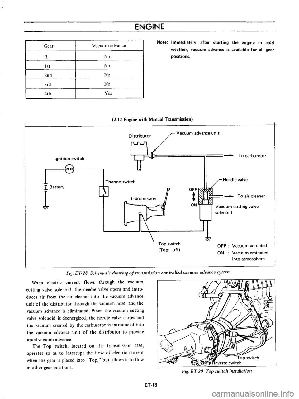
When
electric
current
flows
through
the
vacuum
cutting
valve
solenoid
the
needle
valve
opens
and
intro
duces
air
from
the
air
cleaner
into
the
vacuum
advance
unit
of
the
distributor
through
the
vacuum
hose
and
the
vacuum
advance
is
eliminated
When
the
vacuum
cutting
valve
solenoid
is
deenergized
the
needle
valve
closes
and
the
vacuum
created
by
the
carburetor
is
introduced
into
the
vacuum
advance
unit
of
the
distributor
to
provide
usual
vacuum
advance
The
Top
switch
located
on
the
transmission
case
operates
so
as
to
interrupt
the
flow
of
electric
current
when
the
gear
is
placed
into
Top
but
allows
it
to
flow
in
other
gear
positions
Fig
ET
29
Top
switch
installation
ET
18
Page 324 of 513

EMISSION
CONTROL
AND
TUNE
UP
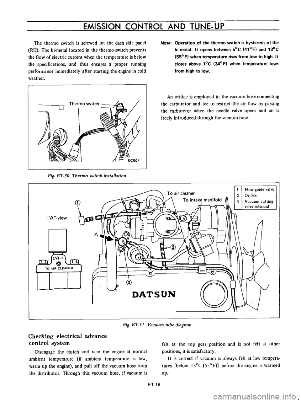
The
thermo
switch
is
screwed
on
the
dash
side
panel
RH
The
bi
metallocated
in
the
thermo
switch
prevents
the
flow
of
electric
current
when
the
temperature
is
below
the
specifications
and
thus
ensures
a
proper
running
performance
immediately
after
starting
the
engine
in
cold
weather
A
Fig
ET
30
Thermo
switch
installation
A
view
I
llf
F
ID
1
Note
Operation
of
the
thermo
switch
is
hysteresis
of
the
bi
metal
It
opens
between
50C
410FI
and
130C
550
F
when
temperature
rises
from
low
to
high
It
closes
above
lOC
34
0
F
when
temperature
lows
from
high
to
low
An
orifice
is
employed
in
the
vacuum
hose
connecting
the
carburetor
and
tee
to
restrict
the
air
flow
by
passing
the
carburetor
when
the
needle
valve
opens
and
air
is
freely
introduced
through
the
vacuum
hose
1
Flow
guide
valve
2
Orifice
3
Vacuum
cutting
valve
solenoid
r
d
01
DATSUN
Fig
ET
31
Vacuum
tube
diagram
Checking
electrical
advance
control
system
Disengage
the
clutch
and
race
the
engine
at
normal
ambient
temperature
if
ambient
temperature
is
low
warm
up
the
engine
and
pull
off
the
vacuum
hose
from
the
distributor
Through
this
vacuum
hose
if
vacuum
is
felt
at
the
top
gear
position
and
is
not
felt
at
other
positions
it
is
satisfactory
It
is
correct
if
vacuum
is
always
felt
at
low
tempera
tures
below
l30C
550F
before
the
engine
is
warmed
up
ET
19
Page 325 of 513

ENGINE
Caution
lock
the
front
and
rear
wheels
by
fully
pulling
the
parking
brake
lever
before
con
ducting
this
test
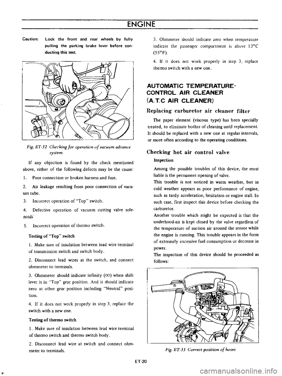
Fig
ET
32
Checking
for
operation
of
vacuum
advance
system
If
any
objection
is
found
by
the
check
mentioned
above
either
of
the
following
defects
may
be
the
cause
Poor
connection
or
broken
harness
and
fuse
2
Air
leakage
resulting
from
poor
connection
of
vacu
um
tube
3
Incorrect
operation
of
Top
switch
4
Defective
operation
of
vacuum
cutting
valve
sole
naid
5
Incorrect
operation
of
thermo
switch
Testing
of
Top
switch
1
Make
sure
of
insulation
between
lead
wire
terminal
of
transmission
switch
and
switch
body
2
Disconnect
lead
wires
at
the
switch
and
connect
ohmmeter
to
tenninals
3
Ohmmeter
should
indicate
infmity
co
when
shift
lever
is
in
Top
gear
position
And
it
should
indicate
zero
at
other
gear
position
including
Neutral
posi
tion
4
If
it
does
not
work
properly
in
step
3
replace
the
switch
with
a
new
one
Testing
of
thermo
switch
I
MaJ
e
sure
of
insulation
between
lead
wire
terminal
of
thermo
switch
and
thetmo
switch
body
2
Disconnect
lead
wire
at
switch
and
connect
ohm
meter
to
terminals
Ohmmeter
should
indicate
zero
when
temperature
indicate
the
passenger
compartment
is
above
l30C
550F
4
If
it
does
not
work
properly
in
step
3
replace
thermo
switch
with
a
new
one
AUTOMATIC
TEMPERATURE
CONTROL
AIR
CLEANER
A
T
C
AIR
CLEANER
Replacing
carburetor
air
cleaner
filter
The
paper
element
viscous
type
has
been
specially
treated
to
eliminate
bother
of
cleaning
until
replacement
It
should
be
replaced
with
a
new
one
at
regular
intervals
or
more
often
according
to
the
operating
conditions
Checking
hot
air
control
valve
Inspection
Among
the
possible
troubles
of
this
device
the
most
liable
is
the
permanent
opening
of
valve
This
trouble
is
not
noticed
in
warm
weather
but
in
cold
weather
appears
as
poor
performance
of
engine
such
as
tardy
acceleration
hesitation
or
engine
stall
In
such
case
first
inspect
this
device
before
checking
the
carburetor
Another
trouble
which
might
be
expected
is
that
the
underhood
air
is
kept
closed
by
the
valve
regardless
of
the
temperature
of
suction
air
around
the
sensor
while
the
engine
is
running
This
ttOuble
appears
in
the
form
of
extremely
excessive
fuel
consumption
or
decrease
in
power
The
inspection
of
this
device
should
be
proceeded
as
follows
Fig
ET
33
Correct
position
of
hoses
ET
20
Page 326 of 513

EMISSION
CONTROL
AND
TUNE
UP
Appearance
1
First
inspect
whether
vacuum
hoses
are
connected
to
correct
positions
2
Inspect
hoses
for
cracks
distortion
or
plugging
Checking
of
vacuum
motor
I
With
engine
shut
down
inspect
the
position
of
valve
placing
a
mirror
at
the
end
of
inlet
pipe
for
inspec
tion
The
correct
condition
of
valve
is
that
it
keeps
the
inlet
of
underhood
air
open
and
that
of
hot
air
closed
Otherwise
inspect
the
linkage
of
valve
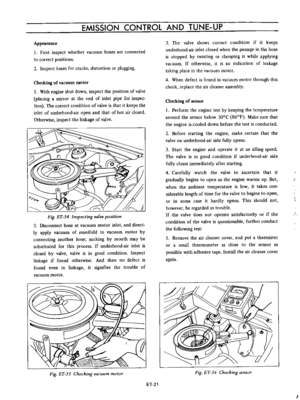
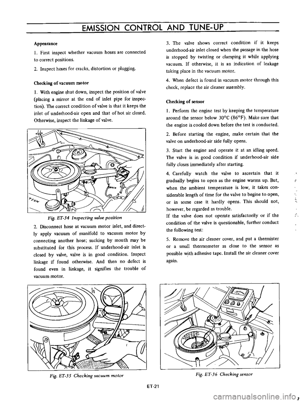
Fig
ET
34
Inspecting
valve
position
2
Disconnect
hose
at
vacuum
motor
inlet
and
direct
ly
apply
vacuum
of
manifold
to
vacuum
motor
by
connecting
another
hose
sucking
by
mouth
may
be
substituted
for
this
process
If
underhood
air
inlet
is
closed
by
valve
valve
is
in
good
condition
Inspect
linkage
if
found
otherwise
And
then
no
defect
is
found
even
in
linkage
it
signifies
the
trouble
of
vacuum
motor
Fig
ET
35
Checking
vacuum
motor
ET
21
3
The
valve
shows
correct
condition
if
it
keeps
underhood
air
inlet
closed
when
the
passage
in
the
hose
is
stopped
by
twisting
or
clamping
it
while
applying
vacuum
If
otherwise
it
is
an
indication
of
leakage
taking
place
in
the
vacuum
motor
4
When
defect
is
found
in
vacuum
motor
through
this
check
replace
the
air
cleaner
assembly
Checking
of
sensor
I
Perform
the
engine
test
by
keeping
the
temperature
around
the
sensor
below
300C
860F
Make
sure
that
the
engine
is
cooled
down
before
the
test
is
conducted
2
Before
starting
the
engine
make
certain
that
the
valve
on
underhood
air
side
fully
opens
3
Start
the
engine
and
operate
it
at
an
idling
speed
The
valve
is
in
good
condition
if
underhood
air
side
fully
closes
immediately
after
starting
4
Carefully
watch
the
valve
to
ascertain
that
it
gradually
begins
to
open
as
the
engine
warms
up
But
when
the
ambient
temperature
is
low
it
takes
con
siderable
length
of
time
for
the
valve
to
begine
to
open
or
in
some
case
it
hardly
opens
This
should
not
however
be
regarded
as
trouble
If
the
valve
does
not
operate
satisfactorily
or
if
the
condition
of
the
valve
is
questionable
further
conduct
the
following
test
5
Remove
the
air
cleaner
cover
and
put
a
thermister
or
a
small
thermometer
as
close
to
the
sensor
as
possible
with
adhesive
tape
Install
the
air
cleaner
cover
again
Fig
ET
36
Checking
sensor
1
Page 327 of 513

ENGINE
6
Start
the
engine
and
continue
idling
as
described
under
paragraphs
I
2
and
3
above
When
several
minutes
have
passed
and
the
valve
is
partially
opened
read
the
thermister
indication
It
is
correct
if
the
reading
falls
between
380C
1000
F
and
550C
1300
F
If
the
reading
is
abnormal
replace
the
sensor
7
On
the
engine
equipped
with
an
idle
compensator
as
service
option
do
as
follows
before
replacing
the
sensor
Clog
hose
on
idle
compensator
side
by
twisting
or
clamping
it
and
check
the
temperature
as
given
in
paragraphs
5
and
6
above
If
the
thermometer
shO
vs
correct
temperature
replace
the
idle
compensa
tOf
if
the
reading
is
abnormal
replace
the
sensor
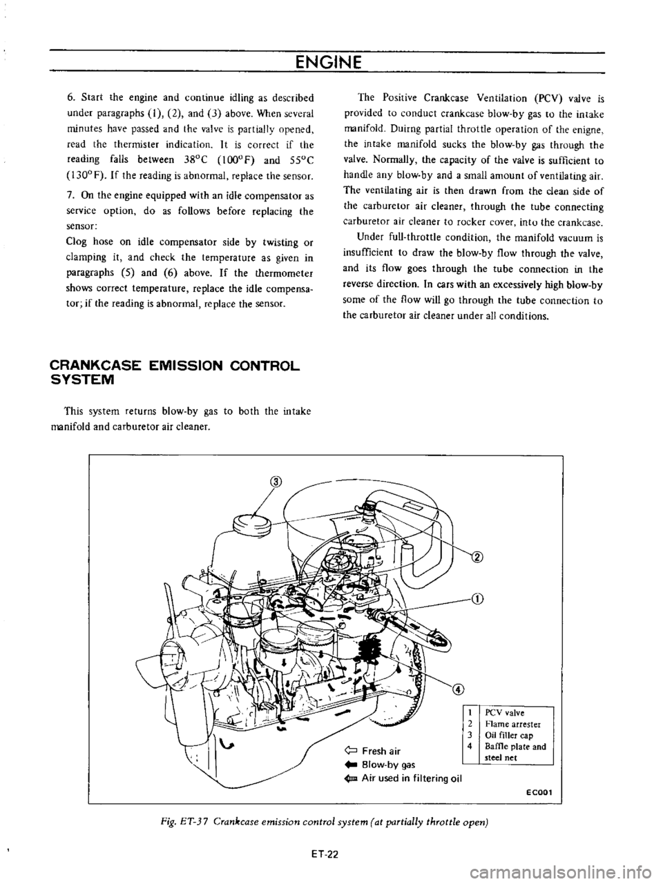
CRANKCASE
EMISSION
CONTROL
SYSTEM
This
system
returns
blow
by
gas
to
both
the
intake
manifold
and
carburetor
air
cleaner
The
Posirive
Crankcase
Ventilation
PCV
valve
is
provided
to
conduct
crankcase
blow
by
gas
to
the
intake
manifold
Duirng
partial
throttle
operation
of
the
enigne
the
intake
manifold
sucks
the
blow
by
gas
through
the
valve
Normally
the
capacity
of
the
valve
is
sufficient
to
handle
any
blow
by
and
a
small
amount
of
ventilating
air
The
ventilating
air
is
then
drawn
from
the
clean
side
of
the
carburetor
air
cleaner
through
the
tube
connecting
carburetor
air
cleaner
to
rocker
cover
intu
the
crankcase
Under
full
throttle
condition
the
manifold
vacuum
is
insufficient
to
draw
the
blow
by
flow
through
the
valve
and
its
flow
goes
through
the
tube
connection
in
the
reverse
direction
In
cars
with
an
excessively
high
blow
by
some
of
the
flow
will
go
through
the
tube
connection
to
the
carburetor
air
cleaner
under
all
conditions
j
Fresh
air
Blow
by
gas
1m
Air
used
in
filtering
oil
t
2
3
4
PCV
valve
Flame
arrester
Oil
filler
cap
Baffle
plate
and
steel
net
ECOOl
Fig
ET
3
7
Crankcase
emission
control
system
at
partially
throttle
open
ET
22
Page 328 of 513

EMISSION
CONTROL
AND
TUNE
UP
CD
@
Fresh
air
Blow
by
gas
Air
used
in
filtering
oil
1
PCV
valve
2
Flame
arrester
3
Oil
filler
cap
4
Baffle
plate
and
steel
net
E
C002
Fig
ET
J8
Crankcase
emission
control
system
at
full
throttle
open
Checking
and
replacing
PCV
valve
Test
PCV
valve
in
accordance
with
the
following
me
thod
With
engine
running
at
idle
remove
the
ventilator
hose
from
PCV
valve
If
the
valve
is
working
a
hissing
noise
will
be
heard
as
air
passes
through
the
valve
and
a
strong
vacuum
should
be
felt
immediately
when
a
finger
is
placed
over
the
valve
inlet
If
the
valve
is
plugged
replace
with
a
new
one
Check
for
deposit
plugging
in
the
hose
Clean
if
necessary
Intake
manifold
l
illlr
nnnl
UUUU
l
I
G
EC014
FigET
39
Cross
sectional
view
of
PCV
valve
Checking
ventilation
hoses
I
Check
hoses
and
hose
connections
for
leaks
2
Disconnect
all
hoses
and
blow
them
out
with
compressed
air
If
any
hose
can
not
be
free
of
obstructions
replace
with
a
new
one
Insure
that
the
flame
arrester
is
surely
inserted
in
the
hose
between
the
air
cleaner
and
rocker
cover
EVAPORATIVE
EMISSION
CONTROL
SYSTEM
Checking
engine
compartment
hose
connections
and
fuel
vapor
control
valves
Checking
fuel
tank
vapor
liquid
separator
and
vapor
vent
line
I
Check
all
hoses
and
fuel
tank
ftIler
cap
2
Disconnect
the
vapor
vent
line
connecting
flow
guide
valve
to
vapor
liquid
separator
ET
23